
Related Manuals for Riello RTC Series


Summary of Contents for Riello RTC Series
- Page 1 RTC 3000-4000-5000-6000 RTC 8000-10000 ISTRUZIONI PER IL RESPONSABILE DELL'IMPIANTO, PER L'INSTALLATORE E PER IL SERVIZIO TECNICO DI ASSISTENZA...
- Page 2 Sua competenza e RTC 5000 20107179 capacità tecnica. RTC 6000 20107180 RTC 8000 20112393 Buon lavoro e rinnovati ringraziamenti. RTC 10000 20112394 Riello S.p.A. CONFORMITÀ Commercial Boilers AHRI Standard BTS-2000 ITALIANO...
-
Page 3: Table Of Contents
INDICE 1 GENERALE . . . . . . . . . . . . . . . . . . . . . . . . . . . . . . . . . . . . . . . . . . 4 3 MESSA IN SERVIZIO . -
Page 4: Generale
GENERALE GENERALE Il non utilizzo della caldaia per un lungo periodo comporta l’effettuazione delle operazioni descritte nel paragrafo spe- cifico. 1.1 Avvertenze generali Questo libretto è parte integrante dell’apparecchio e di con- seguenza deve essere conservato con cura e dovrà SEMPRE ac- Al ricevimento del prodotto assicurarsi dell’integrità... - Page 5 GENERALE NOTICE! DANGER: Risk of personal injury or death from electric shock! − The installation must comply with all applicable national, − Before removing the front panel, disconnect the heating state, and local codes, rules, and regulations. system from the electrical power supply by shutting off the −...
-
Page 6: Descrizione Dell'apparecchio
GENERALE 1.3 Descrizione dell’apparecchio 1.4 Identificazione Le caldaie in acciaio RTC sono generatori a condensazione da cen- L’apparecchio è identificabile attraverso: trale termica, a tre giri di fumo, per il riscaldamento e per la pro- duzione di acqua sanitaria se abbinate ad un bollitore. Le parti della caldaia che sono a contatto con i prodotti della com- bustione, sono realizzate interamente in Acciaio Inox stabilizzato al titanio, in grado di assicurare la miglior resistenza dall'azione... -
Page 7: Struttura
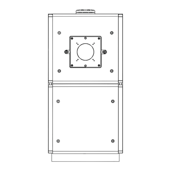
GENERALE 1.5 Struttura RTC 3000-RTC 4000-RTC 5000-RTC 6000 Bruciatore Visore fiamma con presa di pressione Portello Pannellatura Mandata impianto Attacco valvola di sicurezza Ritorno impianto (AT) Camera di combustione Ritorno impianto (BT) 10 Cassa fumi Raccordo canale da fumo 12 Portina di ispezione 13 Scarico condensa 14 Scarico caldaia... - Page 8 GENERALE RTC 8000-RTC 10000 Bruciatore Visore fiamma con presa di pressione Portello Pannellatura Mandata impianto Attacco valvola di sicurezza Ritorno impianto (AT) Camera di combustione Ritorno impianto (BT) 10 Cassa fumi Raccordo canale da fumo 12 Portina di ispezione 13 Scarico condensa 14 Scarico caldaia 15 Support plane - Max load 330 lb (150kg)
-
Page 9: Dati Tecnici
GENERALE 1.6 Dati tecnici 1.6.1 Ratings Descrizione RTC 3000 RTC 4000 RTC 5000 RTC 6000 RTC 8000 RTC 10000 Min Input 1000 Max Input 3000 4000 5000 6000 8000 10000 Condition 1 2550 3400 4250 5100 6800 8500 Output Condition 2 2940 3920 4900... -
Page 10: Destinazione D'uso
GENERALE 1.7 Destinazione d'uso Limiti di sicurezza Safety limits Value This boiler must only be used for the purpose specified by the ma- Maximum allowable temperature: 210°F (99°C) nufacturer and for which it is designed. Maximum Allowable Working Pressure The RTC can be operated with gas, oil, and combination burners. 160 psi (11 bar) (MAWP) For a list of the approved burners, see specific paragraph in this... -
Page 11: Combustibili Idonei
GENERALE 1.11 Bruciatori b) EXEMPTIONS: The following equipment is exempt from 248 CRM 5.08(2)(a) 1 through 4: − The equipment listed in Section 10 entitled “Equipment Not Follow the burner manufacturer’s instructions when fitting the Required To Be Vented” in the most current edition of NFPA burner. -
Page 12: Burner Plate Accessories Kit
GENERALE BRUCIATORI BOILERS BRUCIATORI BOILERS MODELLO MODELLO 3000 4000 5000 6000 8000 10000 3000 4000 5000 6000 8000 10000 x ● RS120/E RS130/E x ● x ● RS160/E RS190/E RS68/EV RS280/E 20126364 x ● RS120/EV RS300/E 20126364 x ● x ● RS160/EV RS310/E MISTI GASOLIO/GAS... -
Page 13: Upper Door Accessories Kit
GENERALE 1.11.3 Upper door accessories kit In the following table are shown the codes for the upper door kit that shall be ordered as accessory for some matching boiler-bur- ner. BRUCIATORI BOILERS MODELLO 3000 4000 5000 6000 8000 10000 RX1500 20136220 20136221 RX1800 20136220 20136221... -
Page 14: Installazione
79.1" 82.9" 86.8" 92.3" 76.8" 81.7" inch La busta documenti va conservata in un luogo sicuro. L’even- Peso netto 5,578 6,702 7,485 9,087 12,747 16,149 tuale duplicato è da richiedere a Riello S.p.A. che si riserva di addebitarne il costo. -
Page 15: Movimentazione E Rimozione Dell'imballo
INSTALLAZIONE 2.3 Movimentazione e rimozione dell'imballo È vietato disperdere nell’ambiente e lasciare alla portata dei bambini il materiale dell’imballo in quanto può essere poten- ziale fonte di pericolo. Deve quindi essere smaltito secondo Prima di effettuare le operazioni di rimozione dell'imballo e quanto stabilito dalla legislazione vigente. -
Page 16: Locale Di Installazione
INSTALLAZIONE 2.4 Locale di installazione 2.4.1 Zone di rispetto minime consigliate La caldaia RTC va installata in locali ad uso esclusivo rispondenti Le zone di rispetto per il montaggio e la manutenzione della cal- alle Norme Tecniche ed alla Legislazione vigente e dotati di aper- daia sono riportate in figura. -
Page 17: Collegamenti Idraulici
INSTALLAZIONE 2.5 Collegamenti idraulici Le dimensioni e il posizionamento degli attacchi idraulici della caldaia RTC è riportato nella tabella seguente. Prima dell'installazione si consiglia di effettuare un lavaggio accurato di tutte le tubazioni dell'impianto per rimuovere gli eventuali residui di lavorazione. RTC 3000-RTC 4000-RTC 5000-RTC 6000 4”... -
Page 18: Posizionamento Pozzetti Sonde
INSTALLAZIONE 2.6 Posizionamento pozzetti sonde RTC 3000-RTC 4000-RTC 5000-RTC 6000 a) 3/4"NPT b) 1/2" NPT Boiler RTC 3000 RTC 4000 RTC 5000 RTC 6000 Thermowell lenght min. max. min. max. min. max. min. max. 2.5" 3.75" 2.5" 6" 2.5" 6" 2.5"... - Page 19 INSTALLAZIONE RTC 8000-RTC 10000 a) 3/4"NPT b) 1/2" NPT Boiler RTC 8000 RTC 10000 Thermowell lenght min. max. min. max. 2.5" 7.5" 2.5" 7.5" 1 - Outlet operating temperature sensor (1/2" NPT) 63mm 190mm 63mm 190mm 2.5" 9.5" 2.5" 9.5" 2 - Over- temperature protection (1/2"...
-
Page 20: Perdite Di Carico Lato Acqua
INSTALLAZIONE 2.6.1 Perdite di carico lato acqua ∆T=20°F ∆T=30°F ∆T=40°F ∆T=60°F Perdita di Perdita di Perdita di Perdita di Modello Portata Portata Portata Portata carico carico carico carico (GPM) (psi) (GPM) (psi) (GPM) (psi) (GPM) (psi) RTC 3000 1.56 0.86 0.58 0.34 RTC 4000... -
Page 21: Flow Limits
INSTALLAZIONE 2.6.2 Flow limits RTC boilers does not require a minimum flow rate in order to maintain warranty. The boiler has been designed to operate with a tem- perature difference between the supply and return of up to 100 °F . Flow should be initiated with the start of the burner to minimize temperature fluctuations and control deviations. -
Page 22: Reconditioning Old Heating Systems
INSTALLAZIONE 2.6.7 Elimination air and gas from central heating NOTICE: system − Loss of water from the system, and the consequential need to add water, can be caused not only by leaks from the circuit, but also from the incorrect sizing of the expansion When designing new heating systems, it is necessary to eliminate vessel or precharge pressure. -
Page 23: Impianti Idraulici Di Principio
INSTALLAZIONE 2.7 Impianti idraulici di principio La scelta e l'installazione dei componenti dell'impianto è de- mandata per competenza all'Installatore, che dovrà operare The following P&ID represent the typical arrangement for the most secondo le regole della buona tecnica e della Legislazione vi- common types of installation and they are only a suggestion for gente. - Page 24 INSTALLAZIONE Single Boiler Combination Heating & Domestic Water Plant RITORNO IMPIANTO BT (*) MANDATA IMPIANTO REINTEGRO ACQUA 3 12 10 3 RITORNO ENTRATA IMPIANTO AT (*) UTENZE SANITARIE RIT AT RIT BT INGRESSO ACQUA Caldaia Valvola di ritegno Bruciatore Degasatore Valvole di sezionamento Bollitore Circolatore impianto...
- Page 25 INSTALLAZIONE Multiple Boiler Piping Schematic with Sequencing Panel RITORNO RITORNO REINTEGRO IMPIANTO IMPIANTO ACQUA BT (*) AT (*) MANDATA IMPIANTO RIT AT RIT BT INGRESSO ACQUA RIT AT RIT BT RIT AT RIT BT Caldaia Scarico condensa Bruciatore Scarico Valvole di sezionamento Valvola di intercettazione Circolatore impianto Valvola di ritegno...
- Page 26 INSTALLAZIONE Multiple Boiler Piping with Primary and Secondary Piping REINTEGRO ACQUA MANDATA IMPIANTO RIT BT RITORNO IMPIANTO BT (*) INGRESSO RIT BT ACQUA RIT BT Caldaia Sifone Bruciatore Scarico condensa Valvole di sezionamento Scarico Circolatore impianto Valvola di intercettazione Valvole non ritorno Valvola di ritegno Valvola di sfiato automatico Serbatoio di miscelazione...
- Page 27 INSTALLAZIONE Multiple-Boiler Piping with Motorized Sequencing Valves RITORNO MANDATA IMPIANTO IMPIANTO RIT BT INGRESSO ACQUA RIT BT RIT BT Caldaia Sifone Bruciatore Scarico condensa Valvole di sezionamento Scarico Circolatore impianto Valvola di intercettazione Valvole non ritorno Valvola di sequenziamento motorizzata Valvola di sfiato automatico Valvola di sicurezza caldaia Manometro...
- Page 28 INSTALLAZIONE Two-Boiler Combination Heating & Domestic Water Plant RITORNO RITORNO MANDATA IMPIANTO IMPIANTO IMPIANTO AT (*) BT (*) REINTEGRO 16 17 ACQUA 4 5 3 3 12 10 3 ENTRATA RIT AT RIT BT INGRESSO ACQUA UTENZE 16 17 16 SANITARIE RIT AT RIT BT...
- Page 29 INSTALLAZIONE Multi-Boiler Combination RITORNO MANDATA IMPIANTO IMPIANTO BT (*) REINTEGRO ACQUA 16 17 RIT BT INGRESSO ACQUA 17 16 RIT BT 17 16 RIT BT Caldaia Sifone Bruciatore Scarico condensa Valvole di sezionamento Scarico Circolatore impianto Valvola di intercettazione Valvole non ritorno Valvola di regolazione Valvola di sfiato automatico Degasatore...
-
Page 30: Evacuazione Della Condensa
INSTALLAZIONE 2.8 Evacuazione della condensa 2.9 Neutralizzazione della condensa Le caldaia a condensazione RTC producono un flusso di conden- È raccomandato installare sempre un kit di neutralizzazione della sati dipendente dalle condizioni di esercizio. condensa. Nella tabella seguente è riportata la portata di con- Il massimo flusso orario di condensa prodotta è... -
Page 31: Scarico Dei Prodotti Della Combustione
INSTALLAZIONE 2.10 Scarico dei prodotti della combustione RTC 8000-RTC 10000 Il condotto di scarico (1) ed il raccordo alla canna fumaria (2) de- vono essere realizzati in conformità alle Norme, alla Legislazione vigente ed ai regolamenti locali, utilizzando tubi rigidi impermea- bili ai fumi, idonei a resistere nel tempo alle sollecitazioni mecca- niche, al calore, all'azione dei prodotti della combustione e delle loro condense. -
Page 32: Venting Requirements
INSTALLAZIONE 2.10.1 Venting Requirements Vertical Terminations: − Roof penetrations should follow all appliance codes and the vent manufacturer‘s instructions. The vent should never be installed at less than the required clearances to WARNING: Risk of system damage or personal injury! combustible materials per UL, NFPA and local codes. -
Page 33: Combustion Air From An Adjacent Room
INSTALLAZIONE 2.10.4 Combustion Air from an adjacent room Where combustion air is to be used from within the building, air must be provided into the equipment room through two perma- nent openings into the inferior building. Each opening must have a minimum free area of 1 square inch for each 1,000 Btu/hr of the total input rating of all fuel burning equipment in the space. -
Page 34: Cerniere Portello
INSTALLAZIONE 2.11 Cerniere portello 2.11.1 Variazione del senso di apertura portelli Per rispondere alle diverse esigenze costruttive, sono stati impie- Le caldaie sono predisposte in fabbrica con il portello che si apre gati due diversi sistemi di incernieratura dei portelli: da sinistra verso destra. - Page 35 INSTALLAZIONE Portello - RTC 8000 - RTC 10000 Rimuovere i quattro dadi (7) ed estrarre la staffa (8). Aprire il portello, svitare i dadi (1) di fissaggio della staffa (2) di copertura e rimuoverla. Operando in maniera inversa a quanto descritto montare la cer- Successivamente richiudere ermeticamente il portello fissando niera nel lato opposto.
-
Page 36: Collegamento Per La Messa A Terra
INSTALLAZIONE 2.12 Collegamento per la messa a terra RTC 8000-RTC 10000 Per la messa a terra del corpo caldaia è previsto sulla testata po- steriore (Mod. RTC 3000-RTC 6000), e nella parte centrale della struttura (Mod. RTC 8000-RTC 10000) un punto di connessione da collegare ad un efficace impianto di terra. -
Page 37: Installazione Della Pannellatura
INSTALLAZIONE 2.13 Installazione della pannellatura − Agganciare il pannello superiore anteriore (8) nei perni predisposti. RTC 3000-RTC 4000-RTC 5000-RTC 6000 Per il montaggio della pannellatura, procedere come riportato in seguito: − Aprire le asole pretranciate poste sul pannello laterale (2) o (3) (a seconda del lato su cui si desidera installare il quadro di comando), in corrispondenza dei passacavi “ovali”... - Page 38 INSTALLAZIONE − Montare i pannelli superiori (13, 14, 15, 16) RTC 8000-RTC 10000 Per il montaggio della pannellatura, procedere come riportato in seguito: − Aprire le asole pretranciate poste sul pannello laterale (3) o (4) (a seconda del lato su cui si desidera installare il quadro di comando), in corrispondenza dei passacavi “ovali”...
- Page 39 INSTALLAZIONE − Agganciare i pannelli laterali (1, 2, 3, 4, 5, 6, 7, 8) ai longhe- − Agganciare il pannello posteriore superiore (13) nei perni roni superiori della caldaia. predisposti. − Fissare n°8 perni AVP sui fori della parte anteriore dei pan- nelli 9, 10, 11, 12;...
-
Page 40: Accessorio Supporto Quadro Elettrico
INSTALLAZIONE 2.14 Accessorio supporto quadro elettrico − Montare i pannelli posteriori centrali (15, 16) inserendoli la- teralmente e agganciandoli sui perni dei pannelli superiore e inferiore. (*) Control panel support kit: accessory not supplied as standard. − Montare il profilo anteriore 17 agganciandolo sui perni dei pannelli superiori. -
Page 41: Messa In Servizio
MESSA IN SERVIZIO 3 MESSA IN SERVIZIO 3.4 Making the electrical connection 3.1 Preparazione alla prima messa in servizio DANGER: Danger to life through electric shock! − Before opening the boiler, isolate the heating system across all life phases and secure against unintentional recon- NOTICE: Risk of boiler damage through contaminated combu- nection. -
Page 42: Flushing The Heating System
MESSA IN SERVIZIO 3.6 Flushing the heating system 3.8 Preparing the heating system for operation If the heating system contains several heating circuits, these must Observe the following points during commissioning: be flushed one after the other. − Before commissioning, vent the heating system via the To prevent contamination in the boiler, flush the heating system ventilation facilities provided for this purpose. -
Page 43: Commissioning Report
MESSA IN SERVIZIO 3.10 Commissioning report The boiler can be operated with a gas or dual fuel burner. − Carefully complete the commissioning report for the relevant approved burner. − Sign all completed commissioning work and enter the date. COMMISSIONING STEPS COMMENTS (SIGNATURE) Flush the heating system. -
Page 44: Spegnimento
SPEGNIMENTO 4 SPEGNIMENTO CAUTION: Risk of system damage through frost. When there is a frost, the heating system can freeze up if it is not operational, e.g. because of a fault shutdown. − When there is a risk of frost, protect your heating system against freezing up. -
Page 45: Ispezione E Manutenzione
SPEGNIMENTO 5 ISPEZIONE E MANUTENZIONE 5.4 Regolazione portello Per evitare pericolose fuoriuscite dei gas di combustione, è necessario 5.1 Why is regular maintenance important? che il portello sia costantemente e uniformemente appoggiato sulle doppie guarnizioni. Per la regolazione seguire quanto indicato: Heating systems require regular maintenance and service for the RTC 3000-RTC 4000-RTC 5000-RTC 6000 following reasons:... -
Page 46: Cleaning The Boiler
SPEGNIMENTO 5.5 Cleaning the boiler 5.6 Pulizia esterna La pulizia della pannellatura esterna della caldaia deve essere ef- fettuata con panni inumiditi con acqua e sapone. DANGER: Risk to life from electric shock! Nel caso di macchie tenaci inumidire il panno con una miscela al −... -
Page 47: Ispezione Della Caldaia Lato Acqua
SPEGNIMENTO 5.8 Ispezione della caldaia lato acqua Modelli RTC 8000 - RTC 10000 Effettuare l'ispezione è importante per verificare lo stato di con- servazione delle superfici di scambio termico e la presenza di fan- ghi o calcare. É possibile ispezionare l'interno della caldaia attraverso le appo- site aperture L'ispezione deve essere eseguita con caldaia non in funzione, arrestata in sicurezza e fredda (temperatura ambiente) e con... -
Page 48: Inspection And Maintenance Reports
SPEGNIMENTO 5.8.1 Inspection and maintenance reports The inspection and maintenance reports provide an overview of the required inspection and service steps that should be carried out annually. Warranty: − Annual inspection and service are part of the warranty terms. Complete these reports after inspections and service. The report can also be used as copying template: −... -
Page 49: Eventuali Anomalie E Rimedi
SPEGNIMENTO 5.9 Eventuali anomalie e rimedi PROBLEM CAUSE TROUBLESHOOTING TROUBLESHOOTING Heat exchanger dirty. − Clean the flue gas pipes. Heat exchanger and burner mismatched. − Check specifications and settings. The boiler does not reach its set tempe- Insufficient gas flow burner. −... -
Page 50: Environmental Protection/Disposal
ENVIRONMENTAL PROTECTION/DISPOSAL 6 ENVIRONMENTAL PROTECTION/DISPOSAL Environmental protection is one of the fundamental company po- licies of the Riello. We regard quality of performance, economy and environmental protection as equal objectives. Environmental protection laws and regulations are strictly adhe- red to. - Page 52 RIELLO S.p.A. Via Ing. Pilade Riello, 7 37045 - Legnago (VR) www.riello.it RIELLO NORTH AMERICA 35 Pound Park Road Hingham, Massachusetts U.S.A. 02043 2165 Meadowpine Blvd Mississauga, Ontario Canada L5N 6H6 www.rielloboilers.com Poiché l’Azienda è costantemente impegnata nel continuo perfezionamento di tutta la sua produzione, le caratteristiche estetiche e dimen-...
Need help?
Do you have a question about the RTC Series and is the answer not in the manual?
Questions and answers