Advertisement
Quick Links
Stratomaster Maxi Single
Flight II
Primary flight instrument
The Flight II is a ultra compact, complete primary flight system intended as main flight instrument
on smaller aircraft or as backup / secondary flight instrument.
This 3.5" instrument provides many functions from Altimeter, Airspeed to Fuel level/flow, Engine
RPM and many secondary functions, including an automatic flight log.
The Flight II 's light weight, small size and high level of functionality in addition to excellent value
for money make it an ideal choice for many applications.
The Flight II makes and ideal companion to the Stratomaster E1 universal engine monitor for a
compact, low cost yet highly functional and complete cockpit solution.
Advertisement

Related Manuals for MGL Avionics Stratomaster Maxi Single Flight II


Summary of Contents for MGL Avionics Stratomaster Maxi Single Flight II
- Page 1 Stratomaster Maxi Single Flight II Primary flight instrument The Flight II is a ultra compact, complete primary flight system intended as main flight instrument on smaller aircraft or as backup / secondary flight instrument. This 3.5” instrument provides many functions from Altimeter, Airspeed to Fuel level/flow, Engine RPM and many secondary functions, including an automatic flight log.
- Page 2 The Flight II functions The Flight II provides the following functions: Altimeter (-700ft to >40.000ft range) Airspeed indicator (16-250 mph range) Analog VSI (+/-1600 ft/min range) Digital VSI (+/-10.000 ft/min range) Automatic flight duration timer Real time clock for local time and flight log use Fuel flow (with optional Fuel flow sender) Fuel level calculated from fuel flow Fuel level obtained from optional fuel level sender...
-
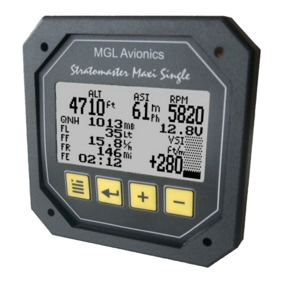
Page 3: Operating The Keys
The main screen of the Flight II During operation of the Flight II instrument, the following display is shown: Active flight indicator Airspeed Altimeter indicator Engine RPM display Local pressure setting (QNH) System voltage Analog VSI Auxiliary flight information display Digital VSI (four display pages) Operating the keys... - Page 4 The Flight II is intended for use as primary flight instrument in smaller aircraft with limited panel space or as secondary or backup instrument in larger aircraft. The Flight II can be combined with the MGL Avionics E1 Engine monitoring system for a very compact, full instrumentation solution at very low cost yet extremely versatile functionality.
- Page 5 Setting up the Flight II Press the Menu key to enter the menu. You can move forward and backwards in the menu by using the + and – keys. To change or select a menu item, move the highlight to the desired item and then press the Select (Enter) key.
-
Page 6: Setup Units
We recommend that you choose automatic flight logging. Fuel level … If the instrument is operating with an external fuel level sender, then this entry will show the current fuel level, you cannot edit the entry. If you have selected to operate with a fuel flow sender only, then you can use this function to set your current fuel level. - Page 7 Set time/date This function allows you to set the time and date of the internal real time clock. Please note that the internal real time clock maintains a year calendar for every leap year interval only. This means that every leap year you need to reset the year to the current year. Set Hobbs This function allows you to set the engine Hobbs meter to any value.
- Page 8 QNH ... Select if you want your local pressure readout in millibars (mB) or inches or mercury (“HgA). ASI ... Select your preferred units. You can select statute miles per hour (mph), kilometers per hour (km/h) or nautical miles per hour (knots). According to this selection your airspeed will be indicated in mph, km/h or knots.
- Page 9 Flight: Manual / Auto Select if you would like the instrument to detect the start and end of flights automatically or if you would like to do this manually. We recommend you select automatic flight detect. With automatic flight detection, flights will start logging when: a) Engine RPM is above the Take-off limit (set in the “Setup Limits”...
- Page 10 The Setup Limits menu Items in the “Setup limits menu” RPM Hobbs … Enter the RPM value above which you would like the engine Hobbs meter to count engine time. You may choose that engine idle is not counted towards the Hobbs reading, if so, set the RPM limit just higher than your normal engine idle RPM value.
-
Page 11: The Calibration Menu
The value you enter is in units of measure as you have selected in the “Setup Units menu”. The alarm is by means of flashing the fuel level reading as well as activating the external alarm output. Should your instrument not be showing the page containing the fuel level when this alarm first activates, the relevant page will be shown automatically. - Page 12 The K-Factor is the number of pulses generated by the fuel flow sender for one liter of fuel. The dual range fuel flow sender supplied by MGL Avionics has a K-Factor of 7000 in the low flow mode (jet installed) and 1330 for the high flow mode (no jet installed).
- Page 13 Fill your tank to an approximate known level (perhaps marked using a felt pen). Set the FF-3 to calculate fuel level from fuel flow (disable the fuel level sender using the menu function “LevelSend”). Set the fuel level to read 40 liters – the exact value is not important. Now fly of a quantity of fuel, perhaps 25 liters as example (very roughly –...
- Page 14 Performing the calibration procedure. Note: You start with an empty tank, you need a measuring jug or fueling device that has calibration marks and you need enough fuel to fully fill the tank. Regardless of your use of a fuel flow sender, you can install a fuel level sender into your fuel tank.
- Page 15 The calibration positions may be edited by using the + and – keys. This allows you, in theory, to copy calibration settings from one instrument to another. We however recommend that you do go though the calibration procedure even if the two aircraft are identical in all respects. Tolerances do exist and the calibration cancels these out.
- Page 16 RPM Calib Enter the number of pulses per RPM. For engines with an uneven number of cylinders like three cylinder four stroke engines you can enter values containing fractions (usually 1.5 in this example). Most four stroke engines would generate one pulse for every two revolutions per cylinder. A four cylinder automotive four stroke engine would thus generate 2 pulses per revolution.
- Page 17 Setting up the Flight II for the first time. After you have completed the physical installation of the Flight II, you need to setup the following items before you can proceed with flight testing: a) Select your mode of operation: We recommend to select automatic flight detection.
-
Page 18: Technical Specifications
We recommend that measures are taken to prevent voltage transients in excess of this limit. MGL Avionics recommends the fitment of a fuse in line with a 33V transorb (available from MGL Avionics at low cost) to protect electronic instruments, radios and intercom systems. Only one such arrangement is required for a cluster of instruments. - Page 19 failure or malfunction. Under no circumstances does the manufacturer condone usage of this instrument for IFR flights.
- Page 20 Installing the Flight II Fuel flow sender Negative supply (airframe ground) Braid from Ignition flow sender 2K2 resistor coil Blue wire from flow 20Volt Breaker sender zener diode Green Fuel level sender Ground Red wire from flow senders Reference ground Terminal strip (not supplied) to engine block To other instruments...
- Page 21 Installing the Flight II is quite straight forward. Connect the supply terminals to your aircrafts power supply (you need a dropping resistor or pre- regulator for 24/28V systems). Install suitable power supply protection if you have a supply that can contain large voltage transients such as can be created by starter motors and solenoids.
- Page 22 Please note that this kind of tubing is not advised for pressurized aircraft. In this case you would need to obtain aircraft grade tubing of suitable diameter. You would also have to use hose clamps to fasten the hose onto the Stratomaster pitot and static ports. The Flight II allows you to calibrate the airspeed reading.
- Page 23 Various pickup / sensor installation possibilities Note: On Rotax DCDI ignition systems it Grey rev counter wire may be required to install a ballast +5VDC resistor as shown. A typical value is 220 GROUND Ballast ohms. Many resistor installations can omit this.
Need help?
Do you have a question about the Stratomaster Maxi Single Flight II and is the answer not in the manual?
Questions and answers