Table of Contents
Advertisement
INSTRUCTION HANDBOOK
Electric Pallet Truck
PTE15-C&SPTE15-C
WARNING
Do not use the pallet truck before reading and
understanding these operating instructions.
NOTE:
Please check the designation of your
present type at the last page of this
document as well as on the ID-plate.
Keep for future reference.
Scan it,
For more information
Service Hotline: 4008-836115
Version 10/2020
PTE15-C/SPTE15-C-SMS-001-CHN
Advertisement
Table of Contents

Related Manuals for Noblelift PTE15-C


Summary of Contents for Noblelift PTE15-C
- Page 1 Scan it, For more information Service Hotline: 4008-836115 INSTRUCTION HANDBOOK Electric Pallet Truck PTE15-C&SPTE15-C WARNING Do not use the pallet truck before reading and understanding these operating instructions. NOTE: Version 10/2020 Please check the designation of your PTE15-C/SPTE15-C-SMS-001-CHN present type at the last page of this document as well as on the ID-plate.
- Page 2 FOREWORD Before operating the truck, read this ORIGINAL INSTRUCTION HANDBOOK carefully and understand the usage of the truck completely. Improper operation could create danger. This handbook describes the usage of different electric pallet trucks. When operating and servicing the truck, make sure, that it applies to your type. Keep this handbook for future reference.
-
Page 3: Table Of Contents
TABLE OF CONTENTS CORRECT APPLICATION ........................ 3 DESCRIPTION OF THE PALLET TRUCK ..................4 Overview of the main components ....................4 Main technical data ........................5 Description of the safety devices and warning labels (Europe and other, excepting USA) ... 7 Identification plate ......................... -
Page 4: Correct Application
1. CORRECT APPLICATION It is only allowed to use this electric pallet truck according to this instruction handbook. The trucks described in this handbook are self propelled electric power pallet trucks. The trucks are designed to lift, lower and transport palletized loads. A wrong usage can cause human injuries or can damage equipment. -
Page 5: Description Of The Pallet Truck
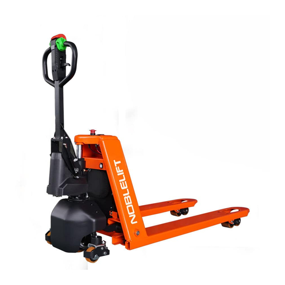
Overview of the main components Fig. 1: Overview main components Safety (belly) button Tiller Load roller Finger tip control 10. Electric assembly Display 11. Apron Emergency button 12. Driving unit Hydraulic unit cover 13. Side roller (option for PTE15-C/SPTE15-C) Chassis... -
Page 6: Main Technical Data
b. Main technical data Fig. 2: Technical data... - Page 7 Table 1: Main technical data for standard version Type sheet for industrial truck acc. to ( VDI2198 Manufacturer`stype designation PT E15-C SPT E15-C Battery Power(battery,diesel,petrolgas,manual) Pedestrian Operator type Load Capacity / rated load Q (t) c (mm) Load centre distance x (mm) Load distance, centre of drive axle to fork Wheelbase...
-
Page 8: Description Of The Safety Devices And Warning Labels (Europe And Other, Excepting Usa)
Description of the safety devices and warning labels (Europe and other, excepting USA) Fig. 3: Safety and warning labels Manual lowering label Sticker to read and follow this instruction Reminding Label(swtich) Sticker (NOBLELIFT) Capacity sticker(1500Kg) Crane hook label Identification plate (ID-plate) Filling sticker “No passengers” decal Warning Label The truck is equipped with an emergency button (5) which stops all lifting-, lowering-, driving- functions and engages the failsafe electromagnetic brake when it is pressed. -
Page 9: Identification Plate
d. Identification plate Pallet Truck Designation, type xxxx Rated capacity xxxx xxxx Rated voltage Self weight Battery weight maximum Battery weight minimum Own mass without battery without load Lifting height maximum xxxx Serial number XXXXXXXXXX Device code XXXXXXXXXX Manufacturer XXXXXXXXXXXXXXX Manufacturer XXXXXXXXXXXXXXX Fig. -
Page 10: Commissioning, Transporting, Decommissioning
(5) or press the button on display. 4. COMMISSIONING, TRANSPORTING, DECOMMISSIONING a. Commissioning Table 2: Commissioning data Type SPTE15-C/ PTE15-C Commissioning weight [kg] 130kg Dimensions [mm] 1530x540x1250 After receiving our new pallet truck or for re-commissioning you have to do following before (firstly) operating the truck: ... -
Page 11: Decommissioning
Fig. 5: Lifting with a crane Fig. 6:Fixing points Transportation DURING TRANSPORTATION ON A LORRY OR TRUCK ALWAYS FASTEN THE TRUCK SECURELY. Lower the forks and park the truck securely. Fasten the truck according to Fig. 6 by fixing dedicated lashing belts to each side of the trucks crane hook holes and fasten the other side at the transporting truck. -
Page 12: Operating Instructions
DO NOT PARK THE TRUCK ON INCLINED SURFACES The truck is equipped with an electromagnetic failsafe stopping and parking brake. Always lower the forks fully. Press the emergency button (5). b. Lifting DO NOT OVERLOAD THE TRUCK! PTE15-C/SPTE15-C THE MAXIMUM CAPACITY OF IS 1500 kg. -
Page 13: Lowering
Travel with the lowered forks fully underneath the pallet and move the finger tip control (3) to the lifting position. Press the tiller of SPTE15-C to lift the loads. Press the lifting button (Fig. 7, 16) until you reached the desired lifting height. c. -
Page 14: Steering
Drive carefully the truck to the destination. Watch the route conditions and adjust the travelling speed with the accelerator button. The truck has vertical driving function. Release button to cancel vertical driving With tiller in its vertical position, press turtle button (Fig.7, 17) and hold still, move the accelerator button to activate driving function and travel slowly, which is suitable for narrow space operation. -
Page 15: Battery Charging And Replacement
Table 3: Available batteries Model Battery specification PTE15-C/SPTE15-C 48V12Ah lithium battery, 5kg IT IS ONLY ALLOWED TO USE LITHIUM BATTERIES. PLEASE CONSIDER THE MAXIMUM OPERATING TEMPERATURE OF THE BATTERIES a. -
Page 16: Charging
Battery State of charge The battery's state of charge indicated through 4 LED indicate lamps. Each lamp represents 25% of the battery charge. As the battery becomes discharged, the lamps turn off progressively, one after another, in proportion to the value of the residual battery charge. When the battery is nearly running out, the LED lamp on the leftmost (L side) keeps flashing until it goes out and the battery runs out. -
Page 17: Regular Maintenance
Inspect the hydraulic oil level, refill if necessary Refill the hydraulic oil ( 12 month or 1500 working hours ) Check and adjust function of the pressure valve (1500kg (PTE15-C) +0/+10%) Mechanical system Inspect the forks for deformation and cracks ... -
Page 18: Lubricating Points
Inspect and lubricate the steering bearing if necessary Inspect and lubricate the pivot points if necessary Lubricate the grease nipples Electrical system Inspect the electric wiring for damage Check the electric connections and terminals Test the Emergency switch function ... -
Page 19: Check And Refill Hydraulic Oil
The oil level in the oil tank should be between min and max marks with fully lowered forks. If necessary add oil at the filling point. d. Checking electrical fuses Fig. 15 Location of fuses for PTE15-C/SPTE15-C Table 8: Size of the fuses Rate... -
Page 20: Trouble Shooting
TROUBLE SHOOTING If the truck has malfunctions follow the instructions, mentioned in chapter 6. Table 9: Trouble shooting TROUBLE CAUSE REPAIR Load weight too high Lift only the max. capacity, mentioned on the ID-plate Battery low power Charge the battery Load can’t be Lifting contactor failure Check and contact with service support for... -
Page 21: Wiring/ Circuit Diagram
10. WIRING/ CIRCUIT DIAGRAM a. Electrical circuit diagram PTE15-C Electrical lifting Fig.16: Electric diagram FU 1 :10A FU 01 : 30A... - Page 22 Table 10: Description of electrical diagram Code Item Code Item Battery Electricity meter DC power switch Accelerator FU01 30A fuse Horn 10A fuse Emergency reverse switch Controller Lifting switch Pump motor Turtle speed switch Traction motor Horn button Electromagnetic brake Charger Interlock switch Micro switch...
- Page 23 SPTE15-C Manual lifting FU1 :10A Fig.17: Electric diagram FU01 : 30A...
- Page 24 Table 11: Description of electrical diagram Code Item Code Item Battery Interlock switch DC power switch Electricity meter FU01 30A fuse Accelerator 10A fuse Horn Controller Emergency reverse switch Pump motor Turtle speed switch Traction motor Horn button Electromagnetic brake Charger...
-
Page 25: Hydraulic Circuit
b. Hydraulic circuit Lifting cylinder Lowering valve Pressure control valve Throttle valve Hydraulic power unit Oil tank Fig. 18: Hydraulic circuit...
Need help?
Do you have a question about the PTE15-C and is the answer not in the manual?
Questions and answers