Table of Contents
Advertisement
Quick Links
Advertisement
Chapters
Table of Contents

Related Manuals for IEI Technology PM-LX-800


Summary of Contents for IEI Technology PM-LX-800
- Page 1 PM-LX-800 CPU Card Page 1...
- Page 2 REVISION HISTORY Title PM-LX-800 Motherboard Revision Number Description Date of Issue Initial release November 2006 COPYRIGHT NOTICE The information in this document is subject to change without prior notice in order to improve reliability, design and function and does not represent a commitment on the part of the manufacturer.
-
Page 3: Table Of Contents
PM-LX-800 CPU Card Table of Contents INTRODUCTION....................13 1.1 PM-LX-800 M ............14 OTHERBOARD NTRODUCTION 1.1.1 PM-LX-800 Motherboard Applications ............14 1.1.2 PM-LX-800 Motherboard Benefits ..............14 1.1.3 PM-LX-800 Motherboard Features ..............14 1.2 PM-LX-800 M ..............15 OTHERBOARD VERVIEW 1.2.1 PM-LX-800 Motherboard Connectors............. - Page 4 4.1.1 Installation Notices ..................66 4.2 U ......................67 NPACKING 4.2.1 Unpacking Precautions..................67 4.2.2 Checklist......................68 4.3 PM-LX-800 CPU B ..............68 OARD NSTALLATION 4.3.1 DIMM Module Installation ................69 4.3.1.1 Purchasing the Memory Module............... 69 4.3.1.2 SO-DIMM Module Installation ..............69 4.3.2 Compact Flash Disk Installation ..............
- Page 5 4.3.11 LPT Port Installation ..................74 4.3.12 Power Connection..................74 4.3.13 TTL LCD Installation..................74 4.3.14 USB Port Installation..................74 4.3.15 VGA Port Installation ..................75 4.3.16 Mounting the PM-LX-800 Motherboard............75 4.3.17 Airflow Consideration..................75 4.4 J ..................76 UMPER ONFIGURATION 4.5 C...
- Page 6 BIOS CONFIGURATION OPTIONS ..............133 A.1 BIOS C ................134 ONFIGURATION PTIONS WATCHDOG TIMER ..................137 ADDRESS MAPPING..................141 C.1 I/O A ....................142 DDRESS C.2 1 MB M ................142 EMORY DDRESS C.3 IRQ M .................... 143 APPING ABLE C.4 DMA C ................
- Page 7 PM-LX-800 CPU Card List of Figures Figure 1-1: PM-LX-800 Motherboard Overview (Front Side) ........15 Figure 1-2: PM-LX-800 Motherboard Overview (Solder Side) .........15 Figure 2-1: Data Flow Block Diagram................23 Figure 2-2: PXE: Pre-Boot Execution Environment..........28 Figure 3-1: Connector and Jumper Locations (Front Side) ........32 Figure 3-2: Connector and Jumper Locations (Solder Side)........33...
- Page 8 Figure 6-2: AMD LX/GX CD Driver Menu..............120 Figure 6-3: Access Windows Control Panel............121 Figure 6-4: Double Click the System Icon ............. 122 Figure 6-5: Double Click the Device Manager Tab..........122 Figure 6-6: Device Manager List ................123 Figure 6-7: Expand the Display Adapters Category ..........
- Page 9 PM-LX-800 CPU Card List of Tables Table 1-1: Technical Specifications ................17 Table 2-1: Geode LX Graphics Processor Features ..........24 Table 2-2: Power Consumption .................28 Table 3-1: Peripheral Interface Connectors..............34 Table 3-2: Onboard Jumper ..................34 Table 3-3: 12V / 5V Power Connector Pinouts ............35 Table 3-4: 12V Input Connector Pinouts ..............36...
- Page 10 List of BIOS Menus BIOS Menu 1: AwardBIOS CMOS Setup Utility ............80 BIOS Menu 2: Standard CMOS Features ..............82 BIOS Menu 3: IDE Primary Master................85 BIOS Menu 4: Advanced BIOS Features..............88 BIOS Menu 5: Advanced Chipset Features ..............95 BIOS Menu 6: Flat Panel Configuration ..............98 BIOS Menu 7: Integrated Peripherals..............
- Page 11 PM-LX-800 CPU Card Glossary AC ’97 Audio Codec 97 Hard Disk Drive ACPI Advanced Configuration and Integrated Data Electronics Power Interface Input/Output Advanced Power Management ICH4 I/O Controller Hub 4 ARMD ATAPI Removable Media Device L1 Cache Level 1 Cache...
- Page 12 THIS PAGE IS INTENTIONALLY LEFT BLANK Page 12 IEI ® Technology, Corp.
-
Page 13: Introduction
PM-LX-800 CPU Card Chapter Introduction Page 13... -
Page 14: Pm-Lx-800 Motherboard Introduction
The PM-LX-800 is particularly suitable for low power and fan-less applications. The PM-LX-800 supports a full range of functions for an AT compatible industrial computer in a space-saving 90mm x 96mm profile. The PM-LX-800 is equipped with an on-board low-power consumption and high performance AMD™... -
Page 15: Pm-Lx-800 Motherboard Overview
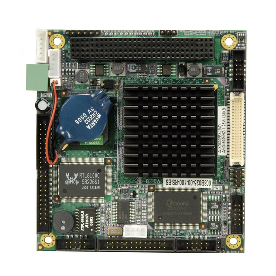
PM-LX-800 CPU Card 1.2 PM-LX-800 Motherboard Overview Figure 1-1: PM-LX-800 Motherboard Overview (Front Side) Figure 1-2: PM-LX-800 Motherboard Overview (Solder Side) Page 15... -
Page 16: Pm-Lx-800 Motherboard Connectors
The location of these connectors on the motherboard can be seen in Figure 1-1 and Figure 1-2. These connectors are fully described in Chapter 3. 1.2.2 Technical Specifications: PM-LX-800 motherboard technical specifications are listed in Table 1-1. Detailed descriptions of each specification can be found in Chapter 2. SPECIFICATION DESCRIPTION AMD™... -
Page 17: Table 1-1: Technical Specifications
PM-LX-800 CPU Card SPECIFICATION DESCRIPTION Display CRT integrated in AMD™ LX 800 24 bit TTL integrated in AMD LX 800 HDD Interface One IDE channel supports two Ultra ATA 100/66/33 devices Power Support AT power support Power Consumption +5V @ 1.13A (LX-800, 500MHz, DDR 333, 1GB RAM) - Page 18 THIS PAGE IS INTENTIONALLY LEFT BLANK Page 18 IEI ® Technology, Corp.
-
Page 19: Detailed Specifications
PM-LX-800 CPU Card Chapter Detailed Specifications Page 19... -
Page 20: Cpu Support
2.1 CPU Support The PM-LX-800 has a preinstalled AMD LX 800 processor. Technical specifications for the AMD LX 800 processor are listed below: x86/x87-compatible core Processor frequency up to 500 MHZ 64K I/64K D L1 cache and 128K L2 cache Split I/D cache/TLB (Translation Look-Aside Buffer) 64-bit DDR Memory interface. -
Page 21: System Chipset
PM-LX-800 CPU Card 2.2 System Chipset The PM-LX-800 motherboard has an AMD Geode™ CS5536 chipset installed. The AMD Geode™ CS5536 is a companion device for the AMD Geode™ LX 800 to create a high-performance, low-power x86 solution for embedded applications. - Page 22 LPC (Low Pin Count) Port General Purpose I/Os (GPIOs) 8 Multi-Function General Purpose Timers (MFGPTs) Real-Time Clock (RTC) with CMOS RAM Power Management Controller: ACPI v2.0 compliant Page 22 IEI ® Technology, Corp.
-
Page 23: Data Flow
PM-LX-800 CPU Card 2.2.1 Data Flow Figure 2-1 shows the data flow between the system chipset, the CPU and other I/O interfaces that can connect to the PM-LX-800 motherboard. Figure 2-1: Data Flow Block Diagram Page 23... -
Page 24: Graphics Support
2.3 Graphics Support Table 2-1 lists the PM-LX-800 graphics processor features. Feature AMD Geode™ LX Processor Color Depth 8, 16, 32 bpp (A) RGB 4 and 8-bit indexed ROPs 256 (2-src, dest and pattern) BLT Buffers FIFOs in Graphics Processor... -
Page 25: Memory Support
PM-LX-800 CPU Card 2.4 Memory Support Up to 1GB of DDR 333 MHz SO-DIMM SDRAM is supported. 2.5 PCI Bus Interface Support The GeodeLink PCI South Bridge (GLPCI_SB) provides a PCI interface for the Geode CS5536 system chipset. The GLPCI_SB acts as a PCI master or PCI slave in providing PCI transactions to and from the Geode CS5536 system chipset and the PCI bus. -
Page 26: Drive Interfaces
1 x IDE connector supports two IDE devices 1 x Compact flash device The PM-LX-800 is compliant to the ATA-6 specification. The IDE interface supports one channel, that in turn supports two devices that can operate in PIO modes 0 to 4, MDMA modes 0 to 2, or UDMA modes 0 to 5 (up to 100 MB/s). -
Page 27: System Monitoring
CPU, chipset, and battery voltage, +3.3V, +5V, and +12V CPU and board temperatures (by the corresponding embedded sensors) 2.11 BIOS The PM-LX-800 uses a licensed copy of Phoenix Award BIOS. The features of the flash BIOS used are listed below: SMIBIOS (DMI) compliant... -
Page 28: Power Consumption
2.13 Power Consumption Table 2-2 shows the power consumption parameters for the PM-LX-800 when an AMD LX-800 CPU is running with a 333 MHz, 256MB DDR RAM module. Voltage Current 1.13A Table 2-2: Power Consumption 2.14 PXE: Pre-Boot Execution Environment PXE is an open industry standard developed by a number of software and hardware vendors. -
Page 29: Packaged Contents And Optional Accessory Items
PM-LX-800 CPU Card 2.15 Packaged Contents and Optional Accessory Items 2.15.1 Package Contents When you unpack the PM-LX-800 motherboard, you should find the following components. 1 x PM-LX single board computer 1 x Mini jumper pack 1 x ATA33 flat cable... - Page 30 THIS PAGE IS INTENTIONALLY LEFT BLANK Page 30 IEI ® Technology, Corp.
-
Page 31: Connectors And Jumpers
PM-LX-800 CPU Card Chapter Connectors and Jumpers Page 31... -
Page 32: Peripheral Interface Connectors
The locations of the peripheral interface connectors are shown in Section 3.1.1. A complete list of all the peripheral interface connectors can be seen in Section 3.1.2. 3.1.1 PM-LX-800 Motherboard Layout Figure 3-1 shows the on-board peripheral connectors and jumpers on the front side of the motherboard. -
Page 33: Peripheral Interface Connectors
PM-LX-800 CPU Card Figure 3-2: Connector and Jumper Locations (Solder Side) 3.1.2 Peripheral Interface Connectors Table 3-1 shows a list of the peripheral interface connectors on the PM-LX-800 motherboard. Detailed descriptions of these connectors can be found in Section 3.2. Connector... -
Page 34: Onboard Jumpers
Internal peripheral connectors on the motherboard are only accessible when the motherboard is outside of the chassis. This section has complete descriptions of all the internal, peripheral connectors on the PM-LX-800 motherboard. 3.2.1 12V / 5V Power Connector CN Label:... -
Page 35: Input Connector
PM-LX-800 CPU Card DESCRIPTION VCC12 VCC5 Table 3-3: 12V / 5V Power Connector Pinouts Figure 3-3: 12V / 5V Power Connector Location 3.2.2 12V Input Connector CN Label: CN11 CN Type: 3-pin header CN Pinouts: See Table 3-4 CN Location:... -
Page 36: Figure 3-4: 12V Input Connector Location
The 12V input connector can be used to supply 12V power to the motherboard. DESCRIPTION -12V Table 3-4: 12V Input Connector Pinouts Figure 3-4: 12V Input Connector Location Page 36 IEI ® Technology, Corp. -
Page 37: 200-Pin Ddr So-Dimm Socket
PM-LX-800 CPU Card 3.2.3 200-pin DDR SO-DIMM Socket CN Label: CN Type: 200-pin header CN Pinouts: See Table 3-5 CN Location: See Figure 3-5 The 200-pin DDR SO-DIMM socket receives a DDR 333 MHz SO-DIMM module. Front Back Front Back... -
Page 38: Table 3-5: 200-Pin Ddr So-Dimm Socket Pinouts
Front Back Front Back DQS2 DM2\DQS11 DQS5 DM5\DQS14 DQ18 DQ22 DQ42 DQ46 DQ19 DQ23 DQ43 DQ47 DQ24 DQ28 /CK1 DQ25 DQ29 DQS3 DM3\DQS12 DQ48 DQ52 DQ26 DQ30 DQ49 DQ53 DQ27 DQ31 DQS6 DM6\DQS15 CB0* CB4* DQ50 DQ54 CB1* CB5* DQ51 DQ55 DQS8* DM8\DQS17*... -
Page 39: Battery Connector
PM-LX-800 CPU Card Figure 3-5: 200-pin DDR SO-DIMM Socket Location 3.2.4 Battery Connector CN Label: CN Type: 2-pin header CN Pinouts: See Table 3-6 CN Location: See Figure 3-6 This battery connector connects to an externally mounted 3V, Lithium, cell coin battery (VARTA CR2032). -
Page 40: Figure 3-6: Battery Connector Location
WARNING! 1. Keep batteries away from children. 2. There is a danger of explosion if the battery is incorrectly replaced. 3. Only a certified module from IEI can be used as a replacement. 4. Do not expose the battery to excessive heat or fire. 5. -
Page 41: Compactflash Connector
PM-LX-800 CPU Card 3.2.5 CompactFlash Connector CN Label: CN Type: 50-pin header (2x25 pins) CN Pinouts: See Table 3-7 CN Location: See Figure 3-7 The CompactFlash connector is used to adapt Type II CompactFlash and CF+ cards for use in Type II (5 mm thick) PCMCIA card slots. -
Page 42: Ide Interface Connector
DESCRIPTION DESCRIPTION (N/C) GROUND Table 3-7: CompactFlash Connector Pinouts Figure 3-7: Compact Flash Connector Location 3.2.6 IDE Interface Connector CN Label: CN Type: 44-pin header (2x22 pins) CN Pinouts: See able 3-8 CN Location: See Figure 3-8 The IDE Interface connector provides connectivity for two IDE devices. Page 42 IEI ®... -
Page 43: Able 3-8: Ide Interface Connector Pinouts
PM-LX-800 CPU Card DESCRIPTION DESCRIPTION RESET# DATA 7 DATA 8 DATA 6 DATA 9 DATA 5 DATA 10 DATA 4 DATA 11 DATA 3 DATA 12 DATA 2 DATA 13 DATA 1 DATA 14 DATA 0 DATA 15 IDE DRQ... -
Page 44: Inverter Connector
Figure 3-8: IDE Interface Connector Location 3.2.7 Inverter Connector CN Label: CN Type: 5-pin header CN Pinouts: See Table 3-9 CN Location: See Figure 3-9 The Inverter connector connects to the LCD backlight. Page 44 IEI ® Technology, Corp. -
Page 45: Figure 3-9: Inverter Connector Location
PM-LX-800 CPU Card DESCRIPTION LCD_BKLTCTL VCC12 LCD_BKLEN Table 3-9: Inverter Connector Pinouts Figure 3-9: Inverter Connector Location Page 45... -
Page 46: Keyboard/Mouse Connector
3.2.8 Keyboard/Mouse Connector CN Label: KBMS1 CN Type: 6-pin header CN Pinouts: See Table 3-10 CN Location: See Figure 3-10 For alternative applications, an on board keyboard/mouse pin header connector is also available. DESCRIPTION VCC5 MOUSE DATA MOUSE CLOCK KEYBOARD DATA KEYBOARD CLOCK Table 3-10: Keyboard/Mouse Connector Pinouts Page 46... -
Page 47: Lan Connector
PM-LX-800 CPU Card Figure 3-10: Keyboard/Mouse Connector Location 3.2.9 LAN Connector CN Label: LAN1 CN Type: 10-pin header (2x5 pins) CN Pinouts: See Table 3-11 CN Location: See Figure 3-11 Use the LAN connector to connect to a LAN. Page 47... -
Page 48: Figure 3-11: Lan Connector Location
DESCRIPTION DESCRIPTION VCC3.3 ACTIVE LINK Table 3-11: LAN Connector Pinouts Figure 3-11: LAN Connector Location Page 48 IEI ® Technology, Corp. -
Page 49: Led Power Connector
PM-LX-800 CPU Card 3.2.10 LED Power Connector CN Label: CN Type: 6-pin header CN Pinouts: See Table 3-12 CN Location: See Figure 3-12 The LED power connector provides the connectivity to the power and hard drive activity LEDs on the chassis front panel. An adapter cable is required. -
Page 50: Parallel Port Connector
CN Location: See Figure 3-13 The parallel port connector connects to a printer. The PM-LX-800 comes with a multi-mode (ECP/EPP/SPP) parallel port. The CN20 parallel port interface features a 26-pin flat-cable connector that requires an adapter cable if a traditional DB-25 connector is preferred. -
Page 51: Table 3-13: Parallel Port Connector Pinouts
PM-LX-800 CPU Card DESCRIPTION DESCRIPTION STROBE# AUTO FORM FEED # DATA 0 ERROR# DATA 1 INITIALIZE DATA 2 PRINTER SELECT LN# DATA 3 GROUND DATA 4 GROUND DATA 5 GROUND DATA 6 GROUND DATA 7 GROUND ACKNOWLEDGE GROUND BUSY GROUND... -
Page 52: Connector
Figure 3-13: Parallel Port Connector Location 3.2.12 PCI-104 Connector CN Label: CN6A/B CN Type: PCI-104 connector CN Pinouts: See Table 3-14 CN Location: See Figure 3-14 Use the PCI-104 connector to add auxiliary boards using stack-through connectors. Page 52 IEI ® Technology, Corp. -
Page 53: Table 3-14: Pci-104 Connector Pinouts
PM-LX-800 CPU Card GROUND NC/SERIRQ CBE0- AD11 AD10 N66EV AD14 AD13 AD12 +3.3V CBE1- AD15 +3.3V SERR- SBO- PERR- +3.3V SDONE STOP- +3.3V LOCK- +3.3V TRDY- DEVSEL- FRAME- IRDY- +3.3V AD16 +3.3V CBE2- AD18 +3.3V AD17 AD21 AD20 AD19 +3.3V... -
Page 54: Serial Communications Connector
3.2.13 RS-232 Serial Communications Connector CN Label: COM1, COM2 CN Type: 10-pin headers (2x5 pins) CN Pinouts: See Table 3-15 CN Location: See Figure 3-15 The PM-LX-800 offers two ten-pin headers for RS-232 serial connections. Page 54 IEI ® Technology, Corp. -
Page 55: Figure 3-15 Rs-232 Serial Communications Connector Locations
PM-LX-800 CPU Card DESCRIPTION DESCRIPTION DCD# DSR# RTS# CTS# DTR# Table 3-15: RS-422 Serial Communications Connector Pinouts Figure 3-15 RS-232 Serial Communications Connector Locations Page 55... -
Page 56: Rs-422/485 Serial Communications Connector
CN Label: CN10 CN Type: 4-pin header CN Pinouts: See Table 3-16 CN Location: See Figure 3-16 The PM-LX-800 offers one four-pin header for RS-485 serial connection. DESCRIPTION RDX485- RDX485+ TXD485+ TXD485- Table 3-16: RS-422/485 Serial Communications Connector Pinouts Page 56... -
Page 57: Ttl Lcd Connector
PM-LX-800 CPU Card Figure 3-16 RS-422/485 Serial Communications Connector Locations 3.2.15 TTL LCD Connector CN Label: CN Type: 40-pin headers (2x20 pins) CN Pinouts: See Table 3-17 CN Location: See Figure 3-17 TTL LCD (24-bit one channel; DF13-40DP-1.25V ) DESCRIPTION... -
Page 58: Table 3-17: Ttl Lcd Connector Pinouts
DESCRIPTION DESCRIPTION VSYNC FPCLK HSYNC DISPEN LCDEN Table 3-17: TTL LCD Connector Pinouts Page 58 IEI ® Technology, Corp. -
Page 59: Usb Connector
PM-LX-800 CPU Card Figure 3-17 TTL LCD Connector Locations 3.2.16 USB Connector CN Label: USB1 CN Type: 8-pin header (2x4 pins) CN Pinouts: See Table 3-18 CN Location: See Figure 3-18 An 8-pin header provide connectivity to two USB 2.0 ports. The USB ports are used for I/O bus expansion. -
Page 60: Figure 3-18 Usb Connector Locations
DESCRIPTION DESCRIPTION USBVCC1 D1F- D2F+ D1F+ D2F- USBVCC1 Table 3-18: USB Connector Pinouts Figure 3-18 USB Connector Locations Page 60 IEI ® Technology, Corp. -
Page 61: Vga Connector
PM-LX-800 CPU Card 3.2.17 VGA Connector CN Label: VGA1 CN Type: 10-pin headers (2x5 pins) CN Pinouts: See Table 3-19 CN Location: See Figure 3-19 The VGA1 connector is an internal VGA connector. DESCRIPTION DESCRIPTION DDCCLK GREEN DDCDAT BLUE GROUND... -
Page 62: Onboard Jumpers
OPEN a jumper means removing the plastic clip from a Figure 3-20: Jumper Locations jumper. The PM-LX-800 CPU Board has one onboard jumper (Table 3-2). Page 62 IEI ® Technology, Corp. -
Page 63: Figure 3-21: Jumper Locations
Figure 3-21: Jumper Locations NOTE: The PM-LX-800 does not provide a “Clear CMOS” configuration jumper. If the system fails to boot due to improper BIOS settings, reset the CMOS contents by disconnecting and reconnecting the BT1 battery connector. Use small-sized needle nose pliers to carefully disconnect and reconnect the BT1 battery connector. -
Page 64: Com3 Rs422/Rs485 Select Jumper
3.3.1 COM3 RS422/RS485 Select Jumper Jumper Label: Jumper Type: 3-pin header Jumper Location: See Figure 3-21 Jumper Settings: See Table 3-20 The COM3 RS422/RS485 Select jumper sets the COM3 connector type to RS-422 or RS-485. Description UART-2 RxD Signal connect to RS-422 (Default) UART-2 RxD Signal connect to RS-485 Table 3-20: COM3 RS422/RS485 Select Jumper Settings Page 64... -
Page 65: Installation And Configuration
PM-LX-800 CPU Card Chapter Installation and Configuration Page 65... -
Page 66: Installation Considerations
When working with the motherboard, make sure that it is disconnected from all power supplies and that no electricity is being fed into the system. Before and during the installation of the PM-LX-800 motherboard, DO NOT: Remove any of the stickers from the PCB. These stickers are required for warranty validation. -
Page 67: Unpacking
4.2.1 Unpacking Precautions Unpack the PM-LX-800 motherboard before installing it. Some components on the PM-LX-800 are very sensitive to static electricity and can be damaged by a sudden rush of power. Follow these precautions to protect the motherboard from damage:... -
Page 68: Checklist
If any of these items are missing, please contact the motherboard reseller or vendor and do not proceed any further with the installation. 4.3 PM-LX-800 CPU Board Installation WARNING! Please note that the installation instructions described in this manual should be carefully followed in order to avoid damage to the motherboard components and injury to the user. -
Page 69: Dimm Module Installation
The maximum SO-DIMM frequency supported is 333 MHz. The SO-DIMM chip must be a 200-pin memory chip 4.3.1.2 SO-DIMM Module Installation The PM-LX-800 motherboard has one 200-pin SO-DIMM socket. To install the SO-DIMM module, follow the instructions below. Step 1: Turn the PM-LX-800 over so that the SO-DIMM socket is facing up. -
Page 70: Compact Flash Disk Installation
Follow the instructions below to connect a CompactFlash disk to the motherboard. Step 1: Turn the PM-LX-800 over so that the CompactFlash socket is facing up. Step 2: Gently push the CompactFlash chip into the socket until it clicks into place. -
Page 71: Ide Disk Drive Installation
PM-LX-800 CPU Card Quantity Type USB cable VGA cable LAN cable Power cable Table 4-1: IEI Provided Cables 4.3.4 IDE Disk Drive Installation The cable used to connect the motherboard to the IDE HDD is a standard 44-pin ATA33 flat cable. To connect an IDE HDD to the motherboard, follow the instructions below. -
Page 72: Chassis Led Installation
4.3.5 Chassis LED Installation To connect the chassis LED to the motherboard, follow the instructions below. Step 1: Connect the 6-pin connector end of an LED cable to the CN2 pin header on the motherboard. Be sure to align the red wire on the connector to pin 1 on the header.Step 0: 4.3.6 COM1/COM2 RS-232 Serial Port Installation The cable used to connect the motherboard to an RS-232 serial port is a 10-pin header to... -
Page 73: Keyboard/Mouse Installation
PM-LX-800 CPU Card 4.3.8 Keyboard/Mouse Installation The cable used to connect the motherboard to a keyboard or mouse is a 6-pin header to PS/2 cable connector. To connect a keyboard or mouse to the motherboard, follow the instructions below. Step 1: Find the KB/MS cable in the kit that came with the motherboard. -
Page 74: Lpt Port Installation
4.3.11 LPT Port Installation To connect an LPT port to the motherboard, follow the instructions below. Step 1: Connect the 26-pin connector end of an LPT printer cable to the LPT1 header on the motherboard. A keyed pin on the connector prevents it from being connected incorrectly.Step 0: 4.3.12 Power Connection To connect the motherboard to a power supply, follow the instructions below. -
Page 75: Vga Port Installation
0: 4.3.16 Mounting the PM-LX-800 Motherboard The PM-LX-800 motherboard has a standard PCI-104 connector on the front side. Baseboards can be designed by the end user, customized by IEI, or purchased from IEI. For more information visit the IEI webstie (www.ieiworld.com) or contact an IEI sales representative. -
Page 76: Jumper Configuration
The PM-LX-800 motherboard has one onboard jumpers: COM3 RS422/RS485 Select (JP1) Make sure the jumper settings are properly configured before the PM-LX-800 motherboard is installed into a chassis. For more information about jumper settings and configurations, refer to Section 3.3. -
Page 77: Award Bios Setup
PM-LX-800 CPU Card Chapter Award BIOS Setup Page 77... -
Page 78: Introduction
5.1 Introduction A licensed copy of Phoenix Award BIOS is preprogrammed into the ROM BIOS. The BIOS setup program allows users to modify the basic system configuration. This chapter describes how to access the BIOS setup program and the configuration options that may be changed. -
Page 79: Getting Help
PM-LX-800 CPU Card Function Previous values for the page menu items Fail-safe defaults for the current page menu items Optimized defaults for the current page menu items Menu in BIOS Save changes and Exit BIOS Table 5-1: BIOS Navigation Keys 5.1.3 Getting Help... -
Page 80: Main Bios Menu
5.1.5 Main BIOS Menu Once the BIOS opens, the main menu (BIOS Menu 1) appears. BIOS Menu 1: AwardBIOS CMOS Setup Utility NOTE: The following sections will completely describe the menus listed below and the configuration options available to users. The following menu options are seen in BIOS Menu 1. -
Page 81: Load Fail-Safe Defaults
PM-LX-800 CPU Card The following user configurable options are also available in BIOS Menu 1: Load Fail-Safe Defaults Select this option to load failsafe default values for each BIOS parameter in the setup menus. Press F6 for this operation on any page. -
Page 82: Standard Cmos Features
5.2 Standard CMOS Features Use the Standard CMOS Features BIOS menu (BIOS Menu 2) to set basic BIOS configuration options. BIOS Menu 2: Standard CMOS Features Date [Day mm:dd:yyyy] The Date option sets the system date. Time [hh/mm/ss] The Time option sets the system time. IDE Master and IDE Slave When entering setup, BIOS auto detects the presence of IDE devices. -
Page 83: Drive A [1.44M, 3.5In]
PM-LX-800 CPU Card IDE device configurations are changed or set in the IDE Configuration menu (BIOS Menu 3). If an IDE device is detected, and one of the above listed two BIOS configuration options is selected, the IDE configuration options shown in Section 5.2.1 appear. -
Page 84: Base Memory
Base Memory: The Base Memory is NOT user configurable. The POST determines the amount of base (or conventional) memory installed in the system. The value of the base memory is typically 512K for systems with 512K memory installed, or 640K for systems with 640K or more memory installed. -
Page 85: Ide Primary Master/Slave
PM-LX-800 CPU Card 5.2.1 IDE Primary Master/Slave Use the IDE Primary Master/Slave menu (BIOS Menu 3) to set or change the master/slave IDE configurations. BIOS Menu 3: IDE Primary Master IDE HDD Auto-Detection [Press Enter] Use the IDE HDD Auto-Detection option to enable BIOS to automatically detect the IDE settings. -
Page 86: Access Mode [Auto]
None If no drives are connected to the IDE channel select this option. Once set, this channel becomes inaccessible and any drives attached to it are undetected. Auto (Default) Setting this option allows the device to be automatically detected by the BIOS. Manual Selecting this option allows manual configuration of the device on the IDE channel in BIOS. -
Page 87: Cylinder
PM-LX-800 CPU Card Cylinder The Cylinder specification indicates how many cylinders (tracks) are on the HDD installed in the system. Head The Head specification indicates how many logical heads are on the HDD installed in the system. Precomp The Precomp specification indicates on what track the write precompensation begins. -
Page 88: Advanced Bios Features
5.3 Advanced BIOS Features CPU and peripheral device configuration options are accessed in the Advanced BIOS Features menu (BIOS Menu 4). BIOS Menu 4: Advanced BIOS Features Virus Warning [Disabled] NOTE: Many disk diagnostic programs can cause the above warning message to appear when the program attempts to access the boot sector table. -
Page 89: Cpu Internal Cache [Enabled]
PM-LX-800 CPU Card Enabled Activates automatically when the system boots up causing a warning message to appear when anything attempts to access the boot sector or HDD partition table. Disabled (Default) No warning message appears when there is an attempt to access the boot sector or HDD partition table. -
Page 90: Boot Other Device [Enabled]
First Boot Device [Default: Floppy] Second Boot Device [Default: HDD-0] Third Boot Device [Default: CDROM] Using the default values, the system first looks for a floppy disk to boot from. If it cannot find a floppy disk, it boots from an HDD. If both The floppy and the HDD are unavailable, the system boots from a CDROM drive. -
Page 91: Boot Up Floppy Seek [Disabled]
PM-LX-800 CPU Card Boot Up Floppy Seek [Disabled] Use the Boot Up Floppy Seek option to enable the BIOS to determine if the floppy disk drive installed has 40 or 80 tracks during the POST. 360K FDDs have 40 tracks while 760K, 1.2M and 1.44M FDDs all have 80 tracks. -
Page 92: Typematic Rate (Chars/Sec) [6]
down, it begins to report that the key has been pressed repeatedly. This feature accelerates cursor movement with the arrow keys. Disabled (Default) Disables the typematic rate. Enabled Enables the typematic rate. Typematic Rate (Chars/sec) [6] The Typematic Rate option can only be configured if the Typematic Rate Setting is enabled. -
Page 93: Security Option [Setup]
PM-LX-800 CPU Card Security Option [Setup] Use the Security Option to limit access to both the system and Setup, or just Setup. Setup (Default) The system does not boot and access to Setup is denied if the correct password is not entered at the prompt. -
Page 94: Small Logo (Epa) Show [Disabled]
Small Logo (EPA) Show [Disabled] Use the Small Logo (EPA) Show option to specify if the Environmental Protection Agency (EPA) logo appears during the system boot-up process. If enabled, the boot up process may be delayed. Disabled (Default) EPA logo does not appear during boot up. Enabled EPA logo appears during boot up. -
Page 95: Advanced Chipset Features
PM-LX-800 CPU Card 5.4 Advanced Chipset Features Use the Advanced Chipset Features menu (BIOS Menu 5) to change chipset configuration options. BIOS Menu 5: Advanced Chipset Features CPU Frequency [500MHz] Use the CPU Frequency option to set the CPU frequency. -
Page 96: Cas Latency [Auto]
CAS Latency [Auto] Use the CAS Latency Time option to set the Column Address Strobe (CAS) delay time. The CAS Latency Time options are: Auto (Default) 1.5 nanoseconds 2.0 nanoseconds 2.5 nanoseconds 3.0 nanoseconds 3.5 nanoseconds Interleave Select [LOI] Use the Interleave Select option to specify how the cache memory is interleaved. (Default) Low order interleaving (LOI) of memory occurs. -
Page 97: Output Display [Crt]
PM-LX-800 CPU Card Output Display [CRT] Use the Output Display configuration to specify the display devices the system is connected to. The Output Display options are: Flat Panel CRT (Default) Panel & CRT Flat Panel Configuration [Press Enter] Use the Flat Panel Configuration option to open the Flat Panel Configuration menu. The Flat Panel Configuration options are shown in Section 5.4.1. -
Page 98: Flat Panel Configuration
5.4.1 Flat Panel Configuration Use the Flat Panel Configuration menu (BIOS Menu 6) to set the configuration settings for the flat panel screen connected to the system. BIOS Menu 6: Flat Panel Configuration Flat Panel Type [Auto] Use the Flat Panel Type option to specify the type of flat panel screen connected to the system. -
Page 99: Data Bus Type [9 - 24 Bits, 1 Ppc]
PM-LX-800 CPU Card 320 x 240 640 x 480 800 x 600 (Default) 1024 x 768 1152 x 864 1280 x 1024 1600 x 1200 Data Bus Type [9 – 24 bits, 1 ppc] The Data Bus Type option can only be configured if the Flat Panel Type option is not set to Auto. -
Page 100: Hsync Polarity [Low]
HSYNC Polarity [Low] The HSYNC Polarity option can only be configured if the Flat Panel Type option is not set to Auto. Use the HSYNC Polarity option to set the polarity of the HSYNC signal to the panel. The HSYNC Polarity options are: High Low (Default) VSYNC Polarity Active [Low]... -
Page 101: Integrated Peripherals
PM-LX-800 CPU Card 5.5 Integrated Peripherals Use the Integrated Peripherals menu (BIOS Menu 7) to change the configuration options for the attached peripheral devices. BIOS Menu 7: Integrated Peripherals On-Chip IDE Channel 1 [Enabled] The On-Chip IDE Channel 1 option is enabled and is NOT user configurable. -
Page 102: Ide Udma [Auto]
Mode 1 PIO mode 1 selected with a maximum transfer rate of 5.2MBps. Mode 2 PIO mode 2 selected with a maximum transfer rate of 8.3MBps. Mode 3 PIO mode 3 selected with a maximum transfer rate of 11.1MBps. Mode 4 PIO mode 4 selected with a maximum transfer rate of 16.6MBps. -
Page 103: Onboard Fdc Controller [Disabled]
PM-LX-800 CPU Card Enabled (Default) Block mode is supported. Onboard FDC Controller [Disabled] Use the Onboard FDC Controller option to enable or disable the onboard floppy controller. If the system is not connected to a floppy disk or uses an adapter for the FDD, this option can be disabled. -
Page 104: Onboard Serial Port 3 [Disabled]
Onboard Serial Port 3 [Disabled] Use the Onboard Serial Port 3 option to select the I/O address and IRQ for the onboard serial port 2. The serial port can be disabled or the I/O address and the IRQ can be automatically selected by the BIOS. -
Page 105: Epp Mode Select [Epp1.7]
PM-LX-800 CPU Card The parallel port operates in the extended capabilities port (ECP) mode. mode supports bi-directional communication between the system and the parallel port device and the transmission rates between the two are much faster than the SPP mode. -
Page 106: Power Management Setup
5.6 Power Management Setup Use the Power Management Setup menu (BIOS Menu 8) to set the BIOS power management and saving features. BIOS Menu 8: Power Management Setup x ACPI Function [Disabled] The ACPI Function is enabled when the Power Management option is set to ACPI; otherwise, it is disabled. -
Page 107: Power Management [Apm]
PM-LX-800 CPU Card Power Management [APM] Use the Power Management option to set the power management type used by the system. Disabled All power management options are turned off. The only user configurable options are the power button and alarm settings. -
Page 108: Suspend Mode [Disabled]
x Suspend Mode [Disabled] The Suspend Mode option can only be selected if the Power Management option is set to Legacy. The Suspend Mode specifies the amount of time the system can be inactive before the system enters suspend mode. The Suspend Mode options are: Disabled (Default) 1 Sec 5 Sec... -
Page 109: Pnp/Pci Configurations
PM-LX-800 CPU Card 5.7 PnP/PCI Configurations Use the PnP/PCI Configurations menu (BIOS Menu 9) to set the plug and play, and PCI options. BIOS Menu 9: PnP/PCI Configurations PNP OS Installed [No] The PNP OS Installed option determines whether the Plug and Play devices connected to the system are configured by the operating system or the BIOS. -
Page 110: Resources Controlled By [Auto (Escd)]
Disabled (Default) ESCD will not be reconfigured Enabled ESCD will be reconfigured after you exit setup Resources Controlled By [Auto (ESCD)] Use the Resources Controlled By option to either manually configure all the boot and plug and play devices, or allow BIOS to configure these devices automatically. If BIOS is allowed to configure the devices automatically IRQs, DMA and memory base address fields cannot be set manually. -
Page 111: Bios Menu 10: Irq Resources
PM-LX-800 CPU Card x IRQ Resources [Press Enter] The IRQ Resources option (BIOS Menu 10) can only be selected if the Resources Controlled By option is set to Manual. BIOS Menu 10: IRQ Resources The IRQ Resources menu has the following options:... -
Page 112: Bios Menu 11: Memory Resources
Reserved The IRQ is reserved by BIOS. x Memory Resources [Press Enter] The Memory Resources menu (BIOS Menu 11) can only be accessed if the Resources Controlled By option is set to Manual. Use Memory Resources to select a base address and the length for the memory area used by a peripheral that requires high memory. -
Page 113: Reserved Memory Base [N/A]
PM-LX-800 CPU Card Reserved Memory Base [N/A] The Reserved Memory Base option specifies the base address for the peripheral device. The Reserved Memory Base options are: N/A (Default) C800 CC00 D000 D400 D800 DC00 x Reserved Memory Length [8K] The Reserved Memory Length option can only be accessed if the Reserved Memory Base option is not set to N/A. -
Page 114: Pci/Vga Palette Snoop [Disabled]
PCI/VGA Palette Snoop [Disabled] The PCI/VGA Palette Snoop option enables the system to determine whether or not some special VGA cards, high-end hardware MPEG decoders and other similar devices are allowed to look at the VGA palette on the video card so these devices can determine what colors are in use. -
Page 115: Pc Health Status
PM-LX-800 CPU Card 5.8 PC Health Status The PC Health Status menu (BIOS Menu 12) has two user configurable options and shows system operating parameters that are essential to the stable operation of the system. BIOS Menu 12: PC Health Status... -
Page 116: Cpu Warning Temperature
CPU Warning Temperature Use the CPU Warning Temperature option to specify a CPU operating temperature threshold that, when reached, generates a warning signal. Disabled (Default) 50°C/122°F 53°C/127°F 56°C/133°F 60°C/140°F 63°C/145°F 66°C/151°F 70°C/158°F The following system parameters are monitored by the PC Health Status menu. Temperatures The following temperature is monitored: Current CPU Temperature... -
Page 117: Software Drivers
PM-LX-800 CPU Card Chapter Software Drivers Page 117... -
Page 118: Available Software Drivers
Start button, select Run, then type X:\autorun.exe (replace X with the actual drive letter for your CD-ROM) to access the IEI Driver CD main menu. Step 1: From the AMD LX/GX Driver CD main menu (Figure 6-1), click PM-LX-800. Page 118 IEI ® Technology, Corp. -
Page 119: Figure 6-1: Amd Lx/Gx Cd Main Menu
PM-LX-800 CPU Card Figure 6-1: AMD LX/GX CD Main Menu Step 2: A window appears listing the drivers available for installation (Figure 6-2). Page 119... -
Page 120: Figure 6-2: Amd Lx/Gx Cd Driver Menu
Select any item from the list to view more information on the driver installation, or select Manual to navigate to the PM-LX-800 user manual. Step 0: The following sections fully describe the driver installation procedures for the PM-LX-800 motherboard. Page 120... -
Page 121: Vga Driver
PM-LX-800 CPU Card 6.2 VGA Driver To install the VGA driver please follow the steps below. Step 1: Open Windows Control Panel (Figure 6-3). Figure 6-3: Access Windows Control Panel Step 2: Double click the System icon (Figure 6-4). Page 121... -
Page 122: Figure 6-4: Double Click The System Icon
Figure 6-4: Double Click the System Icon Step 3: Double click the Device Manager tab (Figure 6-5). Figure 6-5: Double Click the Device Manager Tab Step 4: A list of system hardware devices appears (Figure 6-6). Page 122 IEI ® Technology, Corp. -
Page 123: Figure 6-6: Device Manager List
PM-LX-800 CPU Card Figure 6-6: Device Manager List Step 5: Expand the Display Adapters category (Figure 6-7). Right click the adapter and select Properties. NOTE: Display Adapters category available, navigate X:\VGA\LX800\XP\VGA 2.01.05 (where X:\ is the system CD drive) and read the ReleaseNotes.txt file for further information on installing the VGA driver. -
Page 124: Figure 6-7: Expand The Display Adapters Category
Figure 6-7: Expand the Display Adapters Category Step 6: From the Driver tab of the Properties window, click Update Driver (Figure 6-8) or, click Reinstall Driver if Update Driver is not seen. Page 124 IEI ® Technology, Corp. -
Page 125: Figure 6-8: Update Driver
PM-LX-800 CPU Card Figure 6-8: Update Driver Step 7: The Upgrade Device Driver Wizard appears (Figure 6-9). Click N continue. Page 125... -
Page 126: Figure 6-9: Upgrade Device Driver Wizard
Figure 6-9: Upgrade Device Driver Wizard Step 8: The Install Hardware Device Driver screen appears (Figure 6-10). Select the Search for a suitable driver for my device radio button and click N continue. Page 126 IEI ® Technology, Corp. -
Page 127: Figure 6-10: Search For Suitable Driver
PM-LX-800 CPU Card Figure 6-10: Search for Suitable Driver Step 9: Select Specify a Location in the Locate Driver Files window (Figure 6-11). Click N to continue. Page 127... -
Page 128: Figure 6-11: Locate Driver Files
Figure 6-11: Locate Driver Files Step 10: Click Browse and navigate to the X:\AMD\LX800\XP\VGA 2.01.05 directory, where “X:” is the system CD drive (Figure 6-12). Figure 6-12: Location Browsing Window Step 11: Click OK to continue. Page 128 IEI ® Technology, Corp. -
Page 129: Lan Driver
PM-LX-800 CPU Card Step 12: A driver files location menu window appears. Click N to continue. The driver is installed. Step 0: 6.3 LAN Driver To install the LAN driver, please follow the steps below. Step 1: Click LAN from the AMD LX/GX CD Driver Menu to open a window to the X:\LAN\Realtek (where X:\ is the system CD drive) folder on the driver CD. -
Page 130: Figure 6-15: Install Wizard Welcome Screen
Figure 6-15: Install Wizard Welcome Screen Step 7: Click N to continue the installation or C to stop the installation. ANCEL Step 8: The Install Wizard starts to install the LAN driver. Step 9: Once the installation is complete, the InstallShield Wizard Complete screen appears (Figure 6-16). -
Page 131: Figure 6-16: Installing Screen
PM-LX-800 CPU Card Figure 6-16: Installing Screen Step 10: Click F to complete the installation and exit the Install Shield Wizard. INISH Step 11: Once the installation process is complete, the computer may be restarted immediately or later. Select the preferred option and click F... -
Page 132: Figure 6-17: Restart The Computer
Figure 6-17: Restart the Computer Page 132 IEI ® Technology, Corp. -
Page 133: Abios Configuration Options
PM-LX-800 CPU Card Appendix BIOS Configuration Options Page 133... -
Page 134: Bios Configuration Options
A.1 BIOS Configuration Options Below is a list of BIOS configuration options described in Chapter 5. Load Fail-Safe Defaults ..................81 Load Optimized Defaults..................81 Set Supervisor Password ..................81 Set User Password ....................81 Save & Exit Setup ....................81 Exit Without Saving ....................81 Date [Day mm:dd:yyyy] ..................82 Time [hh/mm/ss] ....................82 IDE Master and IDE Slave ..................82... - Page 135 PM-LX-800 CPU Card Boot Up Floppy Seek [Disabled] ................91 Boot Up Numlock Status [On] ................91 Gate A20 Option [Fast]..................91 Typematic Rate Setting [Disabled]...............91 Typematic Rate (Chars/sec) [6] ................92 Typematic Delay (Msec) [250]................92 Security Option [Setup]..................93 OS Select For DRAM > 64MB [Non-OS2].............93 Delay for HDD (Secs) [3] ..................93...
- Page 136 Onboard Serial Port 2 [2F8/IRQ3]..............103 Onboard Serial Port 3 [Disabled] ..............104 Onboard Parallel Port [378/IRQ7] ..............104 Parallel Port Mode [SPP]..................104 x EPP Mode Select [EPP1.7] ................105 x ECP Mode Use DMA [3]................... 105 x ACPI Function [Disabled]................106 ACPI Suspend Type [S1&S3]................
-
Page 137: Bwatchdog Timer
PM-LX-800 CPU Card Appendix Watchdog Timer Page 137... - Page 138 NOTE: The following discussion applies to DOS environment. It is recommended you contact IEI support or visit our website for specific drivers for more sophisticated operating systems, e.g., Windows and Linux. The Watchdog Timer is provided to ensure that standalone systems can always recover from catastrophic conditions that cause the CPU to crash.
- Page 139 PM-LX-800 CPU Card NOTE: When exiting a program it is necessary to disable the Watchdog Timer, otherwise the system will reset. Example program: ; INITIAL TIMER PERIOD COUNTER W_LOOP: AX, 6F02H ; setting the time-out value BL, 30 ; time-out value is 48 seconds ;...
- Page 140 THIS PAGE IS INTENTIONALLY LEFT BLANK Page 140 IEI ® Technology, Corp.
-
Page 141: Caddress Mapping
PM-LX-800 CPU Card Appendix Address Mapping Page 141... -
Page 142: I/O Address Map
C.1 I/O Address Map I/O Address Description Range 000-01F DMA Controller 020-021 Interrupt Controller 040-043 System time 060-06F Keyboard Controller 070-07F System CMOS/Real time Clock 080-09F DMA Controller 0A0-0A1 Interrupt Controller 0C0-0DF DMA Controller 0F0-0FF Numeric data processor 1F0-1F7 Primary IDE Channel 2F8-2FF Serial Port 2 (COM2) 378-37F... -
Page 143: Irq Mapping Table
PM-LX-800 CPU Card C.3 IRQ Mapping Table IRQ# Description IRQ# Description IRQ0 System Timer IRQ8 RTC clock IRQ1 Keyboard IRQ9 ACPI IRQ2 Available IRQ10 IRQ3 COM2 IRQ11 LAN/USB2.0/SATA IRQ4 COM1 IRQ12 PS/2 mouse IRQ5 SMBus Controller IRQ13 IRQ6 IRQ14 Primary IDE... - Page 144 THIS PAGE IS INTENTIONALLY LEFT BLANK Page 144 IEI ® Technology, Corp.
-
Page 145: Index
PM-LX-800 CPU Card Index Page 145... - Page 146 24-bit TTL LCD........14 Flat Panel Configuration ..... 98 ACPI ......... 106, 107 Graphics Support ........ 24 Address Mapping ......141 Advanced BIOS Features....88 Advanced Chipset Features....95 Hardware Monitoring......17 AMD™ Geode™ LX 800..... 14, 16 HDD Interface........17 APM..........
- Page 147 PM-LX-800 CPU Card RoHS........... 14 RS-232 ....14, 17, 34, 54, 55, 72 Mini jumper pack......29, 68 RS232 cable ......29, 68, 70 RS-422 ..16, 17, 34, 55, 56, 57, 64, 72 RS-485 ......16, 56, 64, 72 Onboard Jumpers ........
Need help?
Do you have a question about the PM-LX-800 and is the answer not in the manual?
Questions and answers