Table of Contents
Advertisement
Quick Links
Advertisement
Table of Contents

Related Manuals for Carbatec TS-C250H


Summary of Contents for Carbatec TS-C250H
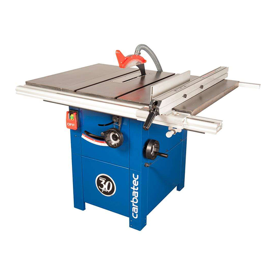
- Page 1 WARRANTY OWNERS MANUAL 10” – 250mm ENCLOSED CABINET TABLE SAW TS-C250H...
-
Page 2: Declaration Of Conformity
Declaration of Conformity Copied from CE Certificate manufactured by Laizhou Fulin Machinery Co. is in compliance with the following standards or The undersigned, F. Nispel authorised by standardisation documents inaccordance with Council Laizhou Fulin Machinery Co., Ltd.No. 275 Wenquan Directives East Road Laizhou, Shandong 261400 P.R. - Page 3 Parts Index Model Number: MJ2325D/MJ2330D 501196 10” and 501197 12” Saw Bench (Box 1 of 2) 1 off: Saw Table on upper chassis (with motor, table insert, saw blade & NVR Switch fitted) 2 off: Side Panels and Front & Back Panels 4 off: Lower Leg Columns 1 off: Side Table Extension 1 off: Dust Extraction Moulding 100mm...
- Page 4 Parts Index 501196 10” and 501197 12” Saw Bench (Box 2 of 2) 1 off: Rip Fence Assembly (partially assembled) 1 off: Rip Fence Extension 1 off: Short Rip Fence (front rail) 1 off: Short Rip Fence (back rail) Bag Containing: 2 off: ‘T’...
- Page 5 Parts index 951539 10” and 12” Sliding Table kits ( Box 2 of 2) Mitre Angle Rear Quadrant (with lift and shift handle) Table Fence Mounting Casting Mitre Angle Rip Fence 2 off: Height Adjusting Blocks 1 off: Distance Stop (with lift and shift handle) General Instructions for 230V Machines Good Working Practices/Safety The following suggestions will enable you to observe good working...
-
Page 6: General Instructions For 230V Machines
General Instructions for 230V Machines UNDER NO CIRCUMSTANCES SHOULD CHILDREN BE ALLOWED IN WORK AREAS t is good practice to leave the machine unplugged until being caught up in the rotating parts of the machine, work is about to commence, also make sure to unplug likewise, consideration should be given to the removal the machine when it is not in use, or unattended. -
Page 7: Specification
Specification TS-C250H Model AW10BSB2 AW12BSB2 Code 501196 501197 Rating Trade Trade Power 2.2kW 230V 1ph 3kW 230V 1ph Blade Dia/Bore 254 x 30mm 315 x 30mm 5/8” Blade Tilt 0-45° 0-45° Max Depth of Cut @ 45˚ 60mm 75mm Max Depth of Cut @ 90˚... - Page 8 Initial Assembly PLEASE RECYCLE ANY UNWANTED PACKAGING RESPONSIBLY Saw Body Assembly Having unpacked the boxes, put the parts and with washer and nut, only turn the nuts up finger tight components where they are readily to hand. Break at this time. (See fig 2) Locate the rear extention table down the main box by knocking the sides away (be (6), table support brackets (7), steel clamping plates (8) careful of exposed nails etc.), but leave the machine...
- Page 9 Initial Assembly With easy open access, now is a good time to fit the Fig 5 dust extraction hose. Locate the hose (4A) and the two 125mm hose clips (16). Stretch the hose out to its full length. Slip the hose clips over the ends of the hose, fit the hose to the outlet on the saw box and the dust extraction moulding and tighten the hose clips to clamp them in place.
- Page 10 Initial Assembly When everything is tightened up, the machine can Fig 16 now be tipped over, towards its blind face until it is resting on the pallet with its legs on the floor. Lift the machine upright. (See figs 13-14) Fig 12 Side Extension Table Locate four M8 x 16mm hexhead bolts and washers.
- Page 11 Initial Assembly Fitting Hand Wheels Fig 20 Locate the two hand wheels (10). Remove the Hex screw and washer from both drive shafts and place aside. Insert a square key into each machined slot on the drive shafts and slide the hand wheels onto the shafts.
- Page 12 Initial Assembly Introduce the slot in the riving knife (14) over the two centre line bolts, behind the washers and nip the bolts to just hold the riving knife against the mounting plate. Set the riving knife so its close to the blade, (gap with in 8mm). Tighten the clamping bolts securely. (See figs 23-24) Replace the saw gullet.
- Page 13 Initial Assembly There is no requirement to remove the guard. The profile of the riving knife precludes the use of the saw for slotting or grooving, and the maximum depth of cut can be achieved with the guard in place. NOTE: The positioning of the extraction hose could be a nuisance if you are cutting big boards, in such a case it is better to remove the hosing from the guard, then there is less risk getting the workpiece snagged and perhaps ‘slewing’...
- Page 14 Initial Assembly Locate the capping plates for the front rail (24B) and using the self tapping screws (24C), secure in place. (See fig 35) Set the front rail in position, remembering that it must be slightly inside the front left hand edge of the main saw table, so that the sliding table does not collide with it. Tighten ONLY the 3 bolts in the main saw table.
- Page 15 Initial Assembly Rip Fence Extention tighten to clamp the extension in place. (See fig 46) Introduce the nose of the bar (12) into the required Locate the Rip Fence Extension (21), the two M6 x ‘T’ slot in the main table. (See fig 47) 70mm ‘T’...
- Page 16 Initial Assembly it almost home. The extension should be hanging WARNING!! THE EXTENSION TABLES approximately in its correct position held by the ARE VERY HEAVY YOU WILL REQUIRE A two bolts. Introduce and almost screw home the SECOND PERSION TO HELP! other two bolts and washers.
- Page 17 Initial Assembly First remove the rip fence assembly (20) and place 501196 10” and 501197 12” safely aside, loosen both rip fence rails (32-33) and Table Extension Kits (Box 2 of 2) slide them to the right. Undo the four M8 x 30mm Locate the long Rip Fence (front rail) (32) and (back hex bolts and remove the left table.
- Page 18 Initial Assembly Fig 56 Fig 60 Screw the threaded rubber foot (28) on to the end of the support leg (27), until it’s tight. (See fig 57) Unlock the caphead clamping bolt of the support leg and allow the inner section to slide through until the foot is resting on the floor.
-
Page 19: Setting The Machine
Setting the Machine Tilt the blade fully over. Using a mitre square, set the angle of the saw to 45˚. Check that the index mark gives a corresponding reading against the scale. Adjust the pointer if necessary. Reset the blade upright, check that the angle scale reading is correct. (See figs 98-99) Fig 98 Fig 99 Pointer... - Page 20 Setting the Machine Setting the Mitre Fence Fit the small mitre fence (11) to the machine. Loosen Check that the angle is correct (and the lug is on the clamping handle (A). the correct side of the pin). Check that the indexing pointer gives the correct reading against the scale.
-
Page 21: Specific Instructions/Precautions For The Saw Bench
Setting the Machine Connect the machine to the mains supply, lift the switch shroud and give the machine a quick burst. i.e. On/Off. Check that everything is sound and feels O.K. (No knocking, scraping, belt squeal, rubbing etc.,) Give the machine a longer run, and ‘SLAP’ the Emergency switch shroud down. Check that this gives a fast and easy method of switching the machine off, without searching for the stop switch button. - Page 22 Specific Instructions/Precautions for the Saw Bench the blade ensure that the push stick is to hand, foreign objects e.g. old nails, screws, small and you use it. stones etc embedded in the material you are about to cut. If necessary take a wire brush to Remember the emphasis of the push should the timber before working.
-
Page 23: Changing The Saw Blade
Changing the Saw Blade WARNING! DISCONNECT THE MACHINE FROM THE MAINS! Raise the saw blade to it’s highest point. Remove the saw blade guard. Remove the 5 screws that secure the table insert, place carefully aside and remove the table insert. (A) Using the spanner and the tommy bar provided, put the spanner onto the flats on the nut. -
Page 24: Maintenance
Changing the Saw Blade Tighten up the saw nut, using the tommy bar Give the machine a ‘quick’ burst check ( i.e. quick to hold the shaft steady. Check the riving knife ON-OFF) to ensure everything is O.K. If everything is is aligned with the saw blade, and correctly satisfactory, continue to use the machine. - Page 34 1 year from date of sale. Carbatec Pty Ltd ABN 84 010 706 242 info@carbatec.com.au | Phone 1800 658 111 | www.carbatec.com.au...
- Page 35 Carbatec Pty Ltd ABN 84 010 706 242 info@carbatec.com.au Phone: 1800 658 111 128 Ingleston Road, Wakerley Queensland Australia 4154 www.carbatec.com.au...
Need help?
Do you have a question about the TS-C250H and is the answer not in the manual?
Questions and answers