Table of Contents
Advertisement
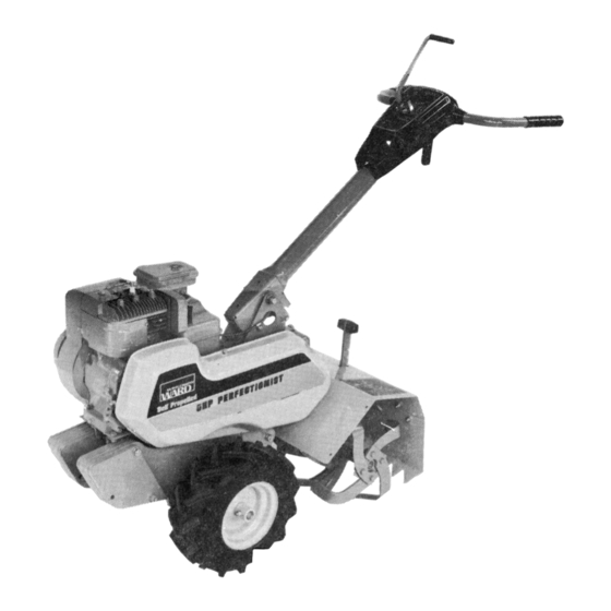
REAR TINE
TILLER
ROT A RY T ILL ER
-
ilnlu0uulllc,Pnftfl||r|0tw
orlly sptctRmW
tvt0tltlr
Tifrffibeads
are nor
pr'perlv
seated,
arr pnssure
ovbr 34 pgi can ciuie ttre ilil hilert ffi ih;
assembly
lq_a\pbde
with forielullicient
to artae iiri,iii ol Tiiii'i'ijii.iiii.
Make certain rim rs correct diarireter
and type.G.n rim, lubricat0,,rim,
,beads
:l9"t9:8"*1,'"ll'^,^{t,ttt'$eno_fl
ilvgiecotaI$iildiil;hp]"
beads.
.Do not stand ovTrffi tltffi tatrng-ffiiffi
: manufacturer's
inflation
recommendetis["-.^:::,
-. __
IMPO RTANT
READ THIS MANUAL CAREFULLY AND KEEP FOR FUTURE REFERENCE
Advertisement
Table of Contents

Related Manuals for Montgomery Ward GIL-39012B


Summary of Contents for Montgomery Ward GIL-39012B
- Page 1 ROTAR Y TILLER READ THIS MANUAL CAREFULLY AND KEEP FOR FUTURE REFERENCE ilnlu0uulllc,Pnftfl||r|0tw orlly sptctRmW pr'perlv seated, arr pnssure assembly with forielullicient lq_a\pbde Make certain rim rs correct diarireter :l9"t9:8"*1,'"ll'^,^{t,ttt'$eno_fl beads. : manufacturer's IMPORTAN T REAR TINE TILLER tvt0tltlr Tifrffibeads ovbr 34 pgi can ciuie ttre ilil hilert ffi ih;...
- Page 2 GONTENTS Generol Introduction Sofety Tips Initiol Servicing Controls ond Operotion Storting Your Rotory Tiiler Adiustments Seruicing ond Mointenqnce Storoge Tiller Ports Tiller Ports List Chqin Cose Ports Choin Cose Ports List How to Order Replocement ports IMpoRTANT! Record the unit model number ond its seriol fulure reterence when ordering repoir ports or identificotion if The monufocturer reseryes the right lo mqke chonges on ony time without notice or obtigttion.
- Page 3 GENERAL INTRODUCTION This Owneis Guide hos been especiolly prepored lo provide the informotion needed to op'eiote your ler with greoler sotisfoction. Reod this'Owne/i Guide ond the engine inslrucfions corefully. Be sure you know whot the controls ore for ond how they o[er- gte: Ilte core your tiiler requires is smoil, but'imior_ tont.
- Page 4 IN IT IAL S ERVI CING Before storling the engine, refer fo the engine in- sfructions. Be cerloin lhe the engine cronkcose is filled with the proper type oil ond thot oll en- gine service instructions hove been followed com- pletely.
- Page 5 When the handle bar is in tnansport location, fhe clufch control lever will only operofe by pulling the lever bock. This engoges the drive to the wheels ond the tiller moves forword of tronsporl speed. When re- leosed, fhe control lever refurns to neulrol. DEPTH CONTROL LEVER GAUTION: Do nor adiust rilling depth wfth rhe tines rotatang.
- Page 6 ADJUSTMENTS CAUTION: Never ofiempt to moke-odjustments on fhe liller while the engine is running. Alwoys stop lhe engine ond disconnecl the wirelrom tn6 spoit plug before ottempling to moke odjustments. BELT ADJUSTMENTS TINE DBIVE BELT The tine drive belt, which is the outer be[, is odjusted by l9_9s9ning the ctomp cop screws (Figuie 4) onct roto_ ang me enflre cose qnd tine ossembly.
- Page 7 HANDLE CONTROL LEVER ADJUSTMENT The hondle control odjustmenl (Figure 7) hos been set for proper operotion ond should not need to be odiusfed. Should the hondle control lever (Figure 7) become loose ofter mony hours of operolion, tighlen the odjustmenl nul only enough lo eliminote ony ex- cess movement in the hondle confrol lever.
- Page 8 SERVIGING AND MAINTENANGE The besf ossuronce you hove of geiling the mosl de_ pendoble service from your tiller is to keep the unit cleon, free of rust, ond well lubricoted. Check bolts often lo be sure they ore kept tight. When the tiller is not being used, it should be stored in o dry ploce out of lhe weother.
- Page 9 lilll, To odd lubricont to eilher choin cose it is necessory to tip liller on its lefi side lo expose tevel ptugs of eocn cose. Add sufficient teod bose (Ep) SAE taO neovy duty oil (Port 4890) to bring to propdr oit tevet. 3.
- Page 10 tl8:g!\|rNG R|N-G/ \_- -__--.---IDLER BEIT REPLACEMENT The bells on this tiller.were specificolly designed enginee.red to provide long, trouble_free service. belt replocement is requlred, orOe, ine port shown in the ports list section of thii rn6nuot, sure you hove o belt thot will provide lhe liie service reguired.
- Page 11 STOBAGE For short lerm storoge, cleon the In o dry ploce. lf tiller is not lo be used for on extended period time, service tiller completely onO Ji"re it' in ploce. 1 Feler to the engine instructions for engine storoge inslructions.
- Page 12 HANDLE & CONTROL PARTS AL-q o.,-@ ^"-?t"...
- Page 13 HANDLE & CONTROLS PARTS LIST R E F . PART LET. N O. 20 04 69 Tun n el A sse mb ly 200470 Handle Assembly 1'1 83 Gr ip.. 200612 Slide . 2 00 1 1 0 Sp rin g 20 00 6 6 Co ntr o l R od ..
- Page 14 .B P ;tr^ffieiSi: 'l:a- t-ca 22tgffiD #tury 6a-6 M____-_ FRAME AND DRIUE ./fl- a:,t -;^A 9@/---,"u '@ft{ t7"30,-- r r€ " -BZ,6\}-V PARTS €[--cl '/cL ,fu'"'o -6 ,i^ %c=s ==Eg CANS OFTOUCH-UP SPRAY PAINTARE AVAILABLE BY ORDERING: ..Gr ay Pa rt No.13 938 .
- Page 15 FRAME AND DRIVE PARTS LIST Ref. Part Let. 208139 Frame Assembly - R.H. 2O814O Frame Assembly - L.H. 2O OO 71 C o unterWeig ht ... 2O OA 7 8 C o unterWeig ht ... 200165 Depth ControlAssembly 208810 Sk id As semb ly..2OO184 Support Assembly 24897 Handle...
- Page 16 GHAIN CASE PABTS Io reploce oll choin cose seols ond doskets order Port No. 89428. To reploce entile choin cose less lines drder Pod No. 89429'...
- Page 17 GHAIN GASE PARTS LIST REF. PART LET. N O. 208162 Chain Case Ass'y. - R.H. w/Bearings ..208163 Chain Case Ass'y. - L.H. w/Bearings 1054 Seal - Tine Shaft. . 208176 Seal - InputShaft . 208052 Gasket 208051 Chain - Lcwer .
- Page 18 OPERATING AND MAINTENANCE DO NOT RUN ENGTNE AT EXCESSIVE SPEEDS. Operating an engine at excessive speeds increases the hazard of personal injury. DO NO T T AM PER W I TH PARTS WH ICH M AY IN C R E A SE TH E GOV E R N E D SP E E D . For rotary lawnmower safety, A.N.S.l.
- Page 19 SPARK PL UG 11 0 VOLT S TAR TE R OIL FIL L PL UG FORM NO. 270106-3/79 PR INT ED IN U.S. A. B EFOR E STA RTI NG REA D THE OP ERA TING INS TRUCTI O NS O F TH E EOUIP MENT THIS E NGINE P O WER S Use a high q uali ty deterge nt oil classifi ed "...
- Page 20 STARTING S tar t , st or e and fu el eng ine in a le vel po sitio n. E ngin e m ay be e qu ipp ed w i th e ith e r E N GI NE - Choke-A-Matic or Lever-Trol controls.
- Page 21 MAI N T E N A N CE CHECK OIL LEVEL regularly - after each five hours ol operatio-n-trSFE orL LEVEL ts MAtNTAINED. CHANGE OIL after first five hours of operation. Thereafter change every 25 hours of operation. Remove oil drain plug a n d d r ain oi l whi l e e ngi ne i s w ar m.
- Page 22 Grass, chaff or dirt may CLEAN COOLING SYSTEII - the air cooling system, especially after prolonged service cutting dry grass. Yearly or every 100 hours, whichever occurs first, remove the blower housing and clean the areas shown -to avoid over- speeding, overheating and engine damage.
- Page 23 men t on wh ich th e e ngin e is u se d, s pe ci fi es th e top g ov er ne d no l o ad s pee d at wh ich th e en gi n e ma y be oper a t ed.
Need help?
Do you have a question about the GIL-39012B and is the answer not in the manual?
Questions and answers