Table of Contents
Advertisement
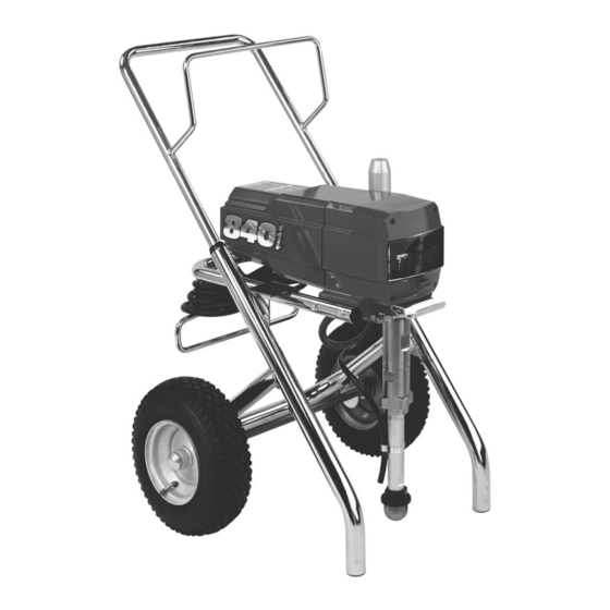
Do not use this equipment before reading this manual!
840
Model Number:
High Rider Bare
High Rider Complete
Low Rider Bare
Low Rider Complete
Printed in the U. S. A.
i
Airless Sprayer
International Model
800-130-CE
800-131-CE
800-132-CE
800-133-CE
Owner's Manual
For professional use only
NOTE: This manual contains important warnings
NOTE: This manual contains important warnings
and instructions. Please read and retain for
and instructions. Please read and retain for
reference.
reference.
0802 © 2002 Titan Tool Inc. All rights reserved. Form No. 313-1797, REV A
Advertisement
Table of Contents

Related Manuals for Titan 840i


Summary of Contents for Titan 840i
- Page 1 Do not use this equipment before reading this manual! Model Number: High Rider Bare High Rider Complete Low Rider Bare Low Rider Complete Printed in the U. S. A. Airless Sprayer International Model 800-130-CE NOTE: This manual contains important warnings NOTE: This manual contains important warnings 800-131-CE 800-132-CE...
-
Page 2: Table Of Contents
Table of Contents Safety Precautions ...2 Français ...14 Español ...16 General Description ...4 Operation ...4 Setup ...4 Preparing to Paint ...4 Painting ...5 Electronic Pressure Control Indicators ...5 Pressure Relief Procedure ...6 Spraying ...6 Spraying Technique ...6 Practice ...7 Cleanup ...7 Cleaning the Spray Tip ...7 Maintenance...8 General Repair and Service Notes...8... -
Page 3: Earthing Instructions
9. Attention! Please observe the following when working inside and outside: No solvent gasses should be carried to the unit. No solvent gasses should form near the unit. Set up the unit on the opposite side to the object being sprayed. When spraying outdoors, take the wind direction into account. -
Page 4: Product View And Parts
General Description This airless sprayer is a precision power tool used for spraying many types of materials. Read and follow this instruction manual carefully for proper operating instructions, maintenance, and safety information. Pressure Control Knob Electronic Pressure Control Indicators Oil Cup Circuit Breaker Fluid... -
Page 5: Painting
7. Move the PRIME/SPRAY valve up to the SPRAY position. 8. Turn the unit on and set the pressure to minimum by turning the pressure control knob to the “Min PSI” setting in the yellow zone. 9. Unlock the gun by turning the gun trigger lock to the unlocked position. -
Page 6: Pressure Relief Procedure
Solid Yellow When the pressure indicator is solid yellow, the sprayer is operating between 14 and 124 bar (200 and 1800 PSI). A solid yellow pressure indicator means: • The sprayer is at the proper pressure setting for spraying stain, lacquer, varnish, and multi-colors. •... -
Page 7: Practice
For corners and edges, split the center of the spray pattern on the corner or edge and spray vertically so that both adjoining sections receive approximately even amounts of paint. When spraying with a shield, hold it firmly against the surface. Angle the spray gun slightly away from the shield and toward the surface. -
Page 8: Maintenance
Maintenance WARNING Before proceeding, follow the Pressure Relief Procedure outlined previously in this manual. Additionally, follow all other warnings to reduce the risk of an injection injury, injury from moving parts or electric shock. Always unplug the sprayer before servicing! General Repair and Service Notes The following tools are needed when repairing this sprayer: Phillips Screwdriver... -
Page 9: Replacing The Transducer
7. Loosen and remove the three motor mounting screws. 8. Pull the motor out of the gearbox housing. 9. Inspect the armature gear on the end of the motor for damage or excessive wear. If this gear is completely worn out, replace the front end bell assembly. 10. -
Page 10: Servicing The Fluid Section
Servicing the Fluid Section Use the following procedures to service the valves and repack the fluid section. Perform the following steps before performing any maintenance on the fluid section. 1. Loosen and remove the four front cover screws. Remove the front cover. 2. -
Page 11: Replacing The Filters
15. Insert the spacer on top of the upper packing. 16. Thread the upper seal retainer into the upper housing and torque to 25-30 ft. lbs. 17. Insert the lower packing partially into the bottom of the upper housing so that the side that has the o-ring closest to the face of the packing faces up. -
Page 12: Troubleshooting
Problem Cause The unit will not run. 1. The unit is not plugged in. 2. Tripped breaker. 3. The pressure is set too low (pressure 4. Faulty or loose wiring. 5. Excessive motor temperature. The unit will not prime. 1. The PRIME/SPRAY valve is in the 2. - Page 13 Problem Cause Excessive surge at the spray 1. Wrong type of airless spray hose. gun. 2. The spray tip worn or too large. 3. Excessive pressure. Poor spray pattern. 1. The spray tip is too large for the 2. Incorrect pressure setting. 3.
-
Page 14: Consignes De Sécurité
Consignes de sécurité Ce manuel contient des informations qu'il faut lire et comprendre avant d'utiliser l'appareil. En cas d'accès à une zone comportant l'un des symboles suivants, faire très attention et veiller à respecter les mises en garde. AVERTISSEMENT Ce symbole avertit d'un danger potentiel pouvant infliger des blessures graves ou la mort. -
Page 15: Directives De Mise À La Terre
14. L’action sur la gâchette produit une force de recul sur la main tenant le pistolet. La force de recul du pistolet est particulièrement élevée avec buse démontée et réglage maximum de la pompe Airless à haute pression. Pour cette raison, en cas de nettoyage sans buse, régler la pompe à... -
Page 16: Precauciones De Seguridad
Precauciones de Seguridad Este manual contiene información que tiene que leerse y entenderse antes de utilizar el equipo. Cuando se encuentre en una área que tenga uno de los siguientes símbolos, esté muy atento y asegúrese que tiene en cuenta la seguridad. ADVERTENCIA Estos símbolos indican un peligro potencial que puede causar graves daños o pérdidas humanas. -
Page 17: Instrucciones De Puesta A Tierra
13. Limpieza de la unidad. Nunca debe utilizarse una boquilla gruesa para pulverizar la unidad. En particular, nunca debe utilizarse un limpiador de alta presión o limpiador a vapor de alta presión. Hay peligro de que el agua penetre en la unidad y cause un cortocircuito. -
Page 18: Parts Listings
Parts List Main Assembly Item Part # Description 800-600 Cart assembly...1 ---------- Drive assembly ...1 761-178 Screw...4 800-324 Pail hook ...1 763-551 Lock washer...2 858-625 Screw...2 800-328 Knock-off nut...1 800-300 Fluid section assembly ...1 451-241 Siphon tube...1 730-334 Hose clamp...1 710-046 Inlet screen ...1 800-268... -
Page 19: Drive Assembly
Drive Assembly Item Part # Description 800-078 Electronic cover ...1 800-205 Screw...3 800-224 Motor assembly, 1.1 HP ...1 800-256 Front end bell assembly ...1 800-525 Housing gasket ...1 800-541 Shroud gasket...1 800-261 1st stage gear assembly...1 800-262 2nd stage gear asembly ...1 800-259 Front gearbox assembly ...1 800-510... -
Page 20: Fluid Section Assembly
Fluid Section Assembly (P/N 800-300) Install upper packing with raised lip facing down. Raised Lip Closer Install lower packing with the side that has the o-ring closest to the top of the packing facing up. NOTE: When repacking the fluid section, make sure the raised lip on the bottom of the lower packing is fully outside the packing around the piston rod after insertion of... -
Page 21: High Rider Cart
Item Part # Description 800-325 Upper seal retainer ...1 800-327 Spacer ...1 800-248 Upper packing assembly ...1 800-351 Upper housing ...1 800-250 Lower packing assembly ...1 800-354 Wear ring ...1 800-332 O-ring, black ...2 800-333 Back-up ring, white ...2 800-352 Lower housing ...1 800-246 Piston rod...1... -
Page 22: Siphon Set Assembly (Low Rider)
700-742 Tie wrap (not shown) ...3 710-204 Siphon hose assembly (includes items 2–6) ...1 Labels Part # Description 313-1651 840i logo label 313-1673 Warning label (injection/explosion) 313-1847 Shock hazard label 313-1658 “Press to Reset” label 313-1848 Pressure control knob label... -
Page 23: Prime/Spray Assembly
PRIME/SPRAY Valve Assembly (P/N 800-915) Item Part # Description 700-823 Dowel pin ...1 700-537 Gasket ...1 222-012 O-ring, Teflon ...1 221-012 O-ring, Viton...1 800-924 Valve housing ...1 700-697 Valve handle ...1 700-759 Groove pin ...1 700-721 O-ring, Viton...1 700-250 Valve stem ...1 800-926 Spring ...1 700-248... -
Page 24: Warranty
Warranty Titan Tool, Inc., (“Titan”) warrants that at the time of delivery to the original purchaser for use (“End User”), the equipment covered by this warranty is free from defects in material and workmanship. Titan’s obligation under this warranty is limited to replacing or repairing without charge those parts which, to Titan’s reasonable satisfaction, are shown to be defective within twenty-five (25) months after sale to the End User.
Need help?
Do you have a question about the 840i and is the answer not in the manual?
Questions and answers