Table of Contents
Advertisement
Advertisement
Chapters
Table of Contents

Related Manuals for Beckhoff BK11 0 Series


Summary of Contents for Beckhoff BK11 0 Series
- Page 1 Documentation BK11x0, BK1250 EtherCAT Bus Coupler Version: Date: 25.04.2017...
- Page 3 Product overview - EtherCAT Bus Coupler Product overview - EtherCAT Bus Coupler BK1120, BK1150 [} 14] - EtherCAT Bus Coupler for standard Bus Terminals BK1250 [} 15] - "Compact" coupler between E-bus and K-bus terminals BK11x0, BK1250 Version: 4.1...
-
Page 4: Table Of Contents
Version identification of EtherCAT devices.................. 9 3 Product overview............................. 14 Introduction ........................... 14 Technical data .......................... 16 4 Basic principles ............................ 17 System properties......................... 17 The Beckhoff Bus Terminal system .................... 20 CoE Interface.......................... 21 EtherCAT State Machine ...................... 25 LEDs and connection........................ 28 4.5.1 LEDs .......................... 28 4.5.2... - Page 5 Table of contents 6.4.9 Object description ...................... 64 6.4.10 Mapping the Bus Terminals ..................... 74 6.4.11 Process image example.................... 75 KS2000 configuration software..................... 76 6.5.1 Example: parameterization with the KS2000 configuration software ....... 76 7 Error handling and diagnosis......................... 80 Error messages to the EtherCAT master.................. 80 8 Appendix .............................. 81 General operating conditions......................
- Page 6 Table of contents Version: 4.1 BK11x0, BK1250...
-
Page 7: Foreword
The TwinCAT Technology is covered, including but not limited to the following patent applications and patents: EP0851348, US6167425 with corresponding applications or registrations in various other countries. ® EtherCAT is registered trademark and patented technology, licensed by Beckhoff Automation GmbH, Germany Copyright © Beckhoff Automation GmbH & Co. KG, Germany. -
Page 8: Safety Instructions
All the components are supplied in particular hardware and software configurations appropriate for the application. Modifications to hardware or software configurations other than those described in the documentation are not permitted, and nullify the liability of Beckhoff Automation GmbH & Co. KG. Personnel qualification This description is only intended for trained specialists in control, automation and drive engineering who are familiar with the applicable national standards. -
Page 9: Documentation Issue Status
• Object descriptions amended • Technical data added • First preliminary version Version identification of EtherCAT devices Designation A Beckhoff EtherCAT device has a 14-digit designation, made up of • family key • type • version • revision Example... - Page 10 Production lot/batch number/serial number/date code/D number The serial number for Beckhoff IO devices is usually the 8-digit number printed on the device or on a sticker. The serial number indicates the configuration in delivery state and therefore refers to a whole production batch, without distinguishing the individual modules of a batch.
-
Page 11: Fig. 1 El5021 El Terminal, Standard Ip20 Io Device With Batch Number And Revision Id (Since 2014/01)
Foreword • IP67: EtherCAT Box • Safety: TwinSafe • Terminals with factory calibration certificate and other measuring terminals Examples of markings Fig. 1: EL5021 EL terminal, standard IP20 IO device with batch number and revision ID (since 2014/01) Fig. 2: EK1100 EtherCAT coupler, standard IP20 IO device with batch number Fig. 3: CU2016 switch with batch number BK11x0, BK1250 Version: 4.1... -
Page 12: Fig. 4 El3202-0020 With Batch Numbers 26131006 And Unique Id-Number 204418
Foreword Fig. 4: EL3202-0020 with batch numbers 26131006 and unique ID-number 204418 Fig. 5: EP1258-00001 IP67 EtherCAT Box with batch number 22090101 and unique serial number 158102 Fig. 6: EP1908-0002 IP76 EtherCAT Safety Box with batch number 071201FF and unique serial number 00346070 Fig. 7: EL2904 IP20 safety terminal with batch number/date code 50110302 and unique serial number 00331701 Version: 4.1... -
Page 13: Fig. 8 Elm3604-0002 Terminal With Id Number (Qr Code) 100001051 And Unique Serial Number 44160201
Foreword Fig. 8: ELM3604-0002 terminal with ID number (QR code) 100001051 and unique serial number 44160201 BK11x0, BK1250 Version: 4.1... -
Page 14: Product Overview
BK1120, BK1150 Fig. 9: Bus Couplers BK1120 and BK1150 The Bus Couplers BK1120 and BK1150 connect EtherCAT with the tried and tested Beckhoff K-bus terminals (KLxxx). A station consists of a BK1120 / BK1150 Bus Coupler, any number of K-bus terminals (up to 64, or up to 255 with K-bus extension) and a bus end terminal. -
Page 15: Fig. 10 Bk1250
Product overview BK1250 Fig. 10: BK1250 Fig. 11: K-bus_E-bus The BK1250 is a "Bus Coupler in the terminal housing" for mixed application of EtherCAT terminals (ELxxxx) and standard Bus Terminals (KLxxxx) in a bus station. It allows implementation of compact and cost-effective control solutions. -
Page 16: Technical Data
Product overview Technical data Technical data BK1120 BK1150 BK1250 Task in the EtherCAT system Coupling of standard Bus Terminals (KLxxxx) to 100BASE-TX EtherCAT networks Number of K-bus terminals 64 (255 with K-bus extension interface KL9020 and KL9050) Max. number of bytes, 1024 bytes input and 1024 bytes output fieldbus Digital peripheral signals... -
Page 17: Basic Principles
Basic principles Basic principles System properties Protocol The EtherCAT protocol is optimized for process data and is transported directly within the Ethernet frame thanks to a special Ether-type. It may consist of several sub-telegrams, each serving a particular memory area of the logical process images that can be up to 4 gigabytes in size. The data sequence is independent of the physical order of the Ethernet terminals in the network;... -
Page 18: Fig. 13 Ethercat Topology
Basic principles Topology Line, tree or star: EtherCAT supports almost any topology. The bus or line structure known from the fieldbuses thus also becomes available for Ethernet. Particularly useful for system wiring is the combination of line and junctions or stubs. The required interfaces exist on the couplers; no additional switches are required. - Page 19 In addition to the new Bus Terminals with E-Bus connection (ELxxxx), all Bus Terminals from the familiar standard range with K-bus connection (KLxxxx) can be connected via the BK1120 or BK1250 Bus Coupler. This ensures compatibility and continuity with the existing Beckhoff Bus Terminal systems. Existing investments are protected.
-
Page 20: The Beckhoff Bus Terminal System
Bus Couplers for all usual bus systems The Beckhoff Bus Terminal system unites the advantages of a bus system with the possibilities of the compact series terminal. Bus Terminals can be driven within all the usual bus systems, thus reducing the controller parts count. -
Page 21: Coe Interface
Basic principles Potential feed terminals for isolated groups The operating voltage is passed on to following terminals via three power contacts. You can divide the terminal strip into arbitrary isolated groups by means of potential feed terminals. The potential feed terminals play no part in the control of the terminals, and can be inserted at any locations within the terminal strip. -
Page 22: Fig. 14 "Coe Online " Tab
This is recommended for modifications while the system is running or if no System Manager or operating staff are available. If slave CoE parameters are modified online, Beckhoff devices store any changes in a fail-safe manner in the EEPROM, i.e. the modified CoE parameters are still available after a restart. The situation may be different with other manufacturers. -
Page 23: Fig. 15 Startup List In The Twincat System Manager
Startup list Changes in the local CoE list of the terminal are lost if the terminal is replaced. If a terminal is replaced with a new Beckhoff terminal, it will have the default settings. It is therefore ad- Note visable to link all changes in the CoE list of an EtherCAT slave with the Startup list of the slave, which is processed whenever the EtherCAT fieldbus is started. -
Page 24: Fig. 16 Offline List
Basic principles Online/offline list While working with the TwinCAT System Manager, a distinction has to be made whether the EtherCAT device is "available", i.e. switched on and linked via EtherCAT and therefore online, or whether a configuration is created offline without connected slaves. In both cases a CoE list as shown in Fig. -
Page 25: Ethercat State Machine
This is generally written as 0x80n0. Detailed information on the CoE interface can be found in the EtherCAT system documentation on the Beckhoff website. EtherCAT State Machine The state of the EtherCAT slave is controlled via the EtherCAT State Machine (ESM). Depending upon the state, different functions are accessible or executable in the EtherCAT slave. -
Page 26: Fig. 18 States Of The Ethercat State Machine
Basic principles Fig. 18: States of the EtherCAT State Machine Init After switch-on the EtherCAT slave in the Init state. No mailbox or process data communication is possible. The EtherCAT master initializes sync manager channels 0 and 1 for mailbox communication. Pre-Operational (Pre-Op) During the transition between Init and Pre-Op the EtherCAT slave checks whether the mailbox was initialized correctly. - Page 27 Basic principles Boot In the Boot state the slave firmware can be updated. The Boot state can only be reached via the Init state. In the Boot state mailbox communication via the file access over EtherCAT (FoE) protocol is possible, but no other mailbox communication and no process data communication.
-
Page 28: Leds And Connection
Basic principles LEDs and connection 4.5.1 LEDs After switching on, the Bus Coupler immediately checks the connected configuration. Error-free start-up is signaled by the red LED I/O ERR being extinguished. If the I/O ERR LED blinks, an error in the area of the terminals is indicated. -
Page 29: Fig. 20 Diagnostic Leds At Bus Coupler Bk1150
Basic principles Fig. 20: Diagnostic LEDs at Bus Coupler BK1150 The diagnostic LEDs for the BK1250 are arranged as shown in Fig. Diagnostic LEDs at Bus Coupler BK1250. Fig. 21: Diagnostic LEDs at Bus Coupler BK1250 LEDs for power supply diagnostics Display State Description POWER... - Page 30 Basic principles Diagnostic LEDs for the EtherCAT State Machine/PLC Display State Description green off Init The Bus Coupler is in initialization state flashing Pre-Operational The Bus Coupler is in pre-operational state single flash Safe-Operational The Bus Coupler is in safe-operational state Operational The Bus Coupler is in operational state flickers...
- Page 31 Basic principles LED red; Error code ar- Description Remedy I/O-Error gument Persistent EMC problems • Check power supply for undervoltage or overvoltage peaks continuou • Implement EMC measures s flashing • If a K-bus error is present, it can be localized by a restart of the coupler (by switching it off and then on again) 1 pulse...
-
Page 32: Connection Bk1120 And Bk1150
Basic principles 4.5.2 Connection BK1120 and BK1150 Fig. 22: BK1120, BK1150 Connection Table 1: Connection Terminal point Description Name +24 V Us Power supply for Bus Coupler and E-bus electronics +24 V Up Power supply for power contacts (internally connected to terminal point 6) 0 V Up Power supply for power contacts (internally connected to terminal point 7) PE connection (internally connected to terminal point 8) -
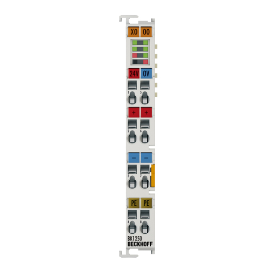
Page 33: Connection Bk1250
Basic principles 4.5.3 Connection BK1250 Fig. 23: BK1250 Connection Table 2: Connection Terminal point Description Name +24 V Us Power supply for Bus Coupler and E-bus electronics +24 V Up Power supply for power contacts (internally connected to terminal point 6) 0 V Up Power supply for power contacts (internally connected to terminal point 7) PE connection (internally connected to terminal point 8) 0 V Us... -
Page 34: Mounting And Wiring
Each assembly must be terminated at the right hand end with an EL9011 bus end cap, to ensure the protection class and ESD protection. Fig. 24: Spring contacts of the Beckhoff I/O components Version: 4.1 BK11x0, BK1250... -
Page 35: Installation On Mounting Rails
Mounting and wiring Installation on mounting rails Risk of electric shock and damage of device! Bring the bus terminal system into a safe, powered down state before starting installation, disassembly or wiring of the Bus Terminals! WARNING Assembly Fig. 25: Attaching on mounting rail The Bus Coupler and Bus Terminals are attached to commercially available 35 mm mounting rails (DIN rails according to EN 60715) by applying slight pressure: 1. -
Page 36: Fig. 26 Disassembling Of Terminal
Mounting and wiring Disassembly Fig. 26: Disassembling of terminal Each terminal is secured by a lock on the mounting rail, which must be released for disassembly: 1. Pull the terminal by its orange-colored lugs approximately 1 cm away from the mounting rail. In doing so for this terminal the mounting rail lock is released automatically and you can pull the terminal out of the bus terminal block easily without excessive force. -
Page 37: Fig. 27 Power Contact On Left Side
Mounting and wiring Fig. 27: Power contact on left side Possible damage of the device Note that, for reasons of electromagnetic compatibility, the PE contacts are capacitatively coupled to the mounting rail. This may lead to incorrect results during insulation testing or Attention to damage on the terminal (e.g. -
Page 38: Installation Instructions For Enhanced Mechanical Load Capacity
Mounting and wiring Installation instructions for enhanced mechanical load capacity Risk of injury through electric shock and damage to the device! Bring the Bus Terminal system into a safe, de-energized state before starting mounting, disassembly or wiring of the Bus Terminals! WARNING Additional checks The terminals have undergone the following additional tests:... -
Page 39: Installation Positions
Mounting and wiring Installation positions Constraints regarding installation position and operating temperature range Please refer to the technical data for a terminal to ascertain whether any restrictions re- garding the installation position and/or the operating temperature range have been speci- Attention fied. -
Page 40: Power Supply, Potential Groups
Mounting and wiring Fig. 29: Other installation positions Power supply, potential groups Bus Coupler power supply The Bus Couplers require a 24 V DC supply for their operation. The connection is made by means of the upper spring-loaded terminals labelled 24 V and 0 V. The supply voltage is used by the Bus Coupler electronics and for direct voltage generation for the E-bus. -
Page 41: Ethernet Cable
Mounting and wiring Power contacts On the right hand face of the Bus Coupler there are three spring contacts for the power contact connections. The spring contacts are hidden in slots so that they can not be accidentally touched. By attaching a Bus Terminal the blade contacts on the left hand side of the Bus Terminal are connected to the spring contacts. - Page 42 Mounting and wiring 10BaseT Describes a twisted pair cable for 10 Mbaud. The network here is constructed as a star. It is no longer the case that every device is attached to the same medium. This means that a broken cable no longer results in failure of the entire network.
-
Page 43: Ethercat Wiring
Due to automatic cable detection (auto-crossing) symmetric (1:1) or cross-over cables can be used between EtherCAT devices from Beckhoff. The following Beckhoff cables and connectors are suitable for application in EtherCAT systems: • ZB9010 (Industrial Ethernet/EtherCAT cable, fixed installation, CAT 5e, 4-core) •... -
Page 44: Atex - Special Conditions (Extended Temperature Range)
• EN 60079-0:2012+A11:2013 • EN 60079-15:2010 Marking The Beckhoff fieldbus components with extended temperature range (ET) certified for potentially explosive areas bear the following marking: II 3G KEMA 10ATEX0075 X Ex nA IIC T4 Gc Ta: -25 … 60°C II 3G KEMA 10ATEX0075 X Ex nC IIC T4 Gc Ta: -25 … 60°C Version: 4.1... -
Page 45: Atex Documentation
Notes about operation of the Beckhoff terminal systems in potentially explo- sive areas (ATEX) Pay also attention to the continuative documentation Note Notes about operation of the Beckhoff terminal systems in potentially explosive areas (ATEX) that is available in the download area of the Beckhoff homepage http:\\www.beckhoff.com! BK11x0, BK1250... -
Page 46: Parameterization And Commissioning
Parameterization and commissioning Parameterization and commissioning Start-up behavior of the Bus Coupler Immediately after being switched on, the Bus Coupler checks, in the course of a self test, all the functions of its components and the communication on the K-bus/E-bus. The red I/O LED blinks while this is happening After completion of the self-test, the Bus Coupler starts to test the attached Bus Terminals (the "Bus Terminal Test"), and reads in the configuration. -
Page 47: Fig. 33 Advanced Distributed Clocks Settings In The Ethercat Master
Parameterization and commissioning Once of these local clocks is the reference clock, based on which all other clocks are synchronized. See also explanatory notes in the Basic EtherCAT documentation. The reference clock must be the first DC-capable EtherCAT slave. By default TwinCAT therefore selects the first DC-capable device as reference clock. This is shown (and can be modified by the user) under advanced properties of the EtherCAT master. -
Page 48: Kl Register Communication
Parameterization and commissioning Fig. 34: TwinCAT setting for using this component as reference clock Activation of Distributed Clocks support The (synchronization) procedure described here is only successful for the components de- scribed above. The checkboxes can be set for other components, too, although the hard- Note ware does not support this function, unless specified in the respective documentation. -
Page 49: Fig. 35 Register Access On Kl Terminals
◦ Internal ADS. ◦ External via a serial RS232 COM cable or a USB cable. Both are available from Beckhoff. A KS2000 interface at the coupler (e.g. BK1120) is a prerequisite for external access. -
Page 50: Configuration Of Kl Terminals Via Ethercat
Parameterization and commissioning 6.3.2 Configuration of KL terminals via EtherCAT The following is an explanation of how register communication with the KL terminals is parameterized during the EtherCAT start-up. This ensures that the KL terminal used always contains the desired register set, even if the terminal (hardware) is exchanged, because the register data is written to the KL terminal again at the next start-up of the system or EtherCAT. -
Page 51: Fig. 36 Insert Dialog
Parameterization and commissioning Example TwinCAT 2:11 b1539 and a BK1120 with firmware B8 were used in the following example. In an existing configuration (scanned or manually created), the user scaling (offset) of the KL3314 is to be changed in the startup list of the BK1120 coupler in order to ensure that the desired scaling is also saved in the terminal in the event of the terminal being exchanged. -
Page 52: Fig. 37 Data Entry
Parameterization and commissioning Fig. 37: Data entry The complete entry is shown in Fig. Entry. Fig. 38: Entry Since the code word was used, it must also be reset in order to complete the terminal access. Fig. 39: Complete terminal access More extensive register access is possible, if required, see Fig. Access to two KL terminals. In this case, two KL2541s with the numbers 3 and 4 will be parameterized in the startup phase. -
Page 53: Online Parameterization Of Kl Terminals Via Coe
Parameterization and commissioning Fig. 40: Access to two KL terminals 6.3.3 Online parameterization of KL terminals via CoE In the same way as with the CoE startup entry (CANopen over EtherCAT), online access to a KL terminal is also possible via the CoE directory of the BK11x0/BK1250 EtherCAT coupler used. Using this route, access to the coupler-internal tables or to the registers in the terminals is possible. -
Page 54: Fig. 41 Online Coe Directory Of The Bk11X0
0x4280ff, only works for KL terminals with register communication. If a terminal num- Note ber is specified in CoE object 0x427F: - which does not exist - whose terminals do not feature register communication the System Manager logger window shows "SDO Abort". Example Download (http://infosys.beckhoff.com/content/1033/bk11x0_bk1250/Resources/zip/2180724363.zip) Version: 4.1 BK11x0, BK1250... -
Page 55: Online Parameterization Of Kl Terminals Via Aoe
Parameterization and commissioning In this example program (TwinCAT 2.11, BK1120 with firmware 08), AoE and CoE register communication with a KL3314 (thermocouple terminal) is executed in the PLC. Here, register R34 (user scaling, offset) in Channel 1 is repeatedly incremented - success can be verified with the KS2000 software or via the visualization page;... -
Page 56: Beckhoff Coupler Tables
INIT-OP transition. 6.3.5 Beckhoff coupler tables The Beckhoff BK/BCxxxx Fieldbus Couplers feature internal information lists referred to as tables that are identified by unique numbers. The BK11x0/BK1250 maps these tables in its CoE directory, see Object overview [} 64]. -
Page 57: Fig. 43 Table 9 With Terminal Type
Parameterization and commissioning Fig. 43: Table 9 with terminal type SubIndex 1 is the "name" of the coupler itself, the terminals follow from subindex 2. Subindex 0 contains the number of terminals that were found. Since the subindex 1 contains the coupler name itself, the value in subindex 0 corresponds to the number of terminals, including the KL9010. -
Page 58: Twincat System Manager
Parameterization and commissioning TwinCAT System Manager 6.4.1 BK1120, BK1150 - configuration overview In the TwinCAT System Manager, in Config mode under Devices enter the BK1120 / BK1150 as EtherCAT device (Fig. TwinCAT tree showing BK1120 as example). Any Bus Couplers already connected to the network can also be read. -
Page 59: Bk1250 - Configuration Overview
Parameterization and commissioning 6.4.2 BK1250 - configuration overview The BK1250 can be added in the TwinCAT System Manager (Config mode) as a further box under a corresponding coupler (e.g. EK1100) by right-clicking in the terminal network (Fig. TwinCAT tree BK1250). If the Bus Coupler is already integrated in the network, it is automatically added as a box during scanning. -
Page 60: Inputs - Configuration Overview
Parameterization and commissioning 6.4.3 Inputs - configuration overview CouplerState, "Online" tab Display of general coupler errors. Fig. 46: CouplerState, "Online" tab 6.4.4 Outputs - configuration overview CouplerCtrl, "Online" tab Display of K-bus errors or deactivation of outputs. Version: 4.1 BK11x0, BK1250... -
Page 61: Status Of The Working Counter (Wc State) - - Configuration Overview
Parameterization and commissioning Fig. 47: CouplerCrtl, "Online" tab 6.4.5 Status of the working counter (Wc state) - - configuration overview WCstate, "Online" tab Boolean variable indicating the working counter status of coupler. An invalid working counter (value: 1) is displayed if invalid data were transferred by the EtherCAT slave controller. BK11x0, BK1250 Version: 4.1... -
Page 62: Online Status (Info Data) - Configuration Overview
Parameterization and commissioning Fig. 48: WCstate, "Online" tab 6.4.6 Online status (info data) - configuration overview State, "Online" tab Indicates the online status of the coupler. Fig. 49: State, "Online" tab Version: 4.1 BK11x0, BK1250... -
Page 63: Ads Address (Adsaddr) - Configuration Overview
Parameterization and commissioning Value Description 0x___1 Slave in 'INIT' state 0x___2 Slave in 'PREOP' state 0x___3 Slave in 'BOOT' state 0x___4 Slave in 'SAFEOP' state 0x___8 Slave in 'OP' state 0x001_ Slave signals error 0x002_ Invalid vendorId, productCode... read 0x004_ Initialization error occurred 0x010_ Slave not present... -
Page 64: Ethercat Cycle Time - Configuration Overview
Parameterization and commissioning 6.4.8 EtherCAT cycle time - configuration overview The EtherCAT cycle time with which the couplers can be operated should be considered in conjunction with the achieved K-bus cycle time. The cycle time achieved with the K-bus terminals is shown in the BK1250 tab (or BK1120 / BK1150). - Page 65 Parameterization and commissioning Index 1018 Identity object Index (hex) Name Meaning Flags Default 1018:0 Identity object Length of this object 1018:01 Vendor id Vendor ID of the EtherCAT slave 0x00000002 (2 1018:02 Product code Product code of the EtherCAT slave 0x04602C22 (73411618 1018:03...
- Page 66 Parameterization and commissioning Index 1C00 SM type Index (hex) Name Meaning Flags Default 1C00:0 Sync Manager Type Length of this object 1C00:01 Subindex 001 Sync manager, parameter 1 0x01 (1 1C00:02 Subindex 002 Sync manager, parameter 2 0x02 (2 1C00:03 Subindex 003 Sync manager, parameter 3 0x03 (3...
- Page 67 Parameterization and commissioning Index 4012 Coupler Table 9 [LO]: Configuration of the Bus Terminal block Index (hex) Name Meaning Flags Default 4012:0 Coupler Table 9 [LO] Length of this object max. 128 4012:01 Subindex 001 Register 0: Name of the Bus Coupler 0x0460 (1120 4012:02 Subindex 002...
- Page 68 Parameterization and commissioning Index 40C5 Coupler Table 98 [HI]: Pd update time (µs) (cont.) Index (hex) Name Meaning Flags Default 40C5:0 Coupler Table 98 Pd Length of this object Update time (µs) Index 40C8 Coupler Table 100 [LO]: Reserved for internal fieldbus-specific settings Index (hex) Name Meaning...
- Page 69 Parameterization and commissioning Index 4282 Terminal Table 1 [LO]: for parameterization of the terminal specified with object 427F Index (hex) Name Meaning Flags Default 4282:0 Terminal Table 1 Length of this object 4282:01 Subindex 001 Register 0 0x0000 (0 4282:02 Subindex 002 Register 1 0x0000 (0...
- Page 70 Parameterization and commissioning Mapping of the assigned PDOs (from index 0x6000) Index (hex) Name Meaning 6000:0 KL1408 KL1408, max. Subindex (8) Position 1 after the cou- Input data pler: KL1408 6000:01 Channel 1 Channel 1, KL1408 6000:02 Channel 2 Channel 2, KL1408 6000:03 Channel 3 Channel 3, KL1408...
- Page 71 Parameterization and commissioning Index (hex) Name Meaning 7000:0 not mapped, since no outputs available Position 1 after the cou- Output data pler: KL1408 7010:0 KL2032 KL2032, max. Subindex (2) Position 2 after the cou- pler: KL2032 7010:01 Channel 1 Channel 1, KL2032 7010:02 Channel 2 Channel 2, KL2032...
- Page 72 Parameterization and commissioning Index (hex) Name Meaning Flags Default 7kk0:0 Terminal Output Data [Terminal designation] RO P 7kk0:01 Channel 001 Channel 001 RO P 7kk0:hh Channel ddd Channel ddd RO P Non-digital terminals (for hh ≥ 03; ddd ≥ 003): Value ranges: (kk = 00..FF) [(hh = 03..FF) , (ddd = 003..255) ] for integer values that are divisible by 3 hh or ddd...
- Page 73 Parameterization and commissioning Index F00F Module Group Mapping Alignment Index (hex) Name Meaning Flags Default F00F:0 Module Group Map- Length of this object (3 PDO terminal groups) ping Alignment F00F:01 Subindex 001 Group 0: 0x0000 (0 no alignment for PDO group 0 required, control and status word data are fixed F00F:02 Subindex 002...
-
Page 74: Mapping The Bus Terminals
Mapping the Bus Terminals The precise assignment of the byte-oriented Bus Terminals may be found in the configuration guide for the particular bus terminal. This documentation is available on the Beckhoff Products & Solutions CD or on the Internet under http://www.beckhoff.de. -
Page 75: Process Image Example
Parameterization and commissioning 6.4.11 Process image example The following examples with the BK1120 illustrates the process image of a Bus Terminal block. Fig. 52: Configuration example for explaining the process image The Bus Terminal block shown in the example consists of a Bus Coupler with attached KL2012, KL1408, KL3062, KL1104, KL1408 and KL9010 (see image). -
Page 76: Ks2000 Configuration Software
The KS2000 software tool is used for planning, parameterization, and commissioning Bus Couplers and Bus Terminals. It can be downloaded from the Beckhoff website under KS2000 Update. Help for installation and operation is available under KS2000 Documentation in the download area. -
Page 77: Fig. 54 Twincat System Manager: Ethercat Tab For Box Bk11X0/Bk1250
Parameterization and commissioning Support for KS2000 Access via ADS is supported for the KS2000 software from the following firmware versions: • BK1120: from FW08 Note • BK1150: from FW01 • BK1250: from FW01 The following example describes how to set up communication via ADS with a BK11x0/BK1250. The AmsServerNetId of the target system is required for this purpose. -
Page 78: Fig. 56 Twincat System Manager: "Mailbox" Dialog, Transfer Of Amsservernetid
Parameterization and commissioning Step 3: After the KS2000 software has been started and the ADS communication channel has been activated ("Options", "Communication channel", "ADS"), enter the AmsServerNetId specified in the TwinCAT System Manager under "Mailbox", "ADS Info" (Fig. TwinCAT System Manager: dialog "Mailbox", transferring the AmsServerNetID) in the pull-down menu of the "ADS"... -
Page 79: Fig. 58 Confirmation Of Successful Communication Test
Parameterization and commissioning Step 4: The test was successful, if the following dialog box appears (Fig. KS2000: Confirmation of successful communication test). Click OK to close the dialog box. Fig. 58: Confirmation of successful communication test Step 5: Click OK to accept the set value (Fig. KS2000: "ADS" tab, entering the AmsServerNetID). Step 6: Log into the KS2000 system (see also KS2000 Documentation). -
Page 80: Error Handling And Diagnosis
Error handling and diagnosis Error handling and diagnosis Error messages to the EtherCAT master The Beckhoff TwinCAT EtherCAT master issues the slave error message after the ETG specification in plain text in the logger window. Fig. 59: Switching the logger window on/off Error message Fig. 60: Display of the error message AL Status Code '0x0003' in the logger window... -
Page 81: Appendix
Appendix Appendix General operating conditions The following conditions must be met in order to ensure flawless operation of the fieldbus components. Also note the details in chapter "Technical data [} 16]". Environmental conditions Operation The components may not be used without additional protection in the following locations: •... -
Page 82: Atex Documentation
Beckhoff EtherCAT modules are intended for use with Beckhoff’s UL Listed EtherCAT Sys- tem only. Examination For cULus examination, the Beckhoff I/O System has only been investigated for risk of fire and electrical shock (in accordance with UL508 and CSA C22.2 No. 142). For devices with Ethernet connectors Not for connection to telecommunication circuits. - Page 83 Appendix • from a voltage supply complying with NEC class 2. A voltage source complying with NEC class 2 may not be connected in series or parallel with another NEC class 2 compliant voltage supply! These requirements apply to the supply of all EtherCAT bus couplers, power adaptor terminals, Bus Terminals and their power contacts.
-
Page 84: Test Standards For Device Testing
Appendix Test standards for device testing EN 61000-6-2 EN 61000-6-4 Vibration resistance EN 60068-2-6 vibration test EN 60068-2-27/29 shock test Version: 4.1 BK11x0, BK1250... -
Page 85: Firmware Compatibility
Appendix Firmware compatibility Firmware and hardware versions Documentation BK1120 BK1150 Version Firmware Hardware Firmware Hardware 13 (C2) 13 (C2) 12 (C1) 12 (C1) 11 (C0) 09 (B9) 08 (B8) 08 (B8) Documentation BK1250 Version Firmware Hardware The firmware and hardware versions (delivery state) can be taken from the serial number printed on the side of the terminal. -
Page 86: Support And Service
Beckhoff's branch offices and representatives Please contact your Beckhoff branch office or representative for local support and service on Beckhoff products! The addresses of Beckhoff's branch offices and representatives round the world can be found on her internet pages: http://www.beckhoff.com You will also find further documentation for Beckhoff components there. - Page 87 Diagnostic LEDs at Bus Coupler BK1250..................Fig. 22 BK1120, BK1150 Connection ...................... Fig. 23 BK1250 Connection........................Fig. 24 Spring contacts of the Beckhoff I/O components................. Fig. 25 Attaching on mounting rail ......................Fig. 26 Disassembling of terminal......................Fig. 27 Power contact on left side......................
- Page 88 List of illustrations Fig. 42 Activation of the AoE NetID ......................Fig. 43 Table 9 with terminal type......................Fig. 44 TwinCAT tree showing BK1120 as example ................Fig. 45 TwinCAT tree BK1250 ......................... Fig. 46 CouplerState, "Online" tab......................Fig. 47 CouplerCrtl, "Online"...
Need help?
Do you have a question about the BK11 0 Series and is the answer not in the manual?
Questions and answers