Advertisement
Quick Links
Advertisement

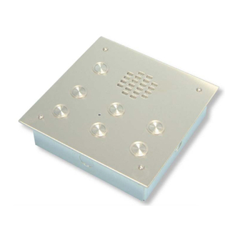
Summary of Contents for Videx 940ST
- Page 2 WIRING DIAGRAM (VR PANEL) PAGE 14 WIRING DIAGRAM (ISOLATION) PAGE 15 WIRING DIAGRAM (3 DOOR) PAGE 16 WIRING DIAGRAM (VIDEO) PAGE 17 TROUBLE SHOOTING GUIDE PAGE 18 VR PANEL LAYOUTS PAGE 19 USER INSTRUCTIONS (925MSL) PAGE 20 USER INSTRUCTIONS (940ST)
- Page 4 Any damage caused to the equipment due to faulty installations where the information in this manual has not been followed is not the responsibility of VIDEX security UK LTD. Description The sentry 1 system can be used as a one or two door audio or video system.
-
Page 5: Operation
Videophones are available with door open button and spare services button. Other options may be available on request. The heart of the system is the sentry 1 control PCB, which has the following features :- 12V DC operation Voltage free contacts for the lock outputs. (Double pole 5A 30VDC) Timed calltone, speak time and lock open time :- CALLTONE LENGTH SPEECH LENGTH... - Page 6 (The link should only be fitted in position B when the system is being tested or being used as a one door system). VIDEX run training courses for engineers who have not installed the sentry 1 system before.
- Page 8 Connections :- + 12 VOLTS SUPPLY VOUT + 12 VOLTS OUT NEGATIVE SUPPLY NEGATIVE SUPPLY BUTTON COMMONS RECEIVE SPEECH (DOOR ONE) TRANSMIT SPEECH (DOOR ONE) SWITCHED + 12 VOLTS, AMP SUPPLY NEGATIVE AMP SUPPLY TRIGGER FROM DOOR ONE ENGAGED OUTPUT (HIGH WHEN ENGAGED) RECEIVE SPEECH (DOOR TWO) TRANSMIT SPEECH (DOOR TWO) SWITCHED + 12 VOLTS, AMP SUPPLY...
- Page 10 4 WAY ISOLATION PCB Description :- • One PCB required for every four handsets. • Isolates the speech, lock and call lines with the use of relays. • protects the +12v supply and door monitoring line with fuses. There are LED's on the isolation PCB to indicate which phone has been •...
-
Page 11: Installation
Installation The wiring diagrams in the manual should be followed carefully. heavy duty conductors on wiring diagrams are shown heavily outlined, These wires should be doubled up. Lock release back EMF protection : A diode must be fitted across the terminals on the lock release to suppress back EMF voltages. -
Page 21: Troubleshooting Guide
TROUBLE SHOOTING GUIDE When trouble shooting a large system, it will be easier to break the system down to a manageable size. The simplest way to do this is to remove all but one handset. Doing this, you can confirm the door panel and control cabinet are free from faults.


Need help?
Do you have a question about the 940ST and is the answer not in the manual?
Questions and answers