Table of Contents
Advertisement
Model No. 831.15962.0
Serial No.
Write the serial number in the
space above for reference.
• Assembly
• Operation
• Maintenance
• Part List and Drawing
Sears, Roebuck and Co.
Hoffman Estates, IL 60179
CAUTION
Read all precautions and instruc-
tions in this manual before using
this equipment. Keep this manual
for future reference.
WEIGHT BENCH EXERCISER
Serial
Number
Decal
User's Manual
Advertisement
Table of Contents

Related Manuals for iFIT WEIDER PRO 8500


Summary of Contents for iFIT WEIDER PRO 8500
- Page 1 Model No. 831.15962.0 Serial No. WEIGHT BENCH EXERCISER Write the serial number in the User’s Manual space above for reference. Serial Number Decal • Assembly • Operation • Maintenance • Part List and Drawing Sears, Roebuck and Co. Hoffman Estates, IL 60179 CAUTION Read all precautions and instruc- tions in this manual before using...
- Page 2 TABLE OF CONTENTS WARNING DECAL PLACEMENT ............. . .2 IMPORTANT PRECAUTIONS .
- Page 3 IMPORTANT PRECAUTIONS WARNING: To reduce the risk of serious injury, read all important precautions and instructions in this manual and all warnings on the weight bench before using the weight bench. Sears assumes no responsibility for personal injury or property damage sustained by or through the use of this product.
- Page 4 17. Always set both spotters, both barbell rests, 21. Always move the bench out of the way when and both barbell spotters at the same height. performing an exercise that does not require the bench. 18. Always place the same amount of weight on both ends of the weight carriage, weight bar, 22.
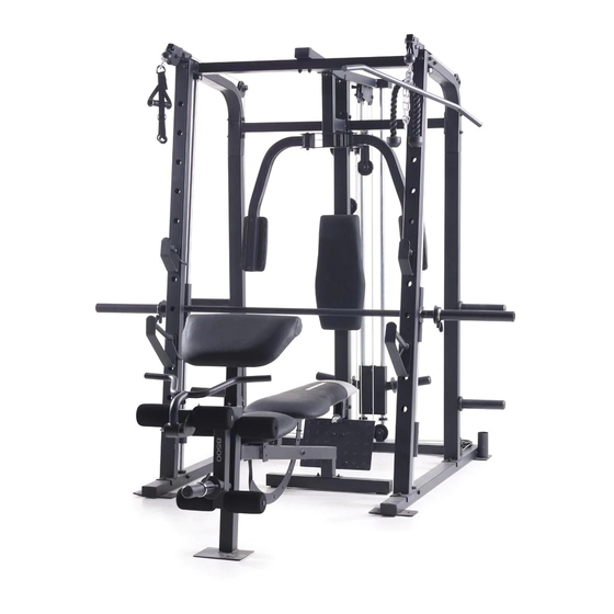
- Page 5 BEFORE YOU BEGIN Thank you for selecting the versatile WEIDER reading this manual, please see the back cover of this ® PRO 8500 weight bench. The PRO 8500 weight manual. To help us assist you, note the product model bench offers a selection of weight stations designed number and serial number before contacting us.
- Page 6 PART IDENTIFICATION CHART Use the drawings below to identify the small parts needed for assembly. The number in parentheses below each drawing is the key number of the part, from the PART LIST near the end of this manual. Note: If a part is not in the hardware kit, check to see whether it has been preassembled.
- Page 7 M10 x 68mm Bolt (90) M10 x 65mm Bolt (105) M6 x 70mm Screw (87) M10 x 65mm Carriage Bolt (83) M8 x 70mm Carriage Bolt (143) M10 x 60mm Bolt (88) M10 x 75mm Bolt (102) M10 x 50mm Bolt (104) M10 x 75mm Hex Bolt (106) M10 x 45mm Bolt (141) M10 x 85mm Bolt (103)
- Page 8 ASSEMBLY • Assembly requires two persons. • In addition to the included tool(s), assembly requires the following tools: • Because of its weight and size, assemble the two adjustable wrenches weight bench in the location where it will be used. Make sure that there is enough clearance to walk one rubber mallet around the weight bench as you assemble it.
- Page 9 2. Attach a Stabilizer Foot (50) to a Base (1) with two M4 x 19mm Screws (82). Next, orient a Base Foot (51) as shown. Attach the Base Foot (51) to the Base (1) with two M4 x 19mm Screws (82). Then, insert four M10 x 65mm Carriage Bolts (83) upward through the Base (1).
- Page 10 4. Attach a Base (1) and a Storage Tube (137) to the Center Base (2) with two M10 x 93mm Bolts (97) and an M10 Locknut (79). Do not tighten the Bolts yet. Attach the other Base (not shown) and the other Storage Tube (not shown) to the Center Base (2) in the same way.
- Page 11 6. Attach the Left Support (6) to the left Base (1) with the indicated two M10 x 65mm Carriage Hole Bolts (83) and two M10 Locknuts (79). Do not tighten the Locknuts yet. Repeat this step with the Right Support (7). 7.
- Page 12 8. Attach an Upright (3) to the left Base (1) with the indicated two M10 x 65mm Carriage Bolts (83) and two M10 Locknuts (79). Do not tighten the Locknuts yet. Repeat this step with the other Upright (not shown). 9.
- Page 13 10. Orient the a Spotter Carriage (24) as shown. Slide the Spotter Carriage (24) and two Carriage Bumpers (27) onto the left Weight Bar Guide (5). Then, engage the Spotter Carriage onto the Left Upright (3). Repeat this step with the other Spotter Carriage (not shown) and the right Weight Bar Guide (not shown).
- Page 14 13. Insert a Guide Cap (33) upward into a Side Top Frame (13). Set the Side Top Frame on the left Weight Bar Guide (5) and insert it into the Left Support (6). Attach the Side Top Frame (13) to the left Upright (3) and the Left Support (6) with two M10 x 75mm Bolts (102), two M10 x 25mm Screws (98), four M10 Split Washers (93), and...
- Page 15 16. Attach a Support Frame (15) to the left Side Top Frame (13) with two M10 x 93mm Bolts (97), two M10 Washers (84), and two M10 Locknuts (79). Do not tighten the Locknuts yet. Attach the other Support Frame (15) to the right Side Top Frame (13) in the same way.
- Page 16 19. Attach the Top Frame (16) to the Center Top Frame (14) with two M10 x 115mm Bolts (101), four M10 Washers (84), and two M10 Locknuts (79). Do not tighten the Locknuts yet. 20. Attach the Top Frame (16) to the Carriage Guides (64) with two M10 x 90mm Bolts (89), four M10 Washers (84), four 25mm Spacers (55), and two M10 Locknuts (79).
- Page 17 22. Attach the Foot Plate (9) to the Center Base (2) and the Backrest Upright (8) with four M10 x 20mm Bolts (77) and four M10 Locknuts (79). See steps 4–9, 13, 15–17, and 19–21. Tighten all of the Bolts, Screws, and Locknuts used in these steps.
- Page 18 25. Route the Butterfly Cable (71) under a 90mm Pulley (58). Attach the 90mm Pulley to the Short Double U-bracket (46) with an M10 x 43mm Bolt (96) and an M10 Locknut (79). 26. Route the Butterfly Cable (71) over a V-pulley (60).
- Page 19 28. Identify the Low Cable (72). Slide a Cable Stop (52) onto the Low Cable (72). Hold an M6 Locknut (100) inside a Clip (53), and insert the Low Cable (72) into the Clip and the Locknut. Next, hold the crimp on the Low Cable with pliers, and insert a screwdriver between the Clip and the Locknut.
- Page 20 31. Wrap the Low Cable (72) over a 90mm Pulley (58). Attach the 90mm Pulley to the Top Frame (16) with an M10 x 43mm Bolt (96) and an M10 Locknut (79). 32. Route the Low Cable (72) under a 90mm Pulley (58).
- Page 21 34. Attach the Low Cable (72) inside the Weight Carriage (41) with an M10 x 68mm Bolt (90), two M10 Washers (84), two 24mm Spacers (45), and an M10 Locknut (79). Attach the lower Carriage Bushing (42) inside the Weight Carriage (41) with an M10 x 68mm Bolt (90), two M10 Washers (84), a 50mm Spacer (44), and an M10 Locknut (79).
- Page 22 36. Route the High Cable (54) over a 90mm Pulley (58). Attach the 90mm Pulley and a Plastic Cable Trap (63) to the left Side Top Frame (13) with an M10 x 50mm Bolt (104) and an M10 Locknut (79). Make sure that the Plastic Cable Trap is oriented to hold the High Cable in the groove of the 90mm Pulley.
- Page 23 39. Route the High Cable (54) under a 90mm Pulley (58). Attach the 90mm Pulley to the Center Base (2) with an M10 x 43mm Bolt (96) and an M10 Locknut (79). 40. Route the High Cable (54) over a 90mm Pulley (58).
- Page 24 42. Route the High Cable (54) around a 115mm Pulley (59). Attach the 115mm Pulley, a Long Metal Cable Trap (62), and an M10 Washer (84) to the Center Base (2) with an M10 x 75mm Bolt (102) and an M10 Locknut (79). Make sure that the Long Metal Cable Trap is oriented to hold the High Cable in the groove of the 115mm Pulley.
- Page 25 45. Route the High Cable (54) through the right Upright (3) and a Swivel Arm (32). Make sure that the High Cable is routed on the indicated side of the small rod on the Swivel Arm. Then, route the High Cable (54) over a 90mm Pulley (58).
- Page 26 47. Attach an Arm Pad (30) to the Right Arm (11) with two M6 x 70mm Screws (87) and two M6 Washers (86). Attach the other Arm Pad (30) to the Left Arm (10) in the same way. 48. Insert the Left Barbell Rest (35) and the Left Barbell Spotter (36) into the Left Upright (3).
- Page 27 50. Attach two Stabilizer Feet (50) to the Bench Stabilizer (108) with four M4 x 19mm Screws (82). 51. Attach the Bench Stabilizer (108) to the Bench Frame (107) with two M8 x 70mm Carriage Bolts (143) and two M8 Locknuts (78). Do not tighten the Locknuts yet.
- Page 28 54. Orient the two Backrest Frames (118) so that the indicated holes are nearer the bottom. Holes Attach the Backrest Frames (118) to the Backrest Bracket (111) with four M8 x 42mm Bolts (130), four M8 Washers (94), and four M8 Locknuts (78).
- Page 29 57. Attach the tether on the Seat Pin (123) to the Seat Frame (122) with an M4 x 19mm Screw (82). 58. Pull the Bench Knob (124) outward and insert the Backrest Bracket (111) through the Bench Frame (107). Engage the Bench Knob into the Backrest Bracket.
- Page 30 60. Insert the Seat Pin (123) into the Seat Frame (122) and the Bench Frame (107). See step 54 Tighten the M8 Locknuts (78). See step 55. Tighten the M6 x 40mm Screws (39). 61. Insert the Long Pad Tube (115) through the Front Leg (109).
- Page 31 63. Attach the Curl Bumper (133) to the Curl Bar (112) with an M4 x 19mm Screw (82). Attach the Curl Bar (112) the Leg Lever (110) with the Curl Pin (142). 64. Attach the Curl Pad (114) to the Curl Post (113) with two M8 x 20mm Screws (34).
- Page 32 65. Remove the 57mm x 1.5mm Square Cap (131) from the Front Leg (109). Insert the Curl Post (113) into the Front Leg (109) and secure the Curl Post with the Curl Post Knob (136). Fully tighten the Curl Post Knob. 66.
- Page 33 ADJUSTMENT This section explains how to adjust the weight bench. See the EXERCISE GUIDELINES on page 38 for impor- tant information about how to get the most benefi t from your exercise program. Also, refer to the accompanying exercise guide to see the correct form for several exercises. ATTACHING ACCESSORIES To use a Handle (67), attach the Handle to the Clip (53) on the end of any cable.
- Page 34 USING THE WEIGHT BAR To use the Weight Bar (17), fi rst place the desired amount of weight (not included) onto the ends of the Weight Bar (see ADDING WEIGHT below). Then, disengage the Locking Bar (18) by rotating it off the Uprights (3).
- Page 35 ADJUSTING THE SEAT Hold the Seat (116) with one hand and disengage the Seat Pin (123) from the Seat Frame (122). Move the Seat to the desired position and reengage the Seat Pin into the Seat Frame and the Bench Frame (107).
- Page 36 CABLE DIAGRAM The diagram below shows the correct route of each cable. The numbers in each drawing show the correct route of that cable. Use the diagram to make sure that each cable is correctly routed. If a cable is not correctly routed, the weight bench will not function properly and damage may occur.
- Page 37 MAINTENANCE Make sure that all parts are properly tightened each time you use the weight bench. Replace any worn parts immediately. Clean the weight bench with a damp cloth and mild, non-abrasive detergent; do not use solvents. TIGHTENING THE CABLES Woven cable, the type of cable used on the weight bench, can stretch slightly when it is fi...
- Page 38 EXERCISE GUIDELINES FOUR TYPES OF STRENGTH WORKOUTS to determine the appropriate length of time for each workout, and the numbers of repetitions and sets to Note: A “repetition” is one complete cycle of an complete. Progress at your own pace and be sensitive exercise, such as one sit-up.
- Page 39 PART LIST Model No. 831.15962.0 R1115A Key No. Qty. Description Key No. Qty. Description Base Base Foot Center Base Cable Stop Upright Clip Right Barbell Rest High Cable Weight Bar Guide 25mm Spacer Left Support Swivel Bushing Right Support Swivel Cap Backrest Upright 90mm Pulley Foot Plate...
- Page 40 Key No. Qty. Description Key No. Qty. Description M10 x 115mm Bolt Curl Bushing M10 x 75mm Bolt 25mm x 1.5mm Round Cap M10 x 85mm Bolt 19mm Round Cap M10 x 50mm Bolt Foam Pad M10 x 65mm Bolt Short Pad Tube M10 x 75mm Hex Bolt M8 x 42mm Bolt...
- Page 41 EXPLODED DRAWING A Model No. 831.15962.0 R1115A...
- Page 42 EXPLODED DRAWING B Model No. 831.15962.0 R1115A 84 84...
- Page 43 EXPLODED DRAWING C Model No. 831.15962.0 R1115A 84 93...
- Page 44 90 DAY FULL WARRANTY If this Sears Weight Bench Exerciser fails due to a defect in material or workmanship within 90 days of the date of purchase, call 1-800-4-MY-HOME (1-800-469-4663) to arrange for free repair (or ® replacement if repair proves impossible). This warranty does not apply when the Weight Bench Exerciser is used commercially or for rental pur- poses.
Need help?
Do you have a question about the WEIDER PRO 8500 and is the answer not in the manual?
Questions and answers