
Related Manuals for Sharp V-1


Summary of Contents for Sharp V-1
- Page 1 VERTICAL MILL GENERAL & ELECTRICS MANUAL Manual Number KRDM24C0 Date NOV,2018 REV V4.0S...
- Page 2 SHARP V-1 KNEE MILL GENERAL MANUAL IMPORTANT SAFETY NOTICE WARNING The following documentations are provided by us. (1) Introduction manual (2) Electrical document (3) Other document provided by OEM partners WARNING !!! Please read these documentations thoroughly before using the machine. An adequate training by the manufacturer or by OEM is required before starting to use these machines.
- Page 3 SHARP V-1 KNEE MILL GENERAL MANUAL SPECIFICATION MODEL Working area 1473 × 305 mm Working table No.of T slots 15.9 mm 3 off Longitudinal travel- 1016 mm (Standard) X axis (with DRO system) 400 mm (Standard) Cross travel-Y axis (with DRO system)
- Page 4 SHARP V-1 KNEE MILL GENERAL MANUAL STANDARD ACCESSORIES Ł American red turcite on X and Y axes. Ł Dovetail slideways on X axis. Ł Square slideways on Y axes. Ł Square slideways on Z axis. Ł Hardened and ground X, Y, Z axes .
- Page 5 SHARP V-1 KNEE MILL GENERAL MANUAL DIMENSION (STANDARD) 1480 2290 1720 1473 UNIT : mm KRDM24C0 V4.0S...
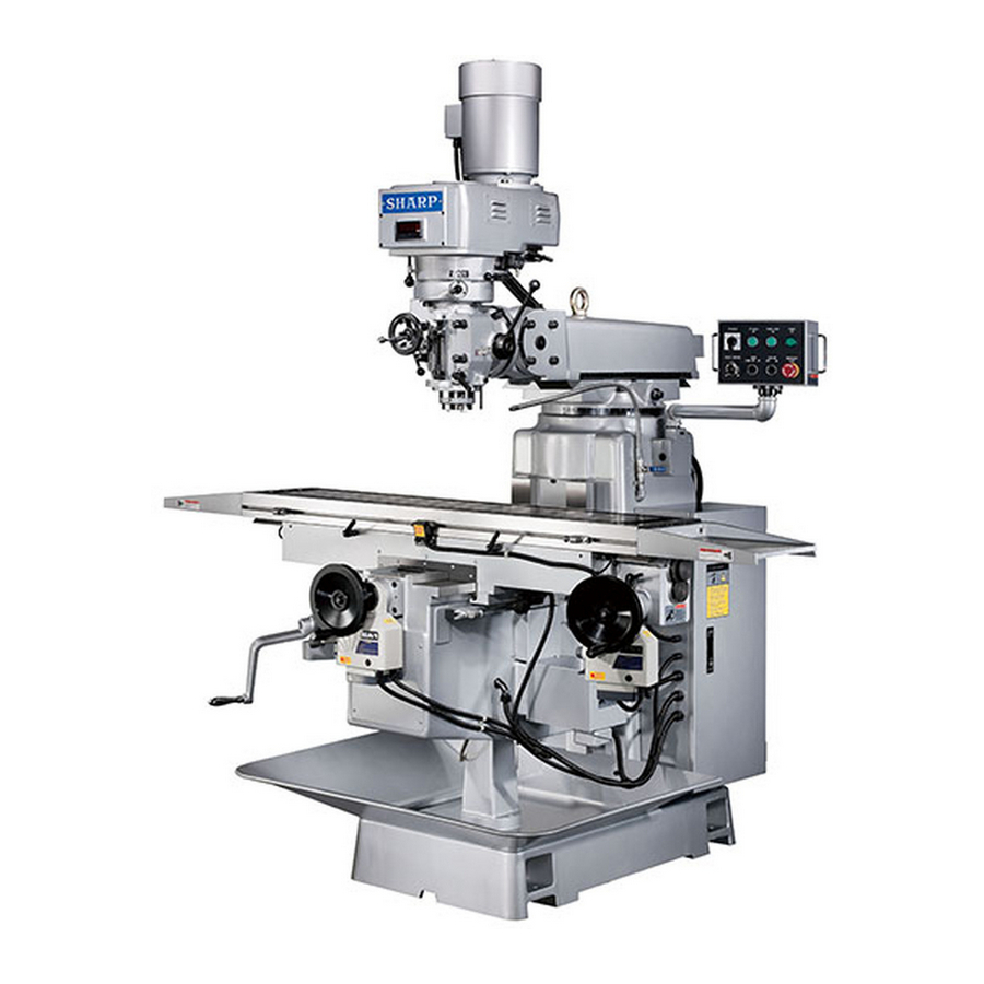
- Page 6 SHARP V-1 KNEE MILL GENERAL MANUAL KRDM24C0 V4.0S...
-
Page 7: Table Of Contents
SHARP V-1 KNEE MILL GENERAL MANUAL CONTENTS CHAPTER 1 HEALTH AND SAFETY OPERATOR SAFETY ..................CH1-2 HEALTH AND SAFETY AT WORK ..............CH1-2 NOISE LEVEL ....................CH1-3 OPERATING HAZARDS ................... CH1-3 VARIABLE SPEED DRIVE ................CH1-4 POTENTIAL DANGER AREAS ................. CH1-4 OPERATING SAFETY PRECAUTIONS ............ - Page 8 SHARP V-1 KNEE MILL GENERAL MANUAL CHAPTER 3 INSTALLATION PREPARATION ....................CH3-2 INSTALLATION LOCATION ................CH3-4 FOUNDATION CONSTRUCTION PLAN ............CH3-5 ELECTRICAL REQUIREMENT ................. CH3-7 LEVELING THE MACHINE ................CH3-12 INSPECTION ..................... CH3-14 CHAPTER 4 & 5 OPERATIONAL PROCEDURE & MECHANISM MACHINE ......................
- Page 9 SHARP V-1 KNEE MILL GENERAL MANUAL CHAPTER 6 ADJUSTMENT MECHANICAL ADJUSTMENT ................CH6-2 ADJUSTMENT OF TABLE GIB ................. CH6-3 ADJUSTMENT OF SADDLE GIB ..............CH6-3 ADJUSTMENT OF HEADSTOCK GIB .............. CH6-4 ADJUSTMENT OF BACKLASH ................ CH6-5 CHAPTER 7 MACHINE MAINTENANCE PREPARATION BEFORE MAINTENANCE ............
- Page 10 SHARP V-1 KNEE MILL GENERAL MANUAL CHAPTER 8 APPENDIX TROUBLE SHOOTING ..................CH8-2 ISO METRIC THREAD DATA ................CH8-6 CUTTING SPEED ....................CH8-6 CUTTING DEPTH ....................CH8-8 FEED SPEED ....................CH8-8 CHAPTER 9 PARTS LIST HEAD DRAWING ....................H01-1 VERTICAL MILLING HEAD DRAWING ............H02-1 UP-DOWN &...
- Page 11 SHARP V-1 KNEE MILL GENERAL MANUAL This page is intentionally left blank. KRDM24C0 V4.0S...
-
Page 12: Chapter 1 Health And Safety
SHARP V-1 KNEE MILL GENERAL MANUAL CHAPTER 1 HEALTH AND SAFETY PLEASE READ CAREFULLY BEFORE OPERATION OF YOUR MACHINE CH1-1 KRDM24C0 V4.0S... -
Page 13: Operator Safety
SHARP V-1 KNEE MILL GENERAL MANUAL 1.1 OPERATOR SAFETY Safety devices are installed in this machine to protect the operator from in injury. However, this machine is fast, powerful machine can be dangerous if used under improper circumstances. Please read the following health and safety guidance notes and understand how to operate the machine before using the machine. -
Page 14: Noise Level
SHARP V-1 KNEE MILL GENERAL MANUAL 1.3 NOISE LEVEL The noise level of this machine is within 80dB(A). In real life, the noise level can be higher than 80dB(A) because actual working conditions might be different. WARNING !!! Do not stay in the working area with an unpleasant noise level without wearing appropriate protective equipment, such as the earplug. -
Page 15: Variable Speed Drive
SHARP V-1 KNEE MILL GENERAL MANUAL 1.5 VARIABLE SPEED DRIVE Note that these machines are designed to allow fast and easy change of the spindle speed. Take care to ensure that the workpiece is secure and the maximum safe speed for any operation are not exceeded. -
Page 16: Operating Safety Precautions
SHARP V-1 KNEE MILL GENERAL MANUAL 1.7 OPERATING SAFETY PRECAUTIONS Never use the machine without adequate lighting or if the machine light is broken. The floor could become slippery because of the spilt water or oil and cause accident. Ensure the floor is clean, dry and orderly. -
Page 17: General Principles Concerning Operator Safety For This Machine
SHARP V-1 KNEE MILL GENERAL MANUAL 1.8 GENERAL PRINCIPLES CONCERNING OPERATOR SAFETY FOR THE MACHINE Do not wear rings, watches, ties or loose sleeved clothing. Always use the recommended or equivalent hydraulic oil, lubricant oil and grease. The working table adjacent to the machine should be secured to prevent the workpiece room falling onto the machine. - Page 18 SHARP V-1 KNEE MILL GENERAL MANUAL 16. Beware of irregular shaped workpieces. 17. Beware of large burrs on workpieces. 18. Always select the correct tool for the job. 19. Do not run the machine unattended. 20. Do not use tools without handles.
- Page 19 SHARP V-1 KNEE MILL GENERAL MANUAL 35. Beware of performing another operation while in close proximity to the rotating parts of the machine. 36. Be sure spindle is not running when using gauges on the machine. 37. Always wear protection before operating the machine.
- Page 20 SHARP V-1 KNEE MILL GENERAL MANUAL 53. Always use the correct equipment. 54. Never take cuts beyond the machine’s capability. 55. Never use excessive forces in polishing, filing. 57. Always use the proper hand tool to remove swarf. (a) Never hurry to remove swarf.
-
Page 21: Signs
SHARP V-1 KNEE MILL GENERAL MANUAL 1.9 SIGNS (11) (12) (13) CH1-10 KRDM24C0 V4.0S... - Page 22 SHARP V-1 KNEE MILL GENERAL MANUAL 1.9.1 MACHINE SIGNS (1)-1 (1)-2 (1)-3 Spindle air brake (3) S-A1230 Speed selection change caution (4) S-A1210 Speed selection CH1-11 KRDM24C0 V4.0S...
- Page 23 SHARP V-1 KNEE MILL GENERAL MANUAL Engage power feed warning Lubrication added (7) S-S2081 EYE Protection Warning (8) S-S1060 Hit head warning (9) -1 S-S1101 AC220V Yellow Sticker (9) -4 S-S1105 AC440V Yellow Sticker (10) CH1-12 KRDM24C0 V4.0S...
- Page 24 SHARP V-1 KNEE MILL GENERAL MANUAL (11) S-S1110 Lightning Mark-S (12) S-S1123 ISO 68 (13) S-S1071 Safety Warning NOTE!!! On the MILL machine there are shipping brackets the hold the machine head, ATC and axes in place during shipping. These brackets must be removed before operating the machine.
- Page 25 SHARP V-1 KNEE MILL GENERAL MANUAL This page is intentionally left blank CH1-14 KRDM24C0 V4.0S...
-
Page 26: Chapter 2 Shipping And Handling
SHARP V-1 KNEE MILL GENERAL MANUAL CHAPTER 2 SHIPPING AND HANDLING PLEASE READ CAREFULLY BEFORE SHIPPING AND HANDLING OF THIS MACHINE CH2-1 KRDM24C0 V4.0S... -
Page 27: Shipping And Handling
SHARP V-1 KNEE MILL GENERAL MANUAL 2.1 SHIPPING AND HANDLING This mill is composed of bed base, variable speed head or, saddle working table, operation panel, hydraulic system, lubrication system and electrical cabinet. The shipping and handling equipment used should be able to lift a gross weight of 4 tons at least. - Page 28 SHARP V-1 KNEE MILL GENERAL MANUAL 2.1.3 NOTICES Check if there is any people or blockage around the working area before starting to lift the package. Blockage should be removed and people be told to leave before proceed. Do not stop the lifting motions suddenly during the process. Prevent sudden movement of the machine, too quick and the machine could become unbalanced.
-
Page 29: Lifting With The Machine Packed
SHARP V-1 KNEE MILL GENERAL MANUAL 2.2 LIFTING WITH THE MACHINE PACKED 2.2.1 SAFETY RULES FOR MACHINE LIFTING The following safety rules must be absolutely followed when lifting and/or moving the machine Ensure all the parts of the machine are fully secured before lifting or moving it. - Page 30 For V-1 machine, the loading capacity of the lifting equipment should be 4 tons at least. For V-1 machine,if 2 machine package in one pallet, the loading capacity of the lifting equipment should be 7 tons at least. Beware that the lifting truck might overturne because of an improper lifting height.
- Page 31 SHARP V-1 KNEE MILL GENERAL MANUAL 2.2.3 SING CRANE OR OTHER LIFTING EQUIPMENT Wire cables and chains of the lifting equipment should be able to bear a load of 4 tons at least. The loading capacity below 4 tons is prohibited.
-
Page 32: Fix Machine During Transportation
SHARP V-1 KNEE MILL GENERAL MANUAL 2.3 FIX MACHINE DURING TRANSPORTATION Ensure to fasten all the loosen parts firmly inside the crate before transportation. 2.4 REMOVE FIXTURE Ensure to remove all the fixtures listed below before operating the machine Remove the wooden block under the headstock. - Page 33 SHARP V-1 KNEE MILL GENERAL MANUAL 2.5.2 STORAGE OF THE BARE MACHINE Ensure to fasten all the loose parts and have an anti-rust treatment of the machine. Ensure to fasten all the sliding guards and doors to prevent from moving even falling.
-
Page 34: Chapter 3 Installation
SHARP V-1 KNEE MILL GENERAL MANUAL CHAPTER 3 INSTALLATION PLEASE READ CAREFULLY BEFORE INSTALLATION THIS MACHINE CH3-1 KRDM24C0 V4.0S... -
Page 35: Preparation
SHARP V-1 KNEE MILL GENERAL MANUAL 3.1 PREPARATION Ensure the site space and the path width is large enough to install and transport the whole machine at least 30 working days before the arrival of this machine. If short of space, please inform local agent or us as soon as possible, we will provide a suggestion and information service for you. - Page 36 SHARP V-1 KNEE MILL GENERAL MANUAL 3.1.1 SPACE REQUIREMENT A distance of at least 500 mm is required from machine to wall end objects or between machines to ensure easy repair, cleaning and maintenance of machine. Recommended site space for the machine with standard equipment: CH3-3 KRDM24C0 V4.0S...
-
Page 37: Installation Location
SHARP V-1 KNEE MILL GENERAL MANUAL 3.2 INSTALLATION LOCATION To upgrade the operation efficiency and accuracy of this machine, a proper foundation is required. It is recommended that this machine should be located in a plant with ambient temperature of around 20 °C, and without the influence of dampness, chemical gas or trembling. -
Page 38: Foundation Construction Plan
SHARP V-1 KNEE MILL GENERAL MANUAL 11. Do not place this machine near any equipment causing electronic noise. 12. Electrical equipment shall withstand the effects of transportation and storage temperature within a range of -25° C to 55° C and for short periods not exceeding 24 hours at up to + 70°C. - Page 39 SHARP V-1 KNEE MILL GENERAL MANUAL 3.3.2 FOUNDATION CONSTRUCTION PLAN TWO Ensure the ground is rigid enough to place the machine. Place the leveling blocks on the ground, then place the machine upon the leveling blocks. Level the machine accordingly.
-
Page 40: Electrical Requirement
SHARP V-1 KNEE MILL GENERAL MANUAL 3.4 ELECTRICAL REQUIREMENT This machine should be installed under the right electrical environments. WARNING!!! Before connecting the power wires, make sure the voltage is the same for both the machine and the plant power. - Page 41 SHARP V-1 KNEE MILL GENERAL MANUAL 3.4.2 POWER WIRING Follow the instructions below to wire power Ensure the electrical cables have the same or better power rating as prescribed in the electrical document. Only qualified engineers are allowed to connect the power cable of this machine.
- Page 42 SHARP V-1 KNEE MILL GENERAL MANUAL 3.4.3 GROUNDING Connect the connector marked with “PE” inside the electric cabinet to the external grounding conductor. If it is no “PE” wiring on the external power supply system, please prepare one ground wire and set a grounding copper rod under the ground, then connect the “PE”...
- Page 43 SHARP V-1 KNEE MILL GENERAL MANUAL 3.4.4 ELECTRICAL CONNECTION CH3-10 KRDM24C0 V4.0S...
- Page 44 SHARP V-1 KNEE MILL GENERAL MANUAL 3.4.5 SPECIFICATION OF ELECTRICAL REQUIREMENT 220V Current-fault Machine Rated Capacity Wire breaker 8.0 m D 33 A 40 A 440V Current-fault Machine Rated Capacity Wire breaker 19 A 5.5 m D 20 A WARNING !!! Ensure the electrical cables have the same or better power rating as prescribed in the electrical document.
-
Page 45: Leveling The Machine
SHARP V-1 KNEE MILL GENERAL MANUAL 3.5 LEVELING THE MACHINE 3.5.1 ADJUST THE MACHINE Place the temporary foundation pads or leveling blocks on the foundation. In the first case, insert the L-shape fixing stud through the pad and foundation bolt, then fasten the fixing stud with the nut. - Page 46 SHARP V-1 KNEE MILL GENERAL MANUAL 3.5.2 ALIGNMENT OF HEAD In order to get precision when machining, the head of machine perfectly square with table is necessary. Use gauge to check the square within 0.02mm. Please check square of machine following instructions: Loosen the binding bolts.(see the figure)
-
Page 47: Inspection
SHARP V-1 KNEE MILL GENERAL MANUAL 3.6 INSPECTION 3.6.1 BEFORE POWER START-UP Ensure the power supply specification is correct. Ensure electric cables and connectors are appropriating based on the local safety regulations. Ensure connections between the machine and grounding terminals are correct. - Page 48 SHARP V-1 KNEE MILL GENERAL MANUAL 3.6.2 AFTER POWER START-UP Make sure the power source wires are connected to the right connection points. Follow the instructions below to check the power wiring. Ensure functions of the power supply switches are normal.
- Page 49 SHARP V-1 KNEE MILL GENERAL MANUAL This page is intentionally left blank CH3-16 KRDM24C0 V4.0S...
-
Page 50: Chapter 4 & 5 Operational Procedure
SHARP V-1 KNEE MILL GENERAL MANUAL CHAPTER 4 & 5 OPERATIONAL PROCEDURE & MECHANISM PLEASE READ CAREFULLY BEFORE STARTING TO OPERATE AND ADJUSTMENT THIS MACHINE CH4-1 KRDM24C0 V4.0S... -
Page 51: Machine
SHARP V-1 KNEE MILL GENERAL MANUAL 4.1 MACHINE This machine could be only operated under manual or automatic mode( wihh control ). The information about how to operate this machine is given below. Please read carefully before starting to operate this machine. - Page 52 SHARP V-1 KNEE MILL GENERAL MANUAL Check the coolant level of the cutting water tank regularly. Fill it up if necessary. Always wear the correct protection outfit, such as safety goggles, oil-proof safety shoes, safety uniform, etc. before starting the machine.
-
Page 53: Start And Stop The Machine
SHARP V-1 KNEE MILL GENERAL MANUAL 4.4 START AND STOP THE MACHINE 4.4.1 START PROCEDURE Connect the power supply. To turn on the main power, the procedures below must be following: Turn on the factory’s main power supply ( Switch... -
Page 54: Preparation
SHARP V-1 KNEE MILL GENERAL MANUAL 4.5 PREPARATION 4.5.1 WARNINGS Always use the recommended cutting tools. Otherwise this might cause an accident. Do not use broken or defective cutting tools. Ensure to have a sound lighting facility around the working area. -
Page 55: Operation
SHARP V-1 KNEE MILL GENERAL MANUAL 4.6 OPERATION 4.6.1 WARNINGS Beware of loose or long hair near the working area to avoid unnecessary accident from happening. Do not wear gloves when operating the machine, otherwise it will cause dangers. Always handle large work pieces with appropriate manpower. - Page 56 SHARP V-1 KNEE MILL GENERAL MANUAL 4.6.2 MAIN PARTS Bed base Turret Spindle motor Variable head Spindle Saddle Knee Table 10. Control panel CH4-7 KRDM24C0 V4.0S...
- Page 57 SHARP V-1 KNEE MILL GENERAL MANUAL 4.6.3 SWIVEL TURRET To swivel turret, the procedures below must be following: Use spanner to unlock the 4 bolts. Swivel the turret to the required location that you need an Lock the 4 bolts.
- Page 58 SHARP V-1 KNEE MILL GENERAL MANUAL 4.6.5 CLAMPING TABLE Ifoperator don’t use longitudinal table feed, it can be clamped to add rigidity. This can decrease vibration when doing heavy cut. The clamping table locking lever is located on the front of saddle. Ensure to use asequately clamping pressure to set it, otherwise excessive pressure will broke the clamping parts.
- Page 59 SHARP V-1 KNEE MILL GENERAL MANUAL 4.6.7 CLAMPING KNEE If operator don' t use knee feed, it can be clamped to add rigidity. This can decrease vibration when doing heavy cut. The clamping lnee locking lever is located on the left side of knee.
- Page 60 SHARP V-1 KNEE MILL GENERAL MANUAL 4.6.8 SAFETY RULE OF POWER FEED ( OPTIONAL ) The power feed equipment is powerful and fast, please uses this equipment carefully. Before using these power feed, please read the operation manual first. Do not try to use this equipment unless you understand how to operate and stop it.
- Page 61 SHARP V-1 KNEE MILL GENERAL MANUAL 4.6.9 CONTROL PANEL 4.6.9.1 CONTROL PANEL (WITH INVERTER HEAD) SPINDLE REV / FWD SWITCH SPINDLE ON BUTTON POWER FEED ON BUTTON POWER ON LAMP SPINDLE OVERRIDE SWITCH KNEE UP / DOWN SWITCH COOLANT ON / OFF SWITCH...
- Page 62 SHARP V-1 KNEE MILL GENERAL MANUAL 4.6.10 VARIABLE SPEED HEAD Handlwheel for manual feed of quill Adjustable micrometer depth stop Indicator mounting rod Spindle brake Quill feed speed selector lever Quill feed reversing knob Quill feed clutch control lever Quill 10.
- Page 63 SHARP V-1 KNEE MILL GENERAL MANUAL 4.6.11 CHANGE HIGH / LOW SPEED RANGE There are 3-speed range, low-speed range, high-speed range and neutral.(see below range list). To change the speed range, the procedures below must be following: Ensure the spindle is full stop ( Move speed range select lever 12 to change the speed range ( rotate the spindle by hand until the clutch engages fully.
- Page 64 SHARP V-1 KNEE MILL GENERAL MANUAL 4.6.12 CHANGE SPINDLE SPEED Start the spindle and turn the spindle override button to change the spindle speed. WARNING !!! Do not change the spindle speed when the spindle is stationary. 4.6.13 SPINDLE BRAKE Move the spindle brake lever 5 front or back can stop spindle.
- Page 65 SHARP V-1 KNEE MILL GENERAL MANUAL 4.6.14 AUTOMATIC QUILL FEED There are 6 parts ( NO. 6 , 7 , 8 , 13 , 15 , 16 ) necessary to adjust when use automatic quill feed. To use automatic quill feed, the procedures below must be following: Ensure the spindle is full stop and the quill lock“16”is off...
- Page 66 SHARP V-1 KNEE MILL GENERAL MANUAL 4.6.16 HAND QUILL FEED TWO To operate feed by quill feed handle, the procedures below must be following: Ensure the spindle is full stop and the quill lock 16 is off ( use the micrometer dial 15...
-
Page 67: Break-Up
SHARP V-1 KNEE MILL GENERAL MANUAL 4.6.18 LOCK QUILL If operators don’t use quill feed, he can use the quill lock lever 16 to clamp the quill. It is necessary to be clamped when operators do cutting. Ensure to use adequately clamping pressure to set it, otherwise excessive pressure will broke the clamping parts. - Page 68 SHARP V-1 KNEE MILL GENERAL MANUAL 4.9.1 NOTICES Ensure to turn off the power supply of the machine and put “Under Maintenance. Do not turn on the power supply” warning signs on visible spots before cleaning the machine or accessories. Ensure the machine is fully stopped before maintaining the machine.
-
Page 69: Lubricator
SHARP V-1 KNEE MILL GENERAL MANUAL 4.10 LUBRICATOR 4.10.1 PARTS OF LUBRICATOR Electrical control box cover Alarm beeper YET-D1 control box 10. Pressure gauge Oil tank cap 11. One-way elbow adapter Upper lid 12. Lifting rod Inlet filter 13. Shaft set Oil tank 14. - Page 70 SHARP V-1 KNEE MILL GENERAL MANUAL 4.10.2 LABEL Name Plate Danger Outside of the electrical control box top Front side of the electrical control box cover Wiring Diageam Operation Notice Inside of the electrical control box Time Index Table Inside of the electrical control box top cover...
- Page 71 SHARP V-1 KNEE MILL GENERAL MANUAL 4.10.3 LUBRICANT FILLING Remove the oil tank cap and fill the tank with clean lubricant at the level of 80% of the tank height (Fig. 3). Approved lubricant viscosity range is 30~150 cSt. NOTE !!! Viscosity higher than 150 cSt may result the burn down of the lubrication systems.
- Page 72 SHARP V-1 KNEE MILL GENERAL MANUAL Characteristics of Electrical Appliances (a) Loading Capacity Loading the 110% Listed Electrical Current (i.e. 2.2 A) for flowing, and it' s available to let current keep on following without any melting. (b) Temperature Proceed the preceding test for 1.5 hours, keep testing it with the original current every 10 minutes.
- Page 73 SHARP V-1 KNEE MILL GENERAL MANUAL 4.10.4.3 EXTRA FUSE FOR SPARE PARTS One extra fuse for spare parts is attached inside the electrical control box. 4.10.5 LUBRICATOR MAINTENANCE iSHAN centralized lubrication systems are of low maintenance. However, related connection needs to be reviewed if properly fitted to secure the proper function of the system.
-
Page 74: Chapter 6 Adjustment
SHARP V-1 KNEE MILL GENERAL MANUAL CHAPTER 6 ADJUSTMENT PLEASE READ CAREFULLY BEFORE ADJUSTMENT OF THIS MACHINE CH6-1 KRDM24C0 V4.0S... -
Page 75: Mechanical Adjustment
SHARP V-1 KNEE MILL GENERAL MANUAL 6.1 MECHANICAL ADJUSTMENT Ensure to turn off the main power supply and put warning signs on visible spots before inspecting the belt tension. Do not touch or reach over the pulleys and the belts if the power is still on. -
Page 76: Adjustment Of Table Gib
SHARP V-1 KNEE MILL GENERAL MANUAL 6.2 ADJUSTMENT OF TABLE GIB The taper gib “ A” is used for adjusting precision of table moving. The screw “ B ” is used for setting the gib. When adjust the gib, turn the screw counterclockwise to loose the gib a littile, then turn the screw clockwise to adjust the gib until the table move smooth and precisely. -
Page 77: Adjustment Of Headstock Gib
SHARP V-1 KNEE MILL GENERAL MANUAL 6.4 ADJUSTMENT OF HEADSTOCK GIB The taper gib “ A” is used for adjusting precision of knee moving. The screw “ B ” is used for setting the gib. When adjust the gib, turn the screw counterclockwise to loose the gib a little, then turn the screw clockwise to adjust the gib until the knee move smooth and precisely. -
Page 78: Adjustment Of Backlash
SHARP V-1 KNEE MILL GENERAL MANUAL 6.5 ADJUSTMENT OF BACKLASH To adjust backlash, the procedures below must be following: Move the table or saddle to middle position. Withdraw handwheel C and 3 screw Move table or saddle to the location that you can see screws A . - Page 79 SHARP V-1 KNEE MILL GENERAL MANUAL This page is intentionally left blank. CH6-6 KRDM24C0 V4.0S...
-
Page 80: Chapter 7 Machine Maintenance
SHARP V-1 KNEE MILL GENERAL MANUAL CHAPTER 7 MACHINE MAINTENANCE PLEASE READ CAREFULLY BEFORE MAINTENANCE ON THIS MACHINE CH7-1 KRDM24C0 V4.0S... -
Page 81: Preparation Before Maintenance
SHARP V-1 KNEE MILL GENERAL MANUAL 7.1 PREPARATION BEFORE MAINTENANCE Ensure to turn off the main power supply and put under maintenance warning signs on visible spots before maintenance the machine. 7.1.1 NOTICES Fully Understand all the safety instructions illustrated in the manual. - Page 82 SHARP V-1 KNEE MILL GENERAL MANUAL 7.2.1 LUBRICATION OF VARIABLE SPEED HEAD Please lubricate the parts of head following the directions. THE GUIDE TABLE LUBRICANT LUBRICANT FREQUENCY QUANTITY POSITION CHARACTERISTIC HI-LOW speed gear Grease Every month Suitable amount mechanism Light oil...
-
Page 83: Lubrication
SHARP V-1 KNEE MILL GENERAL MANUAL 7.3 LUBRICATION 7.3.1 THE OIL GUIDE TABLE (V2.7) 7.3.1.1 OIL GUIDE TABLE A (For all machine type) Lubrication Tank Lubricant Position Cutting Coolant Slideway and Ballscrew Viscosity ISO VG68 Good Heat Lubricant ŁAnti-wear, conduction ŁGood lubricant... - Page 84 SHARP V-1 KNEE MILL GENERAL MANUAL 7.3.1.2 OIL GUIDE TABLE D (FOR MILLS ) Tool Release Lubricant Position Drawbar Viscosity ISO VG32 ŁAnti-rust, Lubricant Characteristic anti-oxidation ŁGood Stability Lubrication Method Centralized Lub Once Weekly Replace& add Period As needed Tank Capacity...
-
Page 85: Oil System
SHARP V-1 KNEE MILL GENERAL MANUAL 7.4 OIL SYSTEM 7.4.1 V-1 OIL SYSTEM UP-DOWN OIL SYSTEM CH7-6 KRDM24C0 V4.0S... - Page 86 SHARP V-1 KNEE MILL GENERAL MANUAL SADDLE OIL SYSTEM CH7-7 KRDM24C0 V4.0S...
-
Page 87: Motor Removel
SHARP V-1 KNEE MILL GENERAL MANUAL 7.5 MOTOR REMOVAL Run head to adjust lowest speed. Remove 3 screws ‘B’ and cover ‘A’ Make a fixture comprised of ‘C’ ‘E’ ‘F’ ‘G’ ‘H’ Tighten 2 belts ‘C’ on pulley “D” and work with fixture. -
Page 88: Collet Aligning Screw Replacement
SHARP V-1 KNEE MILL GENERAL MANUAL 7.6 COLLET ALIGNING SCREW REPLACEMENT 7.6.1 FOR #30 (1) Use felt pen, mark reference line on quill and nose cap ‘B’. (2) Remove set screw ‘A’. (3) Unscrew nose cap ‘B’. (4) Replace nose cap ‘B’;... - Page 89 SHARP V-1 KNEE MILL GENERAL MANUAL 7.6.2 FOR R8 (1) Use felt pen, mark reference line on quill and nose cap ‘B’. (2) Remove set screw ‘A’. (3) Unscrew nose cap ‘B’. (4) Remove lock screw ‘C’ and collet aligning screw.
-
Page 90: Balance Spring Replacement
SHARP V-1 KNEE MILL GENERAL MANUAL 7.7 BALANCE SPRING REPLACEMENT With quill at top of movement apply quill lock. Remove screw ‘A’, hub ‘B’, and key ‘C’. Remove screws ‘D’, allowing housing to rotate slowly releasing spring tension. Lift end of spring from peg on the pinion shaft. -
Page 91: Feed Trip Adjustment
SHARP V-1 KNEE MILL GENERAL MANUAL 7.8 FEED TRIP ADJUSTMENT Release locknut ‘A’. Engage trip handle ‘C’. Adjust micro nuts against quill stop ‘B’. Slowly turn adjusting screw ‘D’ until lever ‘C’ trips. At this point secure locknut ‘A’. Check that smart trip action is obtained. -
Page 92: Quill Removal
SHARP V-1 KNEE MILL GENERAL MANUAL 7.9 QUILL REMOVAL Remove screw ‘D’ and ball reverse lever ‘E’. Remove circlip ‘F’, screw ‘G’ and arm ‘H’. Thread shaft ‘J’ through micro nuts and remove. Remove screw ‘K’ and stop ‘L’. Remove quill Clean all areas, oil liberally and reassemble. -
Page 93: The Machine Maintenance
SHARP V-1 KNEE MILL GENERAL MANUAL 7.10 THE MACHINE MAINTENANCE Ensure to turn off the main power switch, the power switch of the machine panel and main power circuit breaker and put “Under maintenance, Do not touch any power switch”... -
Page 94: Preventive Maintenance
SHARP V-1 KNEE MILL GENERAL MANUAL 7.11 PREVENTIVE MAINTENANCE To keep the machine in good service conditions, please follow the procedures below to maintain the machine. 7.11.1 DAILY MAINTENANCE Check to see if the oil quantity in the automatic lubricator is sufficient. - Page 95 SHARP V-1 KNEE MILL GENERAL MANUAL 7.11.2 WEEKLY MAINTENANCE Ensure all the pumps work well. Ensure the air power drawbar system (optional ) could be operated normally. 7.11.3 MONTHLY MAINTENANCE Check gibs on the bed and cross slide. If necessary, adjust gibs according to the instructions in “GIB ADJUSTMENT”...
-
Page 96: How To Order Replacement Parts
SHARP V-1 KNEE MILL GENERAL MANUAL 7.11.5 YEARLY MAINTENANCE Ensure the push buttons and switches on the control panels work properly. Remove all the carbon deposited on the electrical relay points, then clean all the electrical relay points with alcohol liquid. - Page 97 SHARP V-1 KNEE MILL GENERAL MANUAL This page is intentionally left blank CH7-18 KRDM24C0 V4.0S...
-
Page 98: Chapter 8 Appendix
SHARP V-1 KNEE MILL GENERAL MANUAL CHAPTER 8 APPENDIX CH8-1 KRDM24C0 V4.0S... -
Page 99: Trouble Shooting
SHARP V-1 KNEE MILL GENERAL MANUAL 8.1 TROUBLE SHOOTING 8.1.1 TABLE A Problem Diagnostics Troubleshooting MACHINE START 1. Fuse in control circuit 1. Replace FAILURE burnt out 2. Correct it 2. Incorrect power source 3. Reset 3. Overload thermal relay... - Page 100 SHARP V-1 KNEE MILL GENERAL MANUAL 8.1.2 TABLE B (FOR MILLING) Problem Diagnostics Troubleshooting Properly grinding of cutter Misalignment in cutter itself and cutting edge Misalignment while mounting Reducing clearance between Cutter misalignment during cutter shank and hole rotation Grinding the shank properly,...
- Page 101 SHARP V-1 KNEE MILL GENERAL MANUAL 8.1.3 TABLE C (FOR LUBRICATOR) Problem Diagnostics Troubleshooting Power cable is not connected Check the power cable The repair needs to be done Indication light fails to work by authorized personnel. Check if power cable is...
- Page 102 SHARP V-1 KNEE MILL GENERAL MANUAL Problem Diagnostics Troubleshooting Disassemble the pipe connecting with the output bore and check if the lubricant is discharged from the lubricator. The piping layout could be If YES, the lubricator is at plugged or broken. Find out normal condition.
-
Page 103: Iso Metric Thread Data
SHARP V-1 KNEE MILL GENERAL MANUAL 8.2 ISO METRIC THREAD DATA Core O. Dia. Pitch Depth Flat Effective Tapping Clear Dia. 2.3866 0.3067 0.0625 2.675 3.1412 0.4294 0.0875 3.545 4.0184 0.4908 4.48 4.7732 0.6134 0.125 5.35 6.4664 1.25 0.7668 0.15625 7.188... - Page 104 SHARP V-1 KNEE MILL GENERAL MANUAL 8.3.1 RECOMMENDED CUTTING SPEED TABLE 1. Workpiece Cutting speed High speed Sintered carbide Brinell steel cutter tipped cutter Material hardness m/min ft/min m/min ft/min Special hard 300-400 13-15 28-45 30-50 90-150 alloy tough 220-300...
-
Page 105: Cutting Depth
SHARP V-1 KNEE MILL GENERAL MANUAL 8.4 CUTTING DEPTH The following table renders suggested cutting depth of different milling conditions. Machining type Cutting depth finishing 0.3~0.5 medium 0.4~1.4 rough 8.5 FEED SPEED Feed speed is determined by S = N ×s×Z... - Page 106 SHARP V-1 KNEE MILL GENERAL MANUAL 8.5.1 RECOMMENDED FEED PER TOOTH FOR CUTTERS TABLE 2. Workpiece Feed per tooth (mm) Brinell Slotting Form Cutter Face Helical Circular Material Hardnes and side relieved mills mills mills saws s HB mills cutters...
- Page 107 SHARP V-1 KNEE MILL GENERAL MANUAL This page is intentionally left blank. CH8-10 KRDM24C0 V4.0S...
-
Page 108: Chapter 9 Parts List
SHARP V-1 KNEE MILL GENERAL MANUAL CHAPTER 9 PARTS LIST CH9-1 KRDM24C0 V4.0S... - Page 110 SHARP V-1 KNEE MILL PARTS LIST ANNEX A. PART DRAWING PARTS NAME & NUMBER Part Number Description Q’ty Remarks 210-3 GEAR 213-3 TIMING BELT PULLEY BRAKE LOCK HANDLE 231-1 BOLT FOR BAKE LOCK HANDLE BOLT 467-3 DRAWBAR WASHER 701-7 ALUMINUM CASE...
- Page 111 SHARP V-1 KNEE MILL PARTS LIST ANNEX A. PART DRAWING PARTS NAME & NUMBER Part Number Description Q’ty Remarks LOCKING SHAFT 760-7 MAIN MOTOR 5Hp 764-3 LOCKING NUT 770-7C SPEED CHANGE BOX 836-3 WAVE WASHER PLASTIC BALL 893-7 COVER OIL CUP...
- Page 112 SHARP V-1 KNEE MILL PARTS LIST ANNEX A. PAR T DRAWING PARTS NAME & NUMBER Part Number Description Q’ty Remarks ASI65161 SCREW:5/16"-18NC-1"L ASM305012 SCREW:M5x0.8x12L ASM306020 SCREW:M6x1.0x20L WASHER: 1/2" AWIH0112 WASHER: 1/2" AWIS0112 WASHER: 5/16" AWIS01516 AWIS0158 WASHER: 5/8" WASHER: 50 AWMF01050 NUT M50×1.5...
- Page 114 SHARP V-1 KNEE MILL PARTS LIST ANNEX A. PART DRAWING PARTS NAME & NUMBER Part Number Description Q’ty Remarks J-01-3 QUILL HOUSING J-010-3 OVERLOAD CLUTCH TRIP LEVER J-016-3 SPRING COVER J-017 FEED TRIP BRACKET J-018 CLUTCH ARM COVER J-019 J-024...
- Page 115 SHARP V-1 KNEE MILL PARTS LIST ANNEX A. PART DRAWING PARTS NAME & NUMBER Part Number Description Q’ty Remarks J-148 PINION SHAFT HUB SCREW J-154 CLUTCH RING PIN J-155-3 T-BOLT J-157 QILL MICRO STOP NUT J-163 SET SCREW J-166-B DRIVING BLOCK...
- Page 116 SHARP V-1 KNEE MILL PARTS LIST ANNEX A. PAR T DRAWING PARTS NAME & NUMBER Part Number Description Q’ty Remarks J-350 LOCKSCREW J-355-3 HEX NUT J-356 J-356-5 SET SCREW J-373 SPRING J-330 COMPRESSIVE SPRING OIL CUP H02-4 KRDM24C0 V4.0S...
- Page 118 SHARP V-1 KNEE MILL PARTS MANUAL ANNEX A. PART DRAWING PARTS NAME & NUMBER Part Number Description Q’ty Remarks J-09-3 FEED GEAR CRADLE J-011 FEED GEAR SHIFTER FORK J-014 SHIFT CRRANK J-015 CLUSTER GEAR BOX J-017 FEED TRIP BRACKET J-021...
- Page 119 SHARP V-1 KNEE MILL PARTS MANUAL ANNEX A. PART DRAWING PARTS NAME & NUMBER Part Number Description Q’ty Remarks J-118 HANDWHEEL CLUTCH J-119-3 HANDWHEEL BUSHING J-122 J-123 BEVEL PINION WASHER J-124-3 FEED WORM GEAR SHAFT SLEEVE J-125 WORM GEAR SPACER...
- Page 120 SHARP V-1 KNEE MILL PARTS MANUAL ANNEX A. PAR T DRAWING PARTS NAME & NUMBER Part Number Description Q’ty Remarks J-324 FEED REVERSE BEVEL GEAR J-327 STEEL PINION J-330 COMPRESSION SPRING J-336 SNAP RING J-352 DOWEL PINS J-369-3 SHAFT J-410...
- Page 122 SHARP V-1 KNEE MILL PARTS LIST A3 UP-DOWN & LEFT-RIGHT DRAWING Part Number Description Q’ty Remarks H-002-3 ELEVATING HOSING H-003-3 KNEE LEADSCREW NUT H-005 SCREW 1/4”-20NC×3/4”L H-028 KNEE HANDLE H-050-5 KNEE H-051-3 KNEE LEADSCREW H-052 BEARING 6305Z H-053 BEARING COVER H-056 KEY 5×5×20L...
- Page 123 SHARP V-1 KNEE MILL PARTS LIST ANNEX A. PART DRAWING PARTS NAME & NUMBER Part Number Description Q’ty Remarks FREE LOCK H-121+122+422+423 H-129-3A ALUMINUM PLATE (2 REQUIRED) H-130-3A CROSS WIPER (2 REQUIRED) H-131-3 CROSS GIB H-132-6A CROSS GIB PLUNGER H-136 BUTTON HEAD SCREW 3/16”-24NC×5/8”L 13...
- Page 124 SHARP V-1 KNEE MILL PARTS LIST ANNEX A. PAR T DRAWING PARTS NAME & NUMBER Part Number Description Q’ty Remarks H-518-6 LOCKING NUT H-519-6A BUSHING H-519-8A GEAR H-520 KEY 5×5×25L H-521 KEY 3×3×20L H-523-6A SAFETY CLUTCH H-524-6 COMPRESSION SPRING H-525-6A...
- Page 126 SHARP V-1 KNEE MILL PARTS LIST ANNEX A. PART DRAWING PARTS NAME & NUMBER Part Number Description Q’ty Remarks H-02-3 ELEVATING HOSING H-03-3 KNEE LEADSCREW NUT H-04 SCREW H-05 SCREW H-06 DOOR H-07 DOOR LOCKER H-08 SCREW H-09 H-012-3 WOODEN SKID...
- Page 127 SHARP V-1 KNEE MILL PARTS LIST ANNEX A. PART DRAWING PARTS NAME & NUMBER Part Number Description Q’ty Remarks H-126 T-BOLT H-127 WASHER H-128 H-136 SCREW H-144 WORM GEAR H-224-6A H-225-6 RAM ADAPTER H-226 ADJUSTING WORM H-227 ADJUSTUNG WORM SHAFT...
- Page 129 SHARP V-1 KNEE MILL PARTS LIST ANNEX A. PART DRAWING PARTS NAME & NUMBER Part Number Description Q’ty Remarks H-088-A ADJUSTING SCREW H-088-B ADJUSTING SCREW H-087-3 ELEVATING GIB H-093-3+H-094-3+H095 ELEVATING LOCK H-097-3B ALUMINUM PLATE H-099-3B FELT WIPER H-136 SCREW H-224-6A...
- Page 130 SHARP V-1 KNEE MILL GENERAL MANUAL CHAPTER 10 ELECTRICAL DRAWINGS CH10-1 KRDM24C0 V4.0S...