Table of Contents
Advertisement
Quick Links
TRIM
ORIGIN
+
± 20dB
MONITOR
-
Channel Strip (x32)
GAIN
DRIVE
Installation Guide
48V
LINE
MIC
+dB
+48V
1.5K
+2 to +70dB
[-12 to +55dB]
-1
LINE
-10dB
10K
Stereo Return (x4)
TRIM
+
RETURN L
dB
-
+
RETURN R
dB
-
± 20dB
FB 1
LEVEL
to 0dB
to 0dB
FB 2
LEVEL
to 0dB
Communications (Foldback and Studio)
F/B 1
F/B 2
L
R
L
R
EXT 1L
EXT 1R
EXT 1L
EXT 4L
EXT 1R
EXT 4R
C/ROOM L
C/ROOM R
CUE AL
CUE AR
CUE BL
CUE BR
FRONT
PANEL
XLR
TALKBACK
MIC
INPUT
TALKBACK
LINE
INPUT
FRONT PANEL TRIM
+40 to +65dB
+
LISTEN
MIC
INPUT
-
LISTEN
LINE
INPUT
O R I G I N
Drawn: NF, CJ
Revison: 1.10
Date: 15.10.2019
PATH
LF
HF
EQ
FLIP
BELL
BELL
IN
PATH
FLIP
ø
1 2 3 4 5 6 7 8 9 10 11 12 13 14 15 16
MIX
AFL
L R
1/2
L
R
L
R
CUT
LEVEL
MIX
3/4
5/6
to 0dB
AFL
7/8
F/B 1
F/B 2
L
R
L
R
9/10
11/12
13/14
15/16
AFL
S TUDIO
L R
L R
L
R
L
R
LEVEL
AFL
+
to +10dB
+
LEVEL
AFL
+
to +10dB
+
LEVEL
AFL
+
to +10dB
+
TALKBACK MIC
TALKBACK
FRONT PANEL TRIM
SLATE
TALKBACK
(+40 to +65dB)
COMPRESSOR
LEVEL
+
dB
-
+
SWITCHED
to 0dB
EXT TB OUT
SEND
LISTEN TO
TALKBACK
LISTEN
LISTEN
LISTEN
COMPRESSOR
LEVEL
+
LISTEN
dB
OUT
-
to 0dB
LISTEN
(Feed To Monitor Section)
Hz
HPF
PATH
FLIP
IN
+
+
-
LF
INSERT
+
+
-
SF
INSERT
BUSES 1 - 16
BUS SENDS
INPUT
VIA DB-25 LINK
OR HALF NORMALLED
PATCH ROW
+
BUS SEND 1
-
+
BUS SEND 2
-
BUS SEND 3
BUS SEND 4
BUS SEND 5
BUS SEND 6
BUS SEND 15
BUS SEND 16
ALL
TALK
+
F/BACK AL OUT
-
ON
+
F/BACK AR OUT
-
440Hz
+dB
EXT OSC
TALK
+
F/BACK BL OUT
-
Oscillator
+
F/BACK BR OUT
-
TALK
+
STUDIO L OUT
-
+
STUDIO R OUT
-
+
EXT TB OUT
-
www.solidstatelogic.com
PRE
0dB
CUT
IN
SOLO
CUT
-
LARGE
OVERLOAD
FADER
(-3dB below
to +10dB
Path Clip)
≥1
PRE
FROM LF
0dB
CUT
IN
SOLO
CUT
SMALL
FADER
-
to +10dB
PATH
PRE
FLIP
+
-
DIRECT OUT
0dB
MUTE
MONO L
MONO R
+
Stereo Groups (x8)
AFL/PFL
EXT
LEVEL
OSC
to +10dB
+
SLATE
OSC OUT
-
OSC
SLATE
EXT 1L
EXT 1R
EXT 2L
EXT 2R
EXT 3L
EXT 3R
iJACK
L R
L R
MIX
MIX
AFL
AFL
PFL
L
R
L
R
M
MIX
PAN
SOLO
to 0d
MIX
PAN
SOLO
BALANCE
MIX
+
to +3dB
+3dB to
-
SOLO
+
-
+
-
+
-
L R
MIX
EXT 1
+
-
+
-
EXT 2
IN FR
BALA
+
AFL L
-
+
-
EXT 3
AFL R
+
-
+
to
0dB
-
EXT 4
+dB
+dB
SUM
EXT 1L
EXT 1R
EXT 4L
EXT 4R
Advertisement
Table of Contents

Related Manuals for Solid State Logic ORIGIN


Summary of Contents for Solid State Logic ORIGIN
- Page 1 TRIM PATH PATH FLIP BELL BELL FLIP PATH FLIP ORIGIN SOLO ± 20dB MONITOR SOLO LARGE Channel Strip (x32) OVERLOAD FADER INSERT (-3dB below to +10dB Path Clip) to 0d ≥1 GAIN DRIVE Installation Guide FROM LF LINE ø...
- Page 2 As research and development is a continual process, Solid State Logic reserves the right to change the features and specifications described herein without notice or obligation. Solid State Logic cannot be held responsible for any loss or damage arising directly or indirectly from any error or omission in this manual.
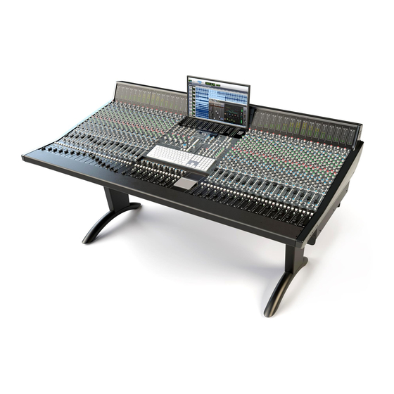
- Page 3 About ORIGIN ORIGIN takes a fresh look at what a large format console needs to do to work in harmony with a modern DAW-driven production studio. The functional design looks back at the ‘ORIGIN’ of in-line consoles for signal flow inspiration, but its circuits are at the cutting edge of SSL’s latest analogue developments.
-
Page 4: Table Of Contents
Mounting the console on the legs (if supplied) Fitting/Removing the Sculpted End Trim Installation in rooms with difficult/awkward access. ORIGIN Master Section About the ORIGIN Master Section and centre section rack layout. VERY IMPORTANT INFORMATION Making Connections Origin Rear View - Power and Audio Connectors... - Page 5 Suggested Patchbay Layout Appendix A - Performance Specification Audio Performance PureDrive™ Channel Input Microphone/Line Amplifier Monitor Input Line Input Amplifier Channel Equaliser Overall Channel Signal Chain Specifications Crosstalk Overall Console Noise Environmental Requirements Appendix B - ORIGIN Block Diagram ORIGIN Installation Guide...
-
Page 6: Safety First
This section contains definitions and warnings, and practical information to ensure a safe working environment. Please take time to read this section before undertaking any installation work. Before use please also refer to the Safety Guide for ORIGIN, which is included in all new console shipments. Definitions ‘Maintenance’... -
Page 7: Safety Earth Connection
Some units (specifically, those fitted with PSU Redundancy) utilise multiple power sources. This is clearly marked on the equipment. The finished installation must also be clearly marked to ensure that all sources of power are removed before servicing work begins. ORIGIN Installation Guide... -
Page 8: Physical Safety
Tools Origin is supplied with a pair of T-handle Module Pullers (SSL Part #53911152A) and a 2mm Allen Key to aide with maintenance of the channel strips. Other tools that may be needed for installation are an 8mm Metric (M8) spanner/socket or adjustable spanner to attach the legs. -
Page 9: Regulatory Information
Safety And Regulations Regulatory Information CE Certification ORIGIN is CE compliant. Note that cables supplied with SSL equipment may be fitted with ferrite rings at each end. This is to comply with the current regulations and these ferrites should not be removed. -
Page 10: Help And Advice
Special Tools and Fasteners Each ORIGIN console is supplied with a pair of M4 thread T-Bar module removal tools (SSL Part No. 53911152A) which fix into the threaded holes that are exposed when the upper and lower channel fixing screws are removed. -
Page 11: Origin Power, Weight And Dimensions
Console Data ORIGIN Power, Weight and Dimensions Approx. Dimensions are shown in mm [and feet-inches] in the diagrams below. Other specs are: Approximate Weight: 357 lb / 162 kg including legs and trim ( 315 lb / 143 lb excluding legs) Approximate Power Consumption: Typically <900 Watts, 1200 Watts maximum when on... -
Page 12: General Precautions
IMPORTANT - ORIGIN Frame Structure and Manoeuvering The Console. The structure of ORIGIN is built on a strong steel U-beam which spans the width of the base of the console. Only this should be used to lift and manoeuver the console when using a forklift or other mechanical lifting aid. -
Page 13: Dismantling The Shipping Crate
Remove Foam Brace Unbolt and Remove All Four Wood Sides Remove Console From Base CONSOLE = 162 kg (357 lb) 4 PEOPLE MUST LIFT AND USE LIFTING APPARATUS! Remove Foam Base Tray Remove Optional Legs From Base** **If Purchased ORIGIN Installation Guide... -
Page 14: Mounting The Console On The Legs (If Supplied)
Lift** the console and gently place it onto its rear. The console will rest in a near vertical position on the rear panel heatsinks and the cable tray mounted on the rear edge. **The console is heavy! Several strong people will be needed for this activity. ORIGIN Installation Guide... - Page 15 With the legs attached securely, the console can be lifted to it's final position. The rubber feet at the base of the legs have a small amount of screw adjustment allowing adjustment for uneven floors. ORIGIN Installation Guide...
-
Page 16: Fitting/Removing The Sculpted End Trim
Keyslots in sculpted end trim interlock with studs in end of ORIGIN console frame Removing the end trim starts with removing the three... -
Page 17: Installation In Rooms With Difficult/Awkward Access
For further information please contact SSL’s Support Department at: support@solidstatelogic.com. ORIGIN Installation Guide... -
Page 18: Origin Master Section
About the ORIGIN Master Section and centre section rack layout. The ORIGIN Master Section is designed to be the heart of a flexible, configurable central layout. The 6U 19" rack width is designed to be re-positionable for different application priorities. As standard, the master section is fitted in the bottom 6U of the 12U central rack layout and there are two 3U panels blank panels above. - Page 19 The lower right blank area next to the Stereo Group faders has an Apple Magic Trackpad placed on it to show for scale. IMPORTANT: Please read the VERY IMPORTANT INFORMATION on the previous page before fitting any electronic devices into the centre section racking. ORIGIN Installation Guide...
- Page 20 Trackpad. **NOTE: Moving The 6U Master Section The 6U ORIGIN Master Section has many of the console audio and control signals wired to it. Please exercise anti-static precautions before moving and take great care to ensure no cables are snagged or disconnected when moving.
- Page 21 With any rack units that restrict air flow through the centre section, ventilation rack panels must be used to keep airflow through the Master Section. MAXIMUM depth available includes cables, connectors and cable bend radiuses. Cable Entry 100mm x 430mm 4.0in x 17.0in ORIGIN Installation Guide...
- Page 22 Notes Notes ORIGIN Installation Guide...
-
Page 23: Making Connections
Making Connections Making Connections Origin Rear Connector Locations ORIGIN Installation Guide... -
Page 24: Origin Rear View - Power And Audio Connectors
Making Connections Origin Rear View - Power and Audio Connectors Location of the main audio and power connections are shown in the diagram below looking towards the rear of the console. IEC Power Inlets and Main Power Switch XLR connectors to Channel Mic Pre-Amplifiers... -
Page 25: Channel Db-25 Connectors
Ch Line IP 22 Ch Line IP 30 Ch Line IP 7 Ch Line IP 15 Ch Line IP 23 Ch Line IP 31 Ch Line IP 8 Ch Line IP 16 Ch Line IP 24 Ch Line IP 32 ORIGIN Installation Guide... -
Page 26: Channel Db-25 Pinouts Cont'd
SF Ins Snd 22 SF Ins Snd 30 SF Ins Snd 7 SF Ins Snd 15 SF Ins Snd 23 SF Ins Snd 31 SF Ins Snd 8 SF Ins Snd 16 SF Ins Snd 24 SF Ins Snd 32 ORIGIN Installation Guide... -
Page 27: Channel Db-25 Pinouts Cont'd
Direct Out 29 Direct Out 6 Direct Out 14 Direct Out 22 Direct Out 30 Direct Out 7 Direct Out 15 Direct Out 23 Direct Out 31 Direct Out 8 Direct Out 16 Direct Out 24 Direct Out 32 ORIGIN Installation Guide... -
Page 28: Master Section Db-25 Connectors
St Grp IP 2R St Grp IP 6R St Grp IP 3L St Grp IP 7L St Grp IP 3R St Grp IP 7R St Grp IP 4L St Grp IP 8L St Grp IP 4R St Grp IP 8R ORIGIN Installation Guide... -
Page 29: Master Section Db-25 Pinouts Cont'd
Mix Ins Snd L Oscillator Out Mix Ins Snd R Listen Mic Out Mix OP L Foldback Out AL Mix OP R Foldback Out AR Foldback Out BL Foldback Out BR Studio L Ext TB Out Studio R ORIGIN Installation Guide... - Page 30 9-Way F D-type Red Light Relay Normally Open Contact R1 Common Normally Closed Contact R1 Normally Open Contact R2 Common Normally Closed Contact R2 R1 and R2 are separate relays, both operated by the Red Light Switch ORIGIN Installation Guide...
-
Page 31: Suggested Patchbay Layout
Making Connections Suggested Patchbay Layout ORIGIN Installation Guide... -
Page 32: Appendix A - Performance Specification
<0.0003% at 1 kHz (20 Hz to 20 kHz) (-10 dBu applied, +20 dB gain) @ 10 kHz <0.0009% at 10 kHz (20 Hz to 40 kHz) CMRR > 65 dB 20 Hz to 20 kHz Equivalent Input Noise (EIN) 150 Ω termination, maximum gain <-104 dBu ORIGIN Installation Guide... -
Page 33: Channel Equaliser
-3 dB high rolloff >70 kHz 20 Hz to 20 kHz Main Mix Bus +0/-0.3 dB -3 dB high rolloff >70 kHz 20 Hz to 20 kHz Auxilliary Buses +0/-0.3 dB -3 dB high rolloff >70 kHz Pot centre detent accuracy: +/-1 dB, typically <0.5 dB ORIGIN Installation Guide... -
Page 34: Crosstalk
(Pan to centre) 16 channels routed <-85 dBu 24 channels routed <-83 dBu 32 channels routed <-79 dBu Environmental Requirements Temperature range: Operating: +1 to 30 °C (+34 to 86 °F). Storage: -20 to 50 °C (-4 to 122 °F). ORIGIN Installation Guide... -
Page 35: Appendix B - Origin Block Diagram
Appendix B Appendix B - ORIGIN Block Diagram ORIGIN Installation Guide... - Page 36 Notes Notes ORIGIN Installation Guide...
- Page 37 www.solidstatelogic.com...
Need help?
Do you have a question about the ORIGIN and is the answer not in the manual?
Questions and answers