Advertisement
Quick Links
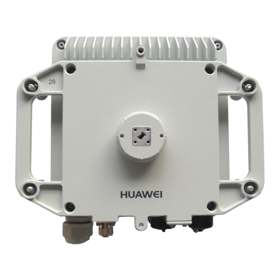
RTN 310 V100R006
Quick Installation Guide
BOM: 31507452
Issue: 01
Date: 2015-10-30
Copyright © Huawei Technologies Co., Ltd. 2015. All rights reserved.
No part of this document may be reproduced or transmitted in any form or by any means without prior
written consent of Huawei Technologies Co., Ltd.
Huawei Technologies Co., Ltd.
Address:
Huawei Industrial Base
Bantian, Longgang
Shenzhen 518129
People's Republic of China
Website:
http://www.huawei.com
Email:
support@huawei.com
RTN 310 packing list
No.
Item
1
2
3
4
5
6
7
8
Description
RTN 310 module
Auxiliary material package
7.6 mm-wide outdoor binding strap
3.6 mm-wide outdoor binding strap
Waterproof labels for outdoor cables
Engineering labels for indoor cables
Waterproof tape
RTN 310 Quick Installation Guide
01
Advertisement

Related Manuals for Huawei OptiX RTN 310


Summary of Contents for Huawei OptiX RTN 310
- Page 1 Waterproof labels for outdoor cables Engineering labels for indoor cables Copyright © Huawei Technologies Co., Ltd. 2015. All rights reserved. No part of this document may be reproduced or transmitted in any form or by any means without prior written consent of Huawei Technologies Co., Ltd.
-
Page 2: Safety Precautions
Do not work with electrical current in elevated or exposed locations during a Anti-corrosion measures are required if the RTN 310 is installed in an area prone thunderstorm. to corrosion. Contact your local Huawei office for details. A location is corrosion- Extreme weather conditions prone if it is: •... - Page 3 Safety Precautions Power over Ethernet (working with the RTN 900) Avoiding leaving any Ethernet service cable unconnected Do not leave any Ethernet service cable unconnected (see Figure 1). If an Ethernet service port is not in use, remove the cable from it and fasten a PG cover or protective cover onto it. Figure 1 Avoiding leaving any Ethernet service cable unconnected P&E...
- Page 4 Installing the RTN 310 Components Appearance and ports Appearance and ports of the hybrid coupler Cables Front view Top view PGND cable Standby tributary port Base of a ground clip OT terminal 4 x Spring screw Main tributary port •Two types of terminals (ground bar terminal and U-shaped terminal) Handle Oblique view are available for a ground clip.
- Page 5 •The recommended USB flash drive is Netac U208 with a 4 GB capacity. •If a different model or capacity is required, contact your local Huawei office. •The appearance of a USB flash drive on the left is for reference only.
- Page 6 Terminating an Outdoor Network Cable with Shielded RJ45 Connectors Prepare an outdoor network cable Arrange the core wires according to the pin assignments and cut them Prepare the following tools. Strip the cable. and shielded RJ45 connectors. neatly (exposing a length of 12 mm). 8: brown 7: white and brown 6: green...
- Page 7 Terminating an Indoor PI Power Cable with an EPC4 Connector Components of an EPC4 connector (EPC is the Use a screwdriver to push the sliding blocks until Insert conductors. Strip off the sheath of conductors. abbreviation for easy power connector.) the in-position mark is completely exposed.
- Page 8 Installing the RTN 310 Installing the RTN 310 at the Edge of a Mobile Backhaul Network (Indoor PI Used) Cover unused ports with caps/PG covers. Retain removed caps for future use. Before installing the RTN 310, remove the protective cover and film on the antenna port. Otherwise, signal transmission will be affected. Different methods can be used to change the polarization direction of antennas.
- Page 9 Installing the RTN 310 Installing the RTN 310 at the Edge of a Mobile Backhaul Network (Outdoor PI Used) Cover unused ports with caps/PG covers. Retain removed caps for future use. Before installing the RTN 310, remove the protective cover and film on the antenna port. Otherwise, signal transmission will be affected. Different methods can be used to change the polarization direction of antennas.
- Page 10 Installing the RTN 310 Installing the RTN 310 Co-sited with a Dock Cover unused ports with caps/PG covers. Reserve removed caps for future use. Before installing the RTN 310, remove the protective cover and film on the antenna port. Otherwise, signal transmission will be affected. Different methods can be used to change the polarization direction of antennas.
- Page 11 Installing the RTN 310 Installing the RTN 310 at a 2x(1+0) Aggregation Site Cover unused ports with caps/PG covers. Retain removed caps for future use. Before installing the RTN 310, remove the protective cover and film on the antenna port. Otherwise, signal transmission will be affected. Different methods can be used to change the polarization direction of antennas.
- Page 12 Installing the RTN 310 Installing the RTN 310 That Works with the RTN 900 Cover unused ports with caps/PG covers. Reserve removed caps for future use. Before installing the RTN 310, remove the protective cover and film on the antenna port. Otherwise, signal transmission will be affected. Different methods can be used to change the polarization direction of antennas.
- Page 13 Installing the RTN 310 Installing the RTN 310 at an XPIC Site CAUTION Cover unused ports with caps/PG covers. Retain removed caps for future use. Different methods can be used to change the polarization direction of antennas. If the method provided in this document is not suitable for the type of antennas you have, use the method provided in the installation manual delivered with your antennas.
- Page 14 Installing the RTN 310 Installing the RTN 310 at a 1+1 LAG Mode Site Cover unused ports with caps. Reserve the removed caps. Before installing the RTN 310, remove the protective cover and film on the antenna port. Otherwise, the signal transmission will be affected. Different methods can be used to change the polarization direction of antennas.
- Page 15 Installing the RTN 310 Installing the RTN 310 at a 1+1 Optical Splitter Mode Site Cover unused ports with caps. Reserve the removed caps. Before installing the RTN 310, remove the protective cover and film on the antenna port. Otherwise, the signal transmission will be affected. Different methods can be used to change the polarization direction of antennas.
- Page 16 Aligning Antennas Appendix Relationship Between RSSI Port Voltage and Receive Signal Level Waterproofing Ground Clips 1. Wrap one layer of PVC tape around the exposed part of a group clip. 2. Wrap three layers of waterproof tape outside the PVC tape. 3.
- Page 17 Appendix Installing the Waterproof Socket for the Outdoor Fiber Appearance of the waterproof socket Thread the outdoor fiber through the waterproof socket Optional: Remove the waterproof block at the end of the rubber washer. CAUTION If you only assembly the waterproof block but do not Collar Rubber washer...
- Page 18 Installation Reference Installing the RTN 310 Change the polarization direction of a single-polarized antenna to horizontal. Apply petroleum jelly around the exterior side ① of the feed. Do not apply petroleum jelly to the end face ② of the feed. V (default) Refer to the antenna installation guide for information on how to ②...
- Page 19 Installing Reference Installing the RTN 310 Install a split-mount installation bracket assembly to a pole. Install the RTN 310 on the split-mount installation bracket assembly. 1. Install the RTN 310 ① on a conversion bracket ② and tighten the four captive screws ③ in a diagonal 1.
- Page 20 Installation Reference Installing the RTN 310 Install a flexible waveguide fixing set. Install the flexible waveguide fixing set on a pole. Secure the flexible waveguide. Components of a flexible waveguide fixing set Use the hose clamp to install the flexible waveguide 1.
- Page 21 Installation Reference Installing the RTN 310 Install an outdoor fiber. Install the PGND cable of the RTN 310. CAUTION 1. Insert an SFP optical module into the GE(o)/COMBO port of the RTN 310. The port provides mis-insertion For details on the anticorrosion prevention function.
- Page 22 Installation Reference Installing the RTN 310 Install a 1+1 cascade fiber. 1. Insert an SFP optical module into the COMBO port of the RTN 310. The port provides mis-insertion prevention function. If you feel resistance in inserting the module, rotate it and insert it again. 2.
- Page 23 Installation Reference Ground Points of the RTN 310 (Indoor PI) Select ground points for the P&E cable. Ground the P&E cable at the following positions: 1. About 0.5 m to 1 m away from the port 2. About 1 m before the cable leaves the tower and runs toward the outdoor cable tray 3.
- Page 24 Installation Reference Installing an Indoor PI Insert a PI into a slot on the auxiliary mounting bracket and Optional: Installing a PI in an ETSI Cabinet tighten the captive screws on the mounting ears. Tighten floating nuts. When you tighten floating nuts, reserve a heat dissipation space of at least 25 mm on the left and right sides of the auxiliary mounting bracket.
- Page 25 Installation Reference Installing an Indoor PI Optional: Installing a PI on a Wall Tighten floating nuts. Mark and drill holes in the wall. Hold the PI up to the wall and mark the drilling positions. Drill the holes and insert the fixing bolts. The positions of the holes should allow a heat dissipation space of at least 50 mm above and below the auxiliary mounting bracket.
- Page 26 Installation Reference Installing an Indoor PI Laying Out Indoor PI Cables Optional: Installing a PI in an Outdoor Cabinet Install the GE cable used for providing power of Ethernet. Install a PI in an outdoor cabinet. When you install a PI in an outdoor cabinet, P&E port ensure that the ground...
- Page 27 Installation Reference Installing an Outdoor Optical Splitter Loosen the hex socket screws. Open the cover of the outdoor optical splitter. Optional: Install the outdoor optical splitter on a wall. 4 mm hex key Cable distribution area 3.1 Use a scribe template to determine the positions of mounting holes and use a scribe pen to mark them.
- Page 28 Installation Reference Installing an Outdoor Optical Splitter Optional: Install the outdoor optical splitter on a pole. 4.2 Secure the outdoor optical splitter on the mounting assembly and tighten the lower hose clamp. 4.1 Install the mounting assembly on a pole. Loosen the screw on the hose clamp.
- Page 29 Equipment Distribution Area Main RTN 310 Receive GE port on the main OptiX RTN 310 Transmit GE port on the main OptiX RTN 310 Standby RTN Receive GE port on the standby OptiX RTN 310 Transmit GE port on the standby OptiX RTN 310...
- Page 30 Installation Reference Installing an Outdoor Optical Splitter Close the cover of the outdoor optical splitter. 4 mm hex key Tighten the hex socket screws to ensure that the outdoor optical splitter is waterproof. 58/59 >>...
- Page 31 Installation Reference Ground Points of the RTN 310 (Outdoor PI) Ground points of the RTN 310 and PI: Point 1: Ground the RTN 310 using a PGND cable. Point 2: Ground the P&E cable using a ground clip at a position about 0.5 m to 1 m away from the port. Lightning rod Point 3: Ground the P&E cable using a ground clip at a position about 1 m before the cable leaves the tower.
- Page 32 Checking the Installation Checking the Cables of the RTN 310 Check Item All outdoor connectors and ground clips are waterproofed and sealed. Cable connectors are assembled correctly and securely. Cables are not bent or twisted, and the shield layer is not exposed. There is a drip loop in the cable after it leaves the RTN 310.
- Page 33 Installation Reference Powering On the RTN 310 Supplied by an Indoor PI Powering On the RTN 310 Supplied by an Outdoor PI Powering On the RTN 310 Working with the RTN 900 Caution Caution Caution • Before powering on the equipment, ensure that: Before powering on the equipment, ensure that: •...
- Page 34 Installation Reference Loading NE data by using a USB flash drive or by directly connecting the Web LCT to the RTN 310 Loading NE data by connecting the Web LCT to the RTN 310 through Wi-Fi NOTE For details about how to connect the Web LCT to the RTN 310 through Wi-Fi to load NE data, see the Commissioning and Configuration Guide.