Table of Contents
Advertisement
Quick Links
VER:1.0 │
│ 22.04.2015
ABB-Welcome
Pos : 2 /Di nA4 - Anleitung en Online/Inhalt/KN X/D oorEntr y/83220- AP- xxx/Titelbl att - 83220-AP- xxx - ABB @ 19\mod_1323249806476_15.doc x @ 111084 @ @ 1
M25102xC
M25102xA-x-
M25102xPx.
M25102xK-x.
M25102xCR.
5102xDN
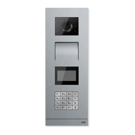
Outdoor station
=== Ende der Liste für T extmar ke Cover ===
Advertisement
Table of Contents

Related Manuals for ABB M25102xC Series


Summary of Contents for ABB M25102xC Series
- Page 1 VER:1.0 │ │ 22.04.2015 ABB-Welcome Pos : 2 /Di nA4 - Anleitung en Online/Inhalt/KN X/D oorEntr y/83220- AP- xxx/Titelbl att - 83220-AP- xxx - ABB @ 19\mod_1323249806476_15.doc x @ 111084 @ @ 1 M25102xC M25102xA-x- M25102xPx. M25102xK-x. M25102xCR. 5102xDN Outdoor station...
-
Page 2: Table Of Contents
Pos : 4 /Busch-J aeger (Neus truktur)/M odul-Str uktur/Online-Dokumentation/Inhal ts verz eic hnis (--> Für alle D okumente <--)/Inhalts verz eichnis @ 19\mod_1320649044386_15.doc x @ 109653 @ @ 1 Safety ......................4 Intended use ....................4 Environment ....................4 ABB devices ................. 5 Terminal description ..................6 Audio module ................6 4.1.1 Lock connected with terminals 3&4 .......... - Page 3 ABB-Welcome General installation instructions ..........56 Mounting ..................57 === Ende der Liste für T extmar ke TOC === — 3 —...
-
Page 4: Safety
The device contains valuable raw materials which can be recycled. Therefore, dispose of the device at the appropriate collecting depot. Pos : 12 /DinA4 - Anl eitungen Onli ne/Ueberschriften/2./ABB Geraete @ 19\mod_1323162843832_15.doc x @ 110875 @ 2 @ 1 — 4 —... -
Page 5: Abb Devices
ABB devices Pos : 13 /Busc h-J aeg er (Neustr uktur)/Modul- Struktur /Online-Dokumentati on/U mwel t (--> Für alle D okumente <--)/Hinweis e/Hi nweis - U mwelt - ABB El ektr ogeräte @ 19\mod_1323162745839_15.doc x @ 110867 @ @ 1 All packaging materials and devices from ABB bear the markings and test seals for proper disposal. -
Page 6: Terminal Description
ABB-Welcome Terminal description Terminal description Audio module Fig. 1 Terminal description Function LED flashes slowly, indicating a call established LED flashes fast, indicating that the system is busy LED illuminates, indicating possible communication. LED illuminates, indicating the door is unlocked Call pushbuttons —... - Page 7 ABB-Welcome Terminal description Fig. 2 Terminal description Functions Connector for camera module Connector for device software update Plug-in clamps (COM-NC-NO) for floating output, door opener (30VAC/DC Plug-in clamps (Lock-GND) for door opener (18V 4A impulsive, 250 mA holding) Plug-in clamps (DC-GND) for additional power supply...
- Page 8 ABB-Welcome Terminal description Set feedback tones for push buttons: ON/OFF Configure push buttons in a single column or double column mode (ON= double column; OFF= single column) Configure functions of the 1 push button. 3->OFF, 4->OFF=call indoor station/call indoor station;...
-
Page 9: Lock Connected With Terminals 3&4
ABB-Welcome Terminal description 4.1.1 Lock connected with terminals 3&4 — 9 —... -
Page 10: Camera Module
ABB-Welcome Terminal description Camera module Fig. 3 Terminal description — 10 —... - Page 11 ABB-Welcome Terminal description Functions Connector for additional analog camera Connector for audio module Jumper for setting the video format: PAL /NTSC Adjust the camera view area — 11 —...
-
Page 12: Analog Camera Connected With Terminal 1
ABB-Welcome Terminal description 4.2.1 Analog camera connected with terminal 1 All the cameras with the video output of 1Vp-p 75Ω ,CVBS (composite video broadcast signal) can be connected with the camera module. Generally, the transmission distance from analog camera to the outdoor station can reach up to 50 meters by Coax cables or about 10 meters by other types of cables. - Page 13 ABB-Welcome Terminal description — 13 —...
-
Page 14: Detached Camera Connection
ABB-Welcome Terminal description 4.2.2 Detached camera connection Camera module can be used as a detached camera, and the wiring is shown in below. 3 pairs 2-wire bus together Max:10 metres — 14 —... - Page 15 ABB-Welcome Terminal description — 15 —...
-
Page 16: Push Button Module
ABB-Welcome Terminal description Push button module Fig. 4 Terminal description Functions Connector for previous module Connector for next module — 16 —... - Page 17 ABB-Welcome Terminal description Fig. 5 Terminal description Functions Regardless of the structure of the push button module, the button numbers are listed from the top to bottom and from left to right (in the double column mode) Lighting switch / call guard unit function is always assigned to the 1 button.
-
Page 18: Keypad Module
ABB-Welcome Terminal description Keypad module Fig. 6 Terminal description Functions Program button Connector for previous module Connector for device software update USB connector for the connection to the PC : download/upload the configuration Connector for next module — 18 —... - Page 19 ABB-Welcome Terminal description Pic 1 Pic 2 Fig. 7 Terminal description Functions Call resident A visitor inputs an indoor station number (001) or apartment number (e.g. 0101, programmed in advance) to call a resident. *Also, the visitor can select a resident name with the button...
-
Page 20: Display And Card Reader Module
ABB-Welcome Terminal description engineering configuration menu. The initial system password is 345678 and it can be modified by the administrator. Display and card reader module Fig. 8 Terminal description Functions Program button Connector for previous module Connector for device software update... - Page 21 ABB-Welcome Terminal description Fig. 9 Terminal description Functions LCD display Support ID or IC card. Swipe the registered card to release the door lock. The card can be programmed through the module itself, or using a PC to download the program file.
- Page 22 ABB-Welcome Terminal description Work 125KHz Frequency Standard ISO18000-2 Support card EM4100, EM4205, EM4305, EM4450, TK4100, T5567 / T5577 Compatible HID 2 Output Wiegand 26, 34bit format M251022CR:Display module with IC card reader Work 13.56MHz Frequency Standard ISO 14443A Support card Mifare One S50/S70,etc.
-
Page 23: Nameplate Module
ABB-Welcome Terminal description Nameplate module Fig. 10 Terminal description Functions Connector for previous module Connector for next module Labeling of the nameplate module can be printed by the labelling tool of the Welcome configuration software. — 23 —... - Page 24 ABB-Welcome Terminal description Pos : 18 /DinA4 - Anl eitungen Onli ne/Ueberschriften/1./Bedi enung @ 18\mod_1302613924165_15.doc x @ 103365 @ 1 @ 1 — 24 —...
-
Page 25: Operation
ABB-Welcome Operation Operation Pos : 19 /DinA4 - Anl eitungen Onli ne/Ueberschriften/2./Nor maler Betrieb @ 18\mod_1302768820965_15.doc x @ 103540 @ 2 @ 1 Pushbutton outdoor station Fig. 11 Pushbutton outdoor station Pos : 20 /DinA4 - Anl eitungen Onli ne/Ueberschriften/3./Bedi enel emente @ 20\mod_1323260220559_15.doc x @ 111647 @ 3 @ 1 5.1.1... - Page 26 ABB-Welcome Operation Fig. 12 Addressing Functions 3->OFF, 4->OFF Call apartment 01 Call apartment 02 Call apartment 03 Fig. 13 Addressing Functions 3-> ON, 4->OFF Switch on light. The light is connected with a switch actuator, and the address of the switch actuator must be same as the address of this outdoor station.
- Page 27 ABB-Welcome Operation Guard unit Fig. 14 Addressing Functions 3-> OFF, 4-> ON Call the guard unit. If there are multiple guard units in the same section, all guard units will ring at the same time when a visitor presses the button “call guard unit”.
- Page 28 ABB-Welcome Operation 3-> ON, 4-> ON Switch on lights Call guard unit Call apartment 01 Configure push button in a single column or double column modes Fig. 16 Addressing Functions 2-> OFF Call apartment 01 Call apartment 02 Call apartment 03 Call apartment 04 —...
- Page 29 ABB-Welcome Operation Fig. 17 Addressing Functions 2-> ON Call apartment 01 Call apartment 02 Call apartment 03 Call apartment 04 Call apartment 05 Call apartment 06 Call apartment 07 Call apartment 08 — 29 —...
-
Page 30: Setting The Language For The Voice Messages
ABB-Welcome Operation Guard unit Fig. 18 Addressing Functions 2-> ON,3-> ON, 4-> ON Switch on lights Call the guard unit Call apartment 01 Call apartment 02 Call apartment 03 Call apartment 04 Call apartment 05 Call apartment 06 5.1.2 Setting the language for the voice messages (if the audio module has a speech synthesis function) If the audio module with a speech synthesis function (M251024A-.) is assembled, the... - Page 31 ABB-Welcome Operation After choosing the right language, hold this button to save and exit the setting. button Single column Double column Fig. 19 Addressing Pushbutton outdoor station used as gate station If pushbutton outdoor station is set as a gate station, gateway as an important system device must be used and it must be set as floor gateway mode.
- Page 32 ABB-Welcome Operation Detailed information please refer to “Gateway “user manual ,floor gateway chapter. Pos : 71 /DinA4 - Anl eitungen Onli ne/Ueberschriften/3./Absc hlus s widerstand @ 19\mod_1321958079906_15.doc x @ 110083 @ 3 @ 1 Pos : 72 /DinA4 - Anl eitungen Onli ne/Inhalt/KN X/D oor Entr y/Bedienung/Absc hl uss widerstand setzen 83220-AP- xxx @ 19\mod_1310723392369_15.doc x @ 107841 @ @ 1...
-
Page 33: Pushbutton Outdoor Station With Display Module
ABB-Welcome Operation Pushbutton Outdoor Station with display module The Display and card reader module can be assembled with a push button outdoor station and the user can swipe cards to open the door. For such combination, a master card is needed for an electrician to manage this outdoor station. -
Page 34: Pushbutton Outdoor Station With Keypad Module
ABB-Welcome Operation There is a 5s countdown for each option. Swipe the MASTER card again within 5s to change to the next option. Or, 5s over, the current option will be chosen. 30s Over, to exit the settings menu. Swipe the MASTER... - Page 35 ABB-Welcome Operation Gate Station: #* system password # => => Modify "system password" #* system password # => => Enter new password (6-8 bits) # => Enter the password again # Modify "door open code" #* system password # =>...
- Page 36 ABB-Welcome Operation #* system password # => => *Reset the system password of keypad module: It is possible to reset the system password to factory-setting if you have forgotten it. The restoration of default factory settings does not delete the rest of the information programmed on the system, such as user names and other settings.
-
Page 37: Keypad Outdoor Station
ABB-Welcome Operation Keypad outdoor station 5.4.1 Call a resident (3 types) By physical address Physical address is the internal code which the outdoor station will send through the bus connection to indoor stations or other devices in the system. For each apartment, physical address means the address of an indoor station which is installed in the apartment. -
Page 38: Call The Guard Unit
ABB-Welcome Operation Physical Add.: Logic Add.: Turn on the “logic address” call mode #* system password # => system setting => Configuration => Call mode Call Mode_______ No. Of digit: ∧ Physical Add. ==> Logic Add.-------- By resident name (Remarks: this function is only available for the outdoor station with a keypad module (M251021K-.).) -
Page 39: If An Indoor Station Is In "Leave Home Mode
ABB-Welcome Operation Accept the call 30 s 120 s ==> Guard Unit Guard Unit 5.4.3 If an indoor station is in "leave home mode" If an indoor station works in the “leave home mode”, a visitor can record a message for the resident after entering the following interface. - Page 40 ABB-Welcome Operation Call from an outdoor Guard unit transfers the GU accept the call station to an indoor call to an indoor station station 30 s 120 s ==> ==> ==> Guard Unit Guard Unit 120 s Andy — 40 —...
-
Page 41: System Settings
ABB-Welcome Operation 5.4.5 System settings (During setting, press “#” to confirm, press “*” to cancel, default system password is 345678): Enter the system setting menu #* system password # Menu__________ Configurations-- ∧ Access Control Configurations (1) Set the device as an Outdoor Station or a Gate Station. - Page 42 ABB-Welcome Operation Call Mode_______ ∧ Physical Add.● Logic Add.: Set the call mode by a Logic Code,No. of digits (1-8 digits): #* system password # => Configurations # => Call mode # => Logic Code # Call Mode_______ ∧ Physical Add.
- Page 43 ABB-Welcome Operation Meanwhile, users can set their own passwords with indoor stations, totally, 6000 passwords can be stored. Set the door open password ON/OFF (default: 123456) #* system password # => Access Control # => Door open code # =>...
- Page 44 ABB-Welcome Operation #* system password # => Access control # => Proximity card # => Register card # Enter Card No.: Enter Card No.: ==> 0123456 0123456 Done! Delete cards: #* system password # => Access control # => Proximity card # =>...
- Page 45 ABB-Welcome Operation Resident names must be associated with physical address. Add the contact by logic address #* system password # => Contact # => Add # => Logic add. # Physical Add.: Logic Add.: Logic address must be associated with physical address.
- Page 46 ABB-Welcome Operation #* system password # => Contact # => Delete # => User Names # _______________ -- ∧ Alexander.G Bodin.K Delete the contact by logic address #* system password # => Contact # => Delete # => Logic add. # Enter Logic Add.:...
- Page 47 ABB-Welcome Operation 2013-01-01 Done! ==> 07:00 (2) Door Open Time #* system password # => Settings # => Door Open Time # => Time 1-10s (default: 3s) => Lock(NC-NO-C) means the lock connected with COM-NC-NO terminals. Lock(NC-NO-C) Open Done! ==>...
- Page 48 #* system password # => Settings # => Welcomesg. # New Message: Done! ==> ABB Welcome! “#“ to Confirm Max 64 characters can be entered. (6) Setting the Wiegand output digits #* system password # => Settings # => Wiegand Output # Wiegand Output__ ●...
- Page 49 ABB-Welcome Operation Setting the lock which will be released when swiping the registered card: 1st (LOCK-GND): the lock connected with the LOCK-GND terminals will be released when swiping the card. 2ND (NC-NO-COM): the lock connected with the NC-NO-COM terminals will be released when swiping the card.
- Page 50 ABB-Welcome Operation A “di” will be sounded and the system password will be reset to the default (345678). Pos : 67 /DinA4 - Anl eitungen Onli ne/Ueberschriften/2./Rei nigung @ 19\mod_1310733980533_15.doc x @ 107853 @ 2 @ 1 — 50 —...
-
Page 51: Keypad Outdoor Station Without Display
ABB-Welcome Operation Keypad outdoor station without display (Camera + audio+ keypad) 5.5.1 Calling a resident, just input physical address In standby mode, a visitor can press the physical address corresponding to the residence that you want to call directly, from 001 to 250. - Page 52 ABB-Welcome Operation => Modify the "system password" #* system password # => => Enter new password (6-8 bits) # => Enter the password again # Modify the "door open code" #* system password # => => Enter new door open code (6-8 bits) # =>...
-
Page 53: Advanced Configuration
ABB-Welcome Advanced configuration Pos : 70 /DinA4 - Anl eitungen Onli ne/Ueberschriften/2./Geraeteei nstellungen @ 18\mod_1302768847744_15.doc x @ 103548 @ 2 @ 1 Advanced configuration Connect to the PC to configure the keypad or display Fig. 25 Pos : 75 /Busc h-J aeg er (Neustr uktur)/Modul- Struktur /Online-Dokumentati on/Steuermodul e - Onli ne-D okumentation (--> F ür all e D okumente <--)/++++++++++++ Seitenumbruc h ++++++++++++ @ 9\mod_1268898668093_0.doc x @ 52149 @ @ 1... -
Page 54: Technical Data
ABB-Welcome Technical data Pos : 76 /DinA4 - Anl eitungen Onli ne/Ueberschriften/1./Tec hnisc he D aten @ 18\mod_1302615863001_15.doc x @ 103416 @ 1 @ 1 Technical data Pos : 77 /DinA4 - Anl eitungen Onli ne/Inhalt/KN X/D oor Entr y/83220-AP- xxx/T ec hnische D aten - 83220-AP- xxx @ 18\mod_1303212854559_15.doc x @ 103705 @ @ 1... -
Page 55: Mounting / Installation
ABB-Welcome Mounting / Installation Pos : 79 /Busc h-J aeg er (Neustr uktur)/Modul- Struktur /Online-Dokumentati on/Übersc hriften (--> Für alle D okumente <--)/1. Ebene/M - O/Montage / Installation @ 18\mod_1302613966111_15.doc x @ 103373 @ 1 @ 1 Mounting / Installation Pos : 80 /Busc h-J aeg er (Neustr uktur)/Modul- Struktur /Online-Dokumentati on/Sic herheit (-->... - Page 56 ABB-Welcome Mounting / Installation • Use suitable personal protective clothing. • Use only suitable tools and measuring devices. • Check the type supply network (TN system, IT system, TT system) to secure the following power supply conditions (classic connection to the ground, protective grounding, necessary additional measures, etc.).
- Page 57 ABB-Welcome Mounting / Installation Pos : 84 /Busc h-J aeg er (Neustr uktur)/Modul- Struktur /Online-Dokumentati on/Übersc hriften (--> Für alle D okumente <--)/2. Ebene/M - O/Montage @ 18\mod_1302615960458_15.doc x @ 103424 @ 2 @ 1 Mounting Pos : 85.1 /DinA4 - Anl eitungen Onli ne/Inhalt/KN X/DoorEntr y/83220-AP- xxx/M ontag e - M odul e/Montage - Montagedose -- 83220-AP- xxx @ 19\mod_1323250406848_15.doc x @ 111098 @ @ 1 Prepare a pair of gloves to protect yourself from cutting.
- Page 58 ABB-Welcome Mounting / Installation Dimension Audio module Camera module Nameplate module Pushbutton module Keypad module Display and card reader module — 58 —...
- Page 59 ABB-Welcome Mounting / Installation Cover frame — 59 —...
- Page 60 ABB-Welcome Mounting / Installation Flush-mounted — 60 —...
- Page 61 ABB-Welcome Mounting / Installation Rain hood — 61 —...
- Page 62 ABB-Welcome Mounting / Installation Components of the Outdoor Station Fig. 26 Mounting Functions Cover frame Modules Flash-mounted box Rain hood — 62 —...
- Page 63 ABB-Welcome Mounting / Installation Mount each module at the cover frame Fig. 27 Mounting Insert each module into the cover frame from behind until they click in place. All modules can be inserted, e.g. the camera module, audio module, push button module, keypad module, display and card reader module, nameplate module.
- Page 64 ABB-Welcome Mounting / Installation Modules wiring Fig. 28 Modules wiring Use cables to connect the modules together one by one. Ensure that the audio module is connected next to the camera module. — 64 —...
- Page 65 ABB-Welcome Mounting / Installation The distance zones for the installation of the outdoor station When selecting the installation site ensure that the minimum distance to the right side is adhered to for the removal of the end strip. — 65 —...
- Page 66 ABB-Welcome Mounting / Installation Wires Fig. 29 Mounting Prepare the installation box. Strip the wires. – The insulated section of the cable end must not be longer than 10 mm. Assemble the frame into the flush-mounted box Fig. 30 Mounting...
- Page 67 ABB-Welcome Mounting / Installation Hang the device in the installation box. Fasten the safety loop. Connect the wires into the enclosed clamp and plug the clamp onto the contact pins; Fold the device and shut it until it audibly snaps in.
- Page 68 ABB-Welcome Mounting / Installation Fig. 32 Flush-mounted with a rain hood Option 3: Surface-mounted with a rain hood Fig. 33 Surface-mounted with a rain hood — 68 —...
- Page 69 ABB-Welcome Mounting / Installation Dismounting outdoor station Fig. 34 Mounting Use the enclosed mounting tool to remove the end strip. Remove the screw that are used to fix the cover frame. Push up and pull out the outdoor station on the bottom of the cover frame.
- Page 70 ABB-Welcome Mounting / Installation Dismount the module from one side of the module. Take out the modules. Replace the name plates Fig. 36 Mounting Remove the pushbutton cover and write the user names on the label. *Use a piece of labelling A4 sheet with software necessary for the correct format and print the labels.
- Page 71 ABB-Welcome Mounting / Installation Adjust the angle of the camera in 4 directions(up, down, right and left) Screw on the camera. — 71 —...
- Page 72 ABB-Welcome Mounting / Installation Extension of the outdoor station Fig. 38 Mounting Make a hole for the cable. Use the joining fixtures to assemble the flush-mounted boxes horizontally. Run the connection wires between the boxes for modules connection. *The extension is useful for multi-outdoor stations connection.
- Page 73 We reserve the right to at all times make technical changes as well as changes to the contents of this document without prior notice. The detailed specifications agreed to at the time of ordering apply to all orders. ABB accepts no responsibility for possible errors or incompleteness in this document.