Table of Contents
Advertisement
Quick Links
Advertisement
Table of Contents

Summary of Contents for ASTEC EarthPro DD-3238
- Page 1 DD-3238 EarthPro Directional Drill Operators Manual AU108850...
- Page 2 • Learns and practices safe use of machine controls in a safe, clear area before operating this machine on a job site. It is your responsibility to observe pertinent laws and regulations and follow Astec instructions on machine operation and maintenance. © 2007 Astec Underground AU103897...
-
Page 3: Table Of Contents
TABLE OF CONTENTS TO THE OWNER ......1 HOLE LENGTH/DEPTH CHART ....53 DRILL TRACKING ELECTRONICS . - Page 4 TABLE OF CONTENTS ELECTRICAL ......87 BATTERY ......87 MACHINE STORAGE .
-
Page 5: To The Owner
Astec EarthPro Horizontal Directional Drill. Refer to the Consult an authorized Astec dealer on changes, additions Index at the end of this manual for locating specific items or modifications that can be required for this equipment about your equipment. -
Page 6: Right, Left, Front And Rear Of Machine
TO THE OWNER RIGHT, LEFT, FRONT AND REAR OF MACHINE Right-hand and left-hand, when used in this manual, indicate the right and left sides of the machine as seen from the operator’s seat facing the drilling platform and with the engine in the rear. REAR FRONT 3238003... -
Page 7: Identification Numbers
IDENTIFICATION NUMBERS Write your machine Product Identification Number (P.I.N.) and Serial Numbers on the lines provided below. If needed, give these numbers to your dealer when ordering parts or requesting information or assistance for your machine. Make a record of the numbers and keep in a safe place. If the machine is stolen, report the numbers to your local law enforcement agency. -
Page 8: Machine Components
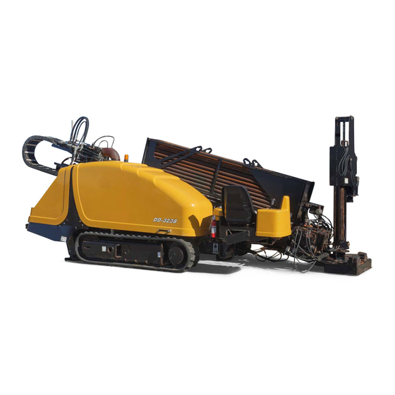
IDENTIFICATION NUMBER MACHINE COMPONENTS 3238003 1. DRILL PIPE CARRIER 4. BATTERY COMPARTMENT 7. OPERATORS SEAT 2. CONTROL PANEL 5. ENGINE COMPARTMENT 8. POWER WRENCH 3. ZAP ALERT BEACON 6. TRACK/UNDERCARRIAGE 9. STAKEDOWN PLATE/ANCHORS AU108850 D7A... -
Page 9: Safety/Decals/Hand Signals
• Background color is YELLOW. the machine before you operate or service the machine. • Prohibition symbols such as See your Astec dealer if you have any questions. STOP used are RED. READ THIS MANUAL COMPLETELY and make sure you... -
Page 10: Electric Strike Alert Safety
SAFETY • Gas Line ELECTRIC STRIKE ALERT SAFETY • Water Line • Communication Line - Telephone or Cable Television A Zap-Alert Electric Strike alarm has been installed on this machine. It is located to the left of the operator and •... -
Page 11: Gas Line Safety
SAFETY • It is likely (but not always the case) that the power Follow the instructions listed below. Failure to do so safety source interrupter or breaker will be tripped, but to be may result in serious injury or death. safe you should consider that the directional drill may •... -
Page 12: Noise Level Safety
SAFETY • Avoid loose fitting clothing, loose or uncovered long NOISE LEVEL SAFETY hair, jewelry and loose personal articles. • Operator’s station sound level is 96dB, and sound level • Do not smoke while operating or servicing this is not to exceed 104db at any position around the drill. machine. -
Page 13: Failure In Operation
Replace decals that are damaged, lost, painted serious injury. over or cannot be read. Replacement decals are available from your Astec dealer. • If shields or guards are removed or opened for service, always replace them before resuming operation of the •... -
Page 14: Battery Safety
SAFETY • Keep the area used for servicing the machine clean and • NEVER check for leaks by using any part of your body dry. Wet or oily floors are slippery. Wet spots can be to feel for escaping fluid. Keep your hands and body dangerous when working with electrical equipment. -
Page 15: Fire Or Explosion Prevention
SAFETY FIRE OR EXPLOSION FIRE EXTINGUISHER PREVENTION Fire Extinguisher A fire extinguisher of the type shown is available on your machine. This dry chemical fire extinguisher is approved Fire explosion possible. WARNING: for Class B and C type fires. Fumes could ignite and cause burns. No smoking, no flame, no spark. -
Page 16: Safety Decals
Replace any missing or damaged safety decal and keep all safety decals clean. See your Astec dealer for new safety decals. • Make sure that you read all safety and instruction decals. Check these decals every day before you start. - Page 17 SAFETY 3238012 3238021 3238013 3238010 3238011 3238014 AU108850 D7A...
- Page 18 SAFETY 3238015 3238008 3238016 3238019 3238017 3238020 AU108850 D7A...
- Page 19 SAFETY DECAL ROTATE DRILL 4. This decal is located in 2 locations by the rotating drill pipe. DECAL MOVING PARTS 3. This decal is located at 12 locations near all moving parts. 3238024 3238007 DECAL EXP HAZ 5. This decal is located in the engine compartment near the battery.
- Page 20 SAFETY 3238021 3238029 3238036 3238012 3238037 DECAL ELECT HAZ 6. This decal is located near the front and rear operator controls. AU108850 D7A...
- Page 21 SAFETY DECAL HYD COMPS 7. This decal is located at 3 locations near hydraulic components. 3238012 3238031 3238005 DECAL WARN CALL 8. This decal is located near the operators controls. DECAL DANGER CALL 9. This decal is located by the front and rear operator control panels.
- Page 22 SAFETY 3238022 3238033 HAZARDOUS AREA 11. This decal is located at 2 locations, one near the drill platform and one near the tracks. DECAL CRUSH HAZ 10. This decal is found on the drill pipe platform. 3238011 3238021 AU108850 D7A...
- Page 23 SAFETY 14. This decal is located near the drill pipe platform. TRAMMING 12. This decal is located near the rear operator’s panel. 3238034 3238028 13. This decal is located on the operator’s manual box. SPREADERBAR 15. This decal is located under the machine at the rear. 3238007 AU108850 D7A...
- Page 24 SAFETY 3238026 3238027 DECAL TIE DOWN 16. The machine tie down decals are located on each end of each track. Tie downs are not to be used for towing. IMPORTANT: AU108850 D7A...
- Page 25 CD-ROM and soft-cover book. cable/pipe layout, fabrication and testing, as-builts/ operator logs, and demobilization, site cleanup and Horizontal Astec Underground supports the restoration. Directional Drilling Good Practices Guidelines. The • Chapter 3 - Equipment & Materials following pages contain the Chapter 5 concerning Job-Site Safety.
- Page 26 SAFETY SUPPLEMENT - Horizontal Directional Drilling Good Practices Guidelines Chapter 5 CHAPTER 5 - JOBSITE SAFETY HDD safety requires essentially the same philosophy as construction. Safety must start at the management level, and every employee must be committed to the safety program if it is to be effective.
- Page 27 SAFETY SUPPLEMENT - Horizontal Directional Drilling Good Practices Guidelines Chapter 5 Develop written step-by-step procedure for performing the activity; • Eliminate, isolate or control the identified hazards with procedures; • Continuously monitor for changing hazards; • Review and revise procedures when an incident or accident occurs; •...
- Page 28 SAFETY SUPPLEMENT - Horizontal Directional Drilling Good Practices Guidelines Chapter 5 the identified hazards. As with any construction operation, compliance with all OSHA, State and Local Regulations is required, regarding general safety practices for activities including: Vehicle operation Manual lifting •...
- Page 29 SAFETY SUPPLEMENT - Horizontal Directional Drilling Good Practices Guidelines Chapter 5 Water and gas shutoff depths should be confirmed to provide initial confirmation of the • depth of the pipe and facilitate the potholing process. A minimum of 150 to 200mm (6” to 8”) should be added to depths for valves going to house services.
- Page 30 SAFETY SUPPLEMENT - Horizontal Directional Drilling Good Practices Guidelines Chapter 5 to commencement of the work. They should walk the planned borepath with the tracking equipment to evaluate any potential fields of electromagnetic (active) interference and look for signs of reinforced concrete or other possible passive interference that may hinder the operation, and discuss the identified hazards.
- Page 31 SAFETY SUPPLEMENT - Horizontal Directional Drilling Good Practices Guidelines Chapter 5 Figure 5-1. Voltage Stake of an Electrical Strike Sensing System 5.6.1 Drilling Precautions The following precautions should be observed during the drilling operation: If a hazardous situation is suspected, work should be stopped until an evaluation is made •...
- Page 32 SAFETY SUPPLEMENT - Horizontal Directional Drilling Good Practices Guidelines Chapter 5 5.6.2 Reaming and Installation Precautions The following precautions should be observed during reaming and product installation: Two-way radio communications must be maintained at all times between the entry and •...
- Page 33 SAFETY SUPPLEMENT - Horizontal Directional Drilling Good Practices Guidelines Chapter 5 5.7.4 Communications Line Strike If a communications line strike occurs, drilling must stop immediately and the utility company should be contacted. 5.7.5 Sanitary/Storm Sewer And Water Strike If a water or sewer line strike occurs, drilling should be stopped immediately and all bystanders should be warned that a strike has occurred and that they should stay away.
- Page 34 SAFETY SUPPLEMENT - Horizontal Directional Drilling Good Practices Guidelines Chapter 5 This page intentionally left blank. AU108850 D7A SS-x...
-
Page 35: Instruments And Controls
INSTRUMENTS AND CONTROLS LEFT CONTROL PANEL 3238032 EXIT SIDE LOCKOUT - OK TO DRILL LIGHT Light ON indicates that the Exit Side Transmitter is ON and the Reset Pushbutton has been pushed. It is now OK to resume drilling operations EXIT SIDE LOCKOUT - OK TO RESET Light ON indicates that the Exit Side Transmitter is ON and it is OK to reset the Exit Side Lockout System. - Page 36 INSTRUMENTS/CONTROLS EXIT SIDE LOCKOUT - BATTERY LOW Light ON indicates that the Exit Side Transmitter battery is LOW and should be changed as soon as possible. AUTODRILL SET / RESUME SWITCH Rock FORWARD to RESUME the previous autodrill speed. Rock BACKWARD to SET (turn on) Autodrill mode. You must first actuate the Carriage/Rotary Joystick to a desired speed before NOTE: setting autodrill on.
- Page 37 INSTRUMENTS/CONTROLS PIPELOADER GRIPPER Rock FORWARD to GRIP pipe. Rock BACKWARD to UNGRIP pipe. PIPELOADER TABLE Rock FORWARD to RAISE pipe table. Rock BACKWARD to LOWER pipe table. FLOOD LIGHTS SWITCH Rock FORWARD to turn ON flood lights. Rock BACKWARD to turn OFF flood lights. SETUP / DRILL SWITCH Rock FORWARD to SETUP and/or TRAVEL the drill.
-
Page 38: Right Control Panel
INSTRUMENTS/CONTROLS RIGHT CONTROL PANEL 3238040 / RIGHT-2 ENGINE RESTART PUSHBUTTON Push button IN to START / RESTART the engine. The key-switch in the rear compartment must be ON for this switch to start the engine. EMERGENCY STOP / ENGINE STOP PUSHBUTTON Push this button to STOP the drill. - Page 39 INSTRUMENTS/CONTROLS ROTARY / CARRIAGE JOYSTICK (MAKEUP DIRECTION) Move joystick LEFT to rotate pipe in MAKEUP (clockwise) direction. ROTARY / CARRIAGE JOYSTICK (BREAKOUT DIRECTION) Move joystick RIGHT to rotate pipe in BREAKOUT (counterclockwise) direction. MUD FLOW INCREASE / DECREASE SWITCH Rock FORWARD to INCREASE mud flow. Rock BACKWARD to DECREASE mud flow.
-
Page 40: Rear Control Panel
INSTRUMENTS/CONTROLS REAR CONTROL PANEL 3238039 / CTRLPNL7P ENGINE START KEY SWITCH Turn LEFT = ACC. Position = NOT USED. VERTICLE Position = STOP = Engine OFF position - Key can be removed. Turn RIGHT = Engine RUN Position - Allows engine to run. Turn HARD RIGHT = Engine START Position - Engages engine starter motor. -
Page 41: Travel Control Pendant
INSTRUMENTS/CONTROLS TRAVEL CONTROL PENDANT 3238030 TRAVEL CONTROL PENDANT - TRAVEL JOYSTICK Move joystick FORWARD to move drill FORWARD. Move joystick BACKWARD to move drill BACKWARD. Moving joystick to the RIGHT or LEFT while moving joystick forward or backward will steer the drill to the right or left respectively. -
Page 42: Life Jacket Pendant
INSTRUMENTS/CONTROLS LIFE JACKET PENDANT 3238038 LIFE JACKET PENDANT - MUD / WRENCH SWITCH Push toggle switch to LEFT to turn ON mud flow. Push toggle switch to RIGHT to ALLOW wrench (and/or pipeloader) operation. LIFE JACKET PENDANT - LEFT TRACK CONTROL SWITCH When plugged into the travel control receptacle, this switch controls the left track movement. -
Page 43: Dd-3238 Operators Display
INSTRUMENTS/CONTROLS DD-3238 OPERATORS DISPLAY 3238041 The following pages describes the multiple display pages and capabilities of the DD-3238 Operator’s Display. Full capabilities will only be accessible by a qualified service technician. NOTE: AU108850 D7A... -
Page 44: System Boot Screen
INSTRUMENTS/CONTROLS SYSTEM BOOT SCREEN 3238042 • Screen only active during initial start-up. • Screen will display whenever ESC key is activated on first three pages of the display. • No hotkeys are active when this page activates. AU108850 D7A... -
Page 45: Main Operating Screen
INSTRUMENTS/CONTROLS MAIN OPERATING SCREEN 3238043 • Screen displays automatically after boot screen has finished. • Screen displays engine rpm on upper left gauge and temperature on upper right gauge. • Additional information is available as indicator lights for the following items: A. -
Page 46: Drill Operating Screen
INSTRUMENTS/CONTROLS DRILL OPERATING SCREEN 3238044 • Screen is accessed from the Main Operating screen by pressing the down arrow on display. • Screen displays rotary and carriage pressure as well as current mud flow rate. • The following additional information is available as an indicator light: A. -
Page 47: Drill Force Screen
INSTRUMENTS/CONTROLS DRILL FORCE SCREEN 3238045 • Screen accessed from the Drill Operating screen by pressing the down arrow on display, or from the Main Operating screen pressing the down arrow twice. • Screen displays approximate rotary and carriage forces. Mud flow rate is also displayed. NOTE: Carriage forces apply only to carriage low speed. -
Page 48: Additional Information Screen
INSTRUMENTS/CONTROLS ADDITIONAL INFORMATION SCREEN 3238046 • Screen is accessed from the Drill Force screen by pressing the down arrow on display, or from the Drill Operating screen pressing the down arrow twice, or from the Main Operating screen pressing the down arrow three times. •... -
Page 49: Machine Information Screen
INSTRUMENTS/CONTROLS MACHINE INFORMATION SCREEN 3238047 • Screen displays serial number, engine hours and the total number of mud gallons the mud pump has produced as well as a resettable number of mud gallons the mud pump has produced this job. •... -
Page 50: General System Help Screen
INSTRUMENTS/CONTROLS GENERAL SYSTEM HELP SCREEN 3238048 • This screen provides a message stating what the display is meant to be used for and to remind the operator to read the Owner’s Manual. • Pressing the number 4 pushbutton switch will return back to the Drill Force screen. AU108850 D7A... -
Page 51: Read Error Codes Screen
INSTRUMENTS/CONTROLS READ ERROR CODES SCREEN 3238049 • This screen displays the number of active alarms. • If no alarms are active, the message “NO ERROR CODES!” is displayed. • When more than one code is active, the up and down arrow keys will allow you to scroll through the active codes. •... -
Page 52: Diagnose And Update Screen
INSTRUMENTS/CONTROLS DIAGNOSE AND UPDATE SCREEN 3238050 • An 8-digit alpha-numeric password must be entered to gain access to pages beyond this point. Only qualified technicians should access information beyond this screen. • Incorrect passwords entered will generate an error message on the screen. •... -
Page 53: Error Code Descriptions
INSTRUMENTS/CONTROLS ERROR CODE DESCRIPTIONS CODE DESCRIPTION EXPLANATION A101 Auxiliary Error Auxiliary output out of normal range. TR01 Right Reverse Error Right trackdrive out of range in reverse direction. TL01 Left Reverse Error Left trackdrive out of range in reverse direction. TR02 Right Forward Error Right trackdrive out of range in forward direction. -
Page 54: Operators Seat And Platform
INSTRUMENTS/CONTROLS OPERATORS SEAT AND PLATFORM 3238052 To raise the hood, disconnect the hood latch (1) near the operators platform and carefully raise the hood. To lower and lock the hood, slowly lower the hood and connect the hood latch to the frame. The radiator access hood (2) at the rear of the machine works in the same manner. -
Page 55: Operating Instructions
If you come across any problems during testing contact reset the Zap-Alert Alarm until the utility company your dealer or Astec Underground immediately. has been contacted and power to the line has been Do not start drilling until proper operation of Zap- disconnected. -
Page 56: Es!Lok® Machine Lockout System
OPERATING INSTRUCTIONS es!lok® MACHINE LOCKOUT INSTALLATION/CONFIGURATIION SYSTEM T50 TRANSMITTER R130E RECEIVER The es!lok Machine Lockout System gives the personnel working around the rotating drill pipe a means to disable System Overview the Rotation and Thrust of the machine. The es!lok system consists of a receiver mounted on the drill and a This system is a portable, long range, programmable transmitter that is carried by a designated person working... - Page 57 OPERATING INSTRUCTIONS R130 Receiver T50 Dimensions and Controls R130 RECEIVER T50 Transmitter T50 DIMS & CTRLS R130 Dimensions T50 TRANSMITTER R130 DIMS Power The T50 Transmitter 1. Install batteries. Remove the battery cover on the b a c k o f t h e T 5 0 t ra n s m i t t e r u s i n g a s l o t t e d screwdriver and insert 4 “AA”...
- Page 58 OPERATING INSTRUCTIONS Test The Transmitter/Receiver Link Download ID Code (Use if Link Test Fails) The T50 transmitter has a built-in “time out” feature. If Follow these steps to download the transmitter’s unique the transmitter remains inactive for 4 hours, the ID Code into the receiver.
-
Page 59: Specifications R130 Receiver/T50 Transmitter
OPERATING INSTRUCTIONS 4. Put the R130 receiver into Setup Mode. T50 SEND CODE 5. Press GREEN ON button to send code. Once the ID Code has been downloaded, the RED (Battery) light and the YELLOW (Active) light on the R130 SETUP MODE A transmitter will go out. -
Page 60: Diagnostics - T50 Transmitter
OPERATING INSTRUCTIONS DIAGNOSTICS - T50 TRANSMITTER T50 DIAG LIGHTS LIGHT LEGEND 1 AU108850 D7A... - Page 61 OPERATING INSTRUCTIONS Normal Operation NORMAL LIGHTS Trouble Indicators In some cases, the indicator lights will be different depending on whether the transmitter is on or off. Please NOTE: note the transmitter status in the “Description” column for each case. DIAG LIGHTS AU108850 D7A...
- Page 62 OPERATING INSTRUCTIONS Test The Receiver - R130 (Chart #1) R130 FLOW 1 AU108850 D7A...
- Page 63 OPERATING INSTRUCTIONS Test The Receiver - R130 (Chart #2) T50 FLOW 1 AU108850 D7A...
- Page 64 OPERATING INSTRUCTIONS Testing The Transmitter / Receiver Communication (Chart #3) LINK CHART 1 AU108850 D7A...
-
Page 65: Understanding Directional Drilling
OPERATING INSTRUCTIONS UNDERSTANDING DIRECTIONAL DRILLING Proper Drilling Method There are also special soil conditions at various depths. These may include shale, rock and hard packed clay. Directional drilling is a process of drilling a pilot hole, then Small stone or gravel may also be in various layers of soil. making the diameter larger with a back reamer as it is In such conditions, it may be necessary to pull back the pulled back through the pilot hole. - Page 66 Soft soils require a larger drill head blade. Harder soils require a smaller drill head blade. See your authorized Astec Underground dealer for our particular application requirements. AU108850 D7A...
-
Page 67: Hole Length/Depth Chart
OPERATING INSTRUCTIONS HOLE LENGTH / DEPTH BENDCHARTA Drilling Obstructions The operator must decide whether to excavate a small hole to determine the size of the obstruction or to Many obstructions exist underground. The drill head will continue drilling with increased fluid flow to let the system run into rocks, boulders, old foundations, old road beds, drill its way through the obstruction. -
Page 68: Drill Tracking Electronics
Electronic tracking equipment and accessories are bending stress on the connections. For this reason rotate available from your Astec Underground dealer directly. the order in which you use the pipes. DO NOT use the same pipe to start every bore. The first pipe is The tracking system includes three components - the usually subjected to the highest stress. -
Page 69: Engine Operation
Some transmitters have an alarm to signal when the temperature limit is about to be Before Starting Engine exceeded. For additional information see your authorized Astec Underground dealer. : Before starting engine, study WARNING operator’s manual safety messages. Read all Depth of Bore safety signs on machine. -
Page 70: Run-In Maintenance Schedule
Cold Temperature Starting Aids OPERATING IN COLD WEATHER See your Astec Underground dealer for extra starting Cold weather conditions cause special problems. During accessories such as: battery heater, engine oil heater, etc. these conditions your machine will require special Cold Weather Parking attention to prevent serious damage. -
Page 71: Starting The Engine
OPERATING INSTRUCTIONS STARTING THE ENGINE BOOSTER BATTERY CONNECTIONS Before starting engine, study WARNING: Batteries contain acid WARNING: operator’s manual safety messages. Read all explosive gas. Explosion can result from sparks, safety signs on machine. Clear the area of other flames or wrong cable connections. To connect persons. -
Page 72: Parking And Stopping The Engine
OPERATING INSTRUCTIONS PARKING AND STOPPING THE MACHINE OPERATION ENGINE WARNING: Before each period of operation, 1. When the work day is finished, make sure the check the machine for correct operation of the machine is parked on level ground. The machine must steering, hydraulic controls, instruments, and b e o n l e ve l g ro u n d b e fo re yo u d o s c h e d u l e d safety equipment. -
Page 73: Transporting The Machine
OPERATING INSTRUCTIONS IMPORTANT: Use a low engine throttle speed for Walk the machine in the FORWARD WARNING: maneuvering the machine onto the trailer or truck. direction for added safety precaution and easier 3. Be careful, walk the machine slowly onto the trailer maneuvering when on level ground or going or truck bed. -
Page 74: Electronic Tracking System
“true” path signal from the ghost signals. For additional information be sure to read your tracker and receiver’s Owner’s Manual. Contact your authorized Astec Underground dealer for additional information. SPREADER To lift the machine onto a trailer or truck, attach a crane lift cable to the single lift point of a spreader bar. -
Page 75: Zap Alert Strobe
OPERATING INSTRUCTIONS ZAP ALERT STROBE DRILL DIAGRAM 1. Locate machine so first pipe can be drilled straight to 3238003 reach the required depth. Before operating your machine, make sure the ZAP Alert Strobe beacon lamp is on and working. 2. Thrust Frame. 3. -
Page 76: Power Stakedown
OPERATING INSTRUCTIONS POWER STAKEDOWN Power anchor can move if lever is WARNING: activated, even if engine is not running. Auger can slip and cause serious injury. Always keep hands and feet away from auger flighting and auger pockets. Rotating parts - keep clear of WARNING: hazardous area. -
Page 77: Pipe Loader Operation
OPERATING INSTRUCTIONS 2. Pipe carrier must be unlocked from Directional Drill. To unlock, remove pipe carrier lock pins (2) from both the front and rear of the pipe carrier. 3. Remove carrier from Directional Drill. 4. Install new pipe carrier in position on the Directional Drill. -
Page 78: Accessories And Optional Equipment
9. Rotate drive chuck CLOCKWISE and move carriage Drill pipes are available in various diameters and styles for forward slowly. different job requirements. See your authorized Astec 10. Make up joint until specified torque is reached. Underground dealer for more information. -
Page 79: Operational Hookup Connection
OPERATING INSTRUCTIONS 6. Mix your drilling fluid for your drilling operation. 7. Machine is ready to start drilling operation. Operate this machine only when all WARNING: Setting Engine Speed persons are safely clear of moving parts and the machine. Set the engine speed at high idle using the throttle control. -
Page 80: Pilot Bore Operation
OPERATING INSTRUCTIONS PILOT BORE OPERATION Adding Drill Pipes Thrust drill pipes into the ground until the drill drive 1. Position the lead bar, or previous drill pipe in the gearbox reaches the front stop. Then move the gearbox lower wrench so the threaded pipe end is positioned REARWARD to pull the drill pipe back approximately 1/4 behind the jaws. -
Page 81: Horizontal Reach Boring
See Drill Tracking Much like drill head blades, different soil conditions Electronics in this manual. require different reamers. See your authorized Astec Some transmitters are equipped with an alarm to give Underground dealer for more information. - Page 82 7. Clamp upper wrench clamp. caused by various drilling lubricants and fluids such as Bentonite and polymers. See your authorized Astec 8. Rotate upper wrench clamp COUNTERCLOCKWISE Underground dealer for more information.
-
Page 83: Pressure Washing The Machine
OPERATING INSTRUCTIONS Removing Drill Pipes UNLOADING DRILL PIPE DURING BACK REAM / PULL BACK NEVER guide or hold drill pipe with WARNING: IMPORTANT: Make sure the loader arms are completely your hands or feet. ALWAYS keep feet on retracted and drill pipe is unthreaded from the pipe operators platform and hands on controls. - Page 84 OPERATING INSTRUCTIONS NOTES AU108850 D7A...
-
Page 85: Lubrication
Chart to service your machine at the correct time periods. PIC00056 Before you service the machine, put a Do Not Operate tag on the control panel. This tag, Astec part number AU103157 is available from your dealer. The Do Not Operate tag is included with your machine. -
Page 86: Capacities And Lubricant Specifications
Type of Lubricant .......................SAE 30-CD (AU-403) MUD PUMP L09 Capacity ........................... 2.84 L (3 U.S. Qt) Specification ....................Astec ISO100 Gear Lubricant (AU-103) MUD PUMP L06 Capacity ........................... 1.89 L (2 U.S. Qt) Specification ....................Astec ISO100 Gear Lubricant (AU-103) RADIATOR Capacity .......................... -
Page 87: Lubrication/Maintenance Chart
LUBRICATION LUBRICATION/MAINTENANCE CHART Daily/10 Hrs Weekly/50 Hrs Monthly/250 Hrs 6 Months/500 Hrs Yearly/1000 Hrs Check Engine Crankcase Oil Check Engine Coolant Level Check Hydraulic Oil Level Check Fuel Level Check Mud Pump Crankcase Oil Rotary Box Oil Level Inspect For Leaks Grease Check Track Tension Carriage Planetary Gearbox Oil... -
Page 88: Oil Viscosity/Temperature Usage Chart
LUBRICATION Engine Oil Selection Astec Engine Oil is recommended for use in your engine. Astec Engine Oil will lubricate your engine correctly under all operating conditions If Astec Multi-Viscosity is not available, use only oil meeting API engine oil service category CD. -
Page 89: Engine Oil
LUBRICATION ENGINE OIL Engine Oil and Filter Change Change the engine oil and engine oil filter every NOTE: Check the engine oil every 10 hours of operation NOTE: 250 hours of operation or once every month, whichever or once every day, whichever occurs first. occurs first. -
Page 90: Air Filtering System
LUBRICATION 10. Refill the crankcase with the specified amount of Dust Valve recommended oil through the oil filler cap (2). 11. Install the oil filler cap. 12. Start the engine. Run the engine at idle for approximately 2 minutes. Check for oil leaks. 13. -
Page 91: Fuel System
LUBRICATION 4. Clean or replace the filter element. See Cleaning the 10. Install the filter element, being sure to engage with Element in this manual. housing. The date of manufacture is on the end of the Apply a thin coat of talcum or baby powder to the NOTE: NOTE: element. - Page 92 Fuel Conditioner 4. Open the water drain at the bottom of the fuel filter. Diesel Fuel Conditioner is available from your Astec dealer. Close the drain after all water has been removed. Instructions for the use of the Diesel Fuel Conditioner are...
-
Page 93: Hydraulic Oil System
LUBRICATION 7. Install the filter by hand turning the filter clockwise. HYDRAULIC OIL SYSTEM Hand tighten the filter 1/2 turn after the filter makes contact with the filter head. DO NOT use a filter wrench to install filter. NOTE: Fluid under pressure can pierce WARNING: Damage to the filter may occur. -
Page 94: Engine Cooling System
LUBRICATION 4. If you must add oil to the hydraulic reservoir, clean Replace all covers or guards after WARNING: the area around the filler cap (2), and remove from servicing or cleaning the machine. NEVER the filler tube. Add oil and reinstall filler cap. See operate the machine with covers or guards LUBRICANT SPECIFICATIONS in this manual for the removed... - Page 95 LUBRICATION A mixture of 50% Ethylene Glycol and 50% water is used in this machine. This mixture is used if the lowest ambient temperature is above -37°C (-34°F). It is recommended that Ethylene Glycol and water be used in your machine all year.
-
Page 96: Track Planetary Drive
LUBRICATION TRACK PLANETARY DRIVE Track Planetary Drive Oil Level Check the oil level of each planetary track drive every 10 hours of operation. Park the machine on a level surface. 3238080 2. Place a suitable sized container under radiator. Remove the radiator drain plug (2). 3. -
Page 97: Drill Fluid Pump Oil Level
LUBRICATION 3238078 2. To check level, look at the site gauge (1). If low, add oil. Do not overfill the crankcase. 3. When service is complete, install and tighten plug. 3238090 To change the planetary oil: Cold Weather Protection 1. Move the machine to put the track planetary oil fill/ When the outside temperature reaches 0°C (32°F) or level plug (1) at the 12 o’clock position with the drain lower, it is necessary to prepare the water pump to... -
Page 98: Rotary Drive Gearbox
LUBRICATION ROTARY DRIVE GEARBOX Oil Level Check the rotary drive gearbox oil level every 50 hours of operation or once each week. Remove oil level plug. Check oil level. Add gear oil if necessary. Install and tighten level plug. NOTE: See Lubricants in this manual for the planetary track drive oil specifications. -
Page 99: Adjustment/Maintenance
ADJUSTMENT/MAINTENANCE FASTENER INSPECTION TRACK TENSION AND ADJUSTMENT Only make track tension adjustment when track is Check all major fasteners, such as hose clamps, NOTE: stakedown, tie downs, etc. Tighten all loose fasteners. too loose or too tight. Track tension must always be correct. -
Page 100: Hydraulic Hoses And Fittings Inspection
ADJUSTMENT/MAINTENANCE HYDRAULIC HOSES AND FITTINGS If threads are worn or damaged, the connection between the drill pipe and spindle adapter will not be properly INSPECTION secured. Check the hydraulic hoses and fittings for leaks and/or Using a worn or damaged spindle saver sub will NOTE: damage. -
Page 101: Electrical
Do not use a steam cleaner or cleaning solvent to clean battery. Use one of the following methods to clean the the alternator. battery. 1. Use Astec Battery Saver, Astec part number REN280. Follow the instructions on the container. This cleaner does not need water. AU108850 D7A... - Page 102 ELECTRICAL 2. Use baking soda or ammonia and flush the outside of the battery with water. If you do not have Astec Battery Saver, use other special cleaners to prevent corrosion on the battery terminals. Battery Recycling Discarding old batteries can cause an environmental liability.
-
Page 103: Machine Storage
3. Paint any areas where the paint has been damaged. 5. Lubricate the machine at all grease fittings. 4. Change the engine oil and oil filters. 6. Remove the Astec Rust and Corrosion Preventative from the hydraulic cylinder rods and control valve 5. Drain the fuel tank. - Page 104 MACHINE STORAGE NOTES AU108850 D7A...
-
Page 105: Specifications
SPECIFICATIONS BASIC MACHINE DIMENSIONS Length............................614.7 cm (242 in) Width ............................226.1 cm (89 in) Ground Clearance......................... 30.48 cm (12 in) Approximately Operating Weight....................8,047 kg (17,740 lbs) ENGINE DATA Make and Model ......................John Deere® 4045T Diesel Rating ............................93.2 kW (125 hp) Fuel Capacity ........................... -
Page 106: Torque Specifications
SPECIFICATIONS TORQUE SPECIFICATIONS - DECIMAL HARDWARE Use the torques in this chart when special torques are not Grade 8 Bolts, Nuts, and Studs given. These torques apply to fasteners with both UNC and UNF threads as received from suppliers dry, or when lubricated with engine oil. - Page 107 SPECIFICATIONS TORQUE SPECIFICATIONS - METRIC HARDWARE Use the following torques when specifications are not Grade 10.9 Bolts, Nuts, and Studs given. These values apply to fasteners with both coarse and fine 10.9 threads as received from supplier, plated or unplated, or when lubricated with engine oil.
- Page 108 SPECIFICATIONS TORQUE SPECIFICATIONS - STEEL HYDRAULIC FITTINGS 37 Degree Flare Fitting Nom. SAE Dash Size Tube OD/Hose ID Thread Size Newton metres Pound-Inches 5/16 - 24 8 to 9 72 to 84 3/8 - 24 11 to 12 96 to 108 6.4 mm (1/4 inch) 7/16 - 20 14 to 16...
- Page 109 SPECIFICATIONS Split Flange Mounting Bolts Size Newton metres Pound-Inches 5/16-18 20 to 27 180 to 240 3/8-16 27 to 34 240 to 300 7/16-14 47 to 61 420 to 540 Pound-Feet 1/2-13 74 to 88 55 to 65 5/8-11 190 to 203 140 to 150 O-Ring Boss End Fitting or Lock Nut...
- Page 110 SPECIFICATIONS Pipe fittings Nom. SAE Dash Size Thread Size TFFT (Turns For Finger Tight) 1/8 - 27 2.0 - 3.0 1/8 - 27 2.0 - 3.0 1/8 - 27 2.0 - 3.0 1/8 - 27 2.0 - 3.0 1/4 - 18 1.5 - 3.0 3/8 - 18 2.0 - 3.0...
-
Page 111: Index
INDEX DO NOT OPERATE Tag ........9, 71 Downloading ID Code ..........44 Adding Drill Pipes ........... 66 Drill Angle .............. 91 Additional Information Screen ......... 34 Drill Drive Spindle Saver Sub ........86 After Delivery Check ......... 56, B1 Drill Fluid Pump Cold Weather Protection .... - Page 112 INDEX Engine Cooling System ........... 80 FHSS Technology ........... 42 Engine Make and Model .......... 91 Fiber Optic Cable ............7 Engine Oil Change ..........75 Fire Extinguisher ............ 86 Engine Oil Filter Change .......... 75 Fire Extinguisher Inspection and Care ...... 86 Engine Oil Selection ..........
- Page 113 INDEX Pipeloader Table ..........23 Mud Flow Capacity ..........91 Rotary Pipe Clamp ..........22 Mud Pump Output ..........91 Setup/Drill Switch ..........23 Stationary Pipe Clamp .........22 Noise Level Safety ............ 8 Length ..............91 Nozzle Wear ............68 Life Jacket Pendant ..........28 Carriage Control Switch ........28 Left Track Control Switch ........28 Oil Change .............
- Page 114 INDEX Removing Air from Fuel System ....... 79 T50 Trouble Indicators ........... 47 Removing Drill Pipes ..........69 Test the Receiver - Chart 1 ........48 Removing Machine from Storage ......89 Test the Receiver - Chart 2 ........49 Right Control Panel ..........
- Page 115 AFTER DELIVERY CHECK AFTER DELIVERY CHECK After First 50 Hours of Operation of New Machine Date of Check________________Hourmeter Reading__________________________________________ hours MACHINE: Product Identification Number ________________________________________________________ OWNER: Name ______________________________________________________________________________ Address ______________________________________________________________________________ DEALER:Name ______________________________________________________________________________ Address ______________________________________________________________________________ TRACK PLANETARY HYDRAULIC SYSTEM Check track planetary oil level. Change the hydraulic filters.
- Page 116 AFTER DELIVERY CHECK NOTES AU108850 D7A...
- Page 117 AFTER DELIVERY CHECK AFTER DELIVERY CHECK After First 50 Hours of Operation of New Machine Date of Check________________Hourmeter Reading__________________________________________ hours MACHINE: Product Identification Number ________________________________________________________ OWNER: Name ______________________________________________________________________________ Address ______________________________________________________________________________ DEALER:Name ______________________________________________________________________________ Address ______________________________________________________________________________ TRACK PLANETARY HYDRAULIC SYSTEM Check track planetary oil level. Change the hydraulic filters.
- Page 118 AFTER DELIVERY CHECK NOTES AU108850 D7A...
- Page 119 State of California to cause cancer, birth defects, and other reproductive harm. Astec reserves the right to make improvements in design or changes in specifications at any time without incurring any obligation to install them on units previously sold. AU108850 D7A...
- Page 120 AFTER DELIVERY CHECK NOTES AU108850 D7A...
Need help?
Do you have a question about the EarthPro DD-3238 and is the answer not in the manual?
Questions and answers