
Related Manuals for SNBC BT-T080R


Summary of Contents for SNBC BT-T080R
- Page 1 User’s Manual Embedded Printer BT-T080R Shandong New Beiyang Information Technology Co., ltd.
- Page 2 If users need further data about this product, please feel free to contact SNBC or your local dealer. No part of this document may be reproduced or transmitted in any form or by any means, electronic or mechanical, for any purpose without the express written permission of SNBC.
- Page 3 BT-T080R User’s Manual Safety Instructions Before installing and using the printer, please read the following items carefully: 1. Safety warnings Warning: Do not touch the cutter and tear-off bar of printer. Warning: The print head is a thermal element and it is at a high temperature during printing or just after operation, therefore do not touch it or its peripherals for reasons of safety.
-
Page 4: Table Of Contents
BT-T080R User’s Manual Contents 1 Outline ................................. 1 1.1 Brief introduction ..........................1 1.2 Main features............................1 2 Main technical index ............................ 2 2.1 Technical specifications........................2 2.2 Cutter technical parameters ........................ 3 2.3 Status detection........................... 4 2.4 Print paper technical index ........................5 2.4.1 Continuous paper parameter ...................... - Page 5 BT-T080R User’s Manual 4.3.1 Cantilever angle: 0°........................16 4.3.2 Cantilever angle: 30°........................18 4.3.3 Cantilever angle: 60°........................19 4.3.4 Cantilever angle: 90°........................21 4.3.5 Cantilever angle: -30° ......................... 23 4.3.6 Cantilever angle: -60° ......................... 25 4.3.7 Installing the paper roll baffle ...................... 27 4.4 Installing and adjusting paper near end sensor .................
- Page 6 BT-T080R User’s Manual 6.3 Power interface ..........................43 7 Troubleshooting ............................44 7.1 Common errors and settlement ......................44 7.2 Solutions for common errors ......................46 Appendix............................... 48 Appendix 1 Self-test page ........................48 Appendix 2 Software tool......................... 50 - 5 -...
-
Page 7: Outline
BT-T080R User’s Manual 1 Outline 1.1 Brief introduction BT-T080R printer is a high performance thermal printer with high adaptability and strong adjustability. It can be widely used in various circumstances that need real-time printing on the spot, like financing, telecommunication, etc. -
Page 8: Main Technical Index
BT-T080R User’s Manual 2 Main technical index 2.1 Technical specifications Item Parameter (203dpi) Print method Thermal printing Resolution 203DPI Paper width 48~82.5±0.5 mm Max. 80mm (3.2″) Print width Max. 640 dots Print height Max.: 480 mm, Min.: 5 mm Print speed... -
Page 9: Cutter Technical Parameters
BT-T080R User’s Manual Item Parameter (203dpi) MTBF (main control 360,000 hours board) MTBF (printer) 5000 hours Operation environment 0~50℃, 20~90%RH (40 ) ℃ Environment Storage environment -40~60℃, 20~93% RH (40 ) ℃ Overall size 100(L) X 157(W) X 123(H) (printer mechanism) -
Page 10: Status Detection
BT-T080R User’s Manual 2.3 Status detection Detecting content Sensor type Mechanical photoelectric Paper status sensor Mark Photoelectric sensor Print head position Microswitch Print head temperature Thermal resistor Table 2.3 Status detection Figure 2.3.1 Mark sensor 1 Figure 2.3.2 Mark sensor 2 Note: When the mark sensor is located in position A, the mark is located in non-thermal layer;... -
Page 11: Print Paper Technical Index
BT-T080R User’s Manual 2.4 Print paper technical index Figure 2.4.1 Paper roll with thermal layer outward Paper roll with thermal layer inward 2.4.1 Continuous paper parameter Item Parameter Remark Paper width 48~82.5mm Recommended: 70~82.5mm Paper thickness 60~100μm Paper roll OD ≤180mm... -
Page 12: Recommended Paper
BT-T080R User’s Manual position 4 (three positions). Ensure the midlines of mark and paper coincide; Mark position 4 can only be located in non-thermal layer. In using marks, it is recommended to use the following parameters: L1 mark width: 8mm≤L1≤paper width L2 mark height: 4mm≤L2≤8mm... - Page 13 BT-T080R User’s Manual When the temperature goes up to 70 degrees, paper will discolor. So please be careful to the effect of temperature, humidity and sunlight in environment. - 7 -...
-
Page 14: Print And Cut Position
Note: The path width of BT-T080R is wider than that of paper. While the paper is moving in the path, there is some movement in the horizontal direction. In this way, there is some tolerance for print position in the horizontal direction, which is normal and does not have an effect on using. -
Page 15: Appearance And Modules
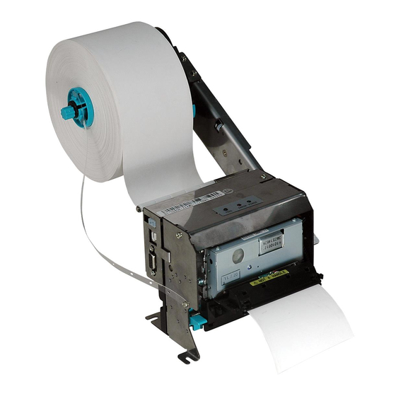
BT-T080R User’s Manual 3 Appearance and modules 3.1 Appearance and modules Figure 3.1.1 BT-T080R printer 1. Print mechanism module 2. Cantilever paper shaft module Figure 3.1.2 Print mechanism module 3. Button and LED 4. Mechanism spanner 5. Cutter 6. Tear-off bar 7. - Page 16 BT-T080R User’s Manual Figure 3.1.4 Print mechanism module (with paper outlet module) 10. Communication interface: parallel interface (optional) 12. Paper out module: paper outlet (with LED) (optional) Figure 3.1.5 Cantilever module 13. Cantilever 14. Buffer shaft 15.Paper roll shaft 16. Paper roll guide 17.
-
Page 17: Overall Size Of Printer
BT-T080R User’s Manual 3.2 Overall size of printer 3.2.1 Without paper outlet module Figure 3.2.1 Overall size of printer without paper out module 3.2.2 With paper outlet module (optional) Figure 3.2.2 Overall size of printer with paper outlet module 3.2.3 With anti-pull and anti-jam module Figure 3.2.3 Overall size of printer with anti-pull and anti-jam module... -
Page 18: Button And Led
BT-T080R User’s Manual 3.3 Button and LED Figure 3.3.1 Button and LED Button function explanation: Button Function Description Printer feeds paper after FEED this button is pressed FEED button down. LED status explanation: Status Description The printer is abnormal. /... -
Page 19: Anti-Pull And Anti-Jam Module (Optional)
BT-T080R User’s Manual 3.5 Anti-pull and anti-jam module (optional) Figure 3.5.1 Print mechanism module (with anti-pull and anti-jam module) 1. Anti-pull and anti-jam module 2. Alarm label Figure 3.5.2 Alarm label Module function explanation: When there is paper jam in the paper outlet, the module works and stops feeding paper to avoid influencing user’s use and mechanism lifetime caused by mechanism paper jams. -
Page 20: Installing The Printer
BT-T080R User’s Manual 4 Installing the printer 4.1 Unpacking Open the carton and check whether all items listed on the package list are included or have any damages. In case of damages or missing items, please contact your dealer or the manufacture for assistance. -
Page 21: Installing And Fixing Print Mechanism
BT-T080R User’s Manual 4.2.2 Installing and fixing print mechanism There are holes for fixing on BT-T080R printer mechanism holder, so the holder can be connected with the customer’s printer reliably and conveniently. The printer should be placed horizontally. Figure 4.2.2 Size of print mechanism installation Note: Recommend using M4×8 pan head screw for fixing. -
Page 22: Installing Cantilever Module (Including The Installation Of The Buffer Module
BT-T080R User’s Manual 4.3 Installing cantilever module (including the installation of the buffer module) There are six positions for installing the cantilever paper shaft module on the mechanism module, and fix the cantilever paper shaft module onto the mechanism module using three randomly promotional screws. - Page 23 BT-T080R User’s Manual 1)Paper roll with thermal layer outward Figure 4.3.3 Module installation setting and size Position 1 for installing buffer Buffer shaft position 1 2)Paper roll with thermal layer inward Figure 4.3.4 Module installation setting and size Position 2 for installing buffer...
-
Page 24: Cantilever Angle: 30
BT-T080R User’s Manual 4.3.2 Cantilever angle: 30° The cantilever angle is 30°, that is, the intersection angle between the cantilever and the horizon is 30°.The following drawing indicates the relative position of the print mechanism to fixing holes marked by solid circle and the extreme size after installing the paper roll. -
Page 25: Cantilever Angle: 60
BT-T080R User’s Manual 2)Paper roll with thermal layer inward Figure 4.3.7 Module installation setting and size Position 2 for installing buffer Buffer shaft position 2 4.3.3 Cantilever angle: 60° The cantilever angle is 60°, that is, the intersection angle between the cantilever and the horizon is 60°.The following drawing indicates the relative position of the print mechanism to fixing holes marked by solid circle and the extreme size after installing the paper roll. - Page 26 BT-T080R User’s Manual 1)Paper roll with thermal layer outward Figure 4.3.9 Module installation setting and size Position 1 for installing buffer Buffer shaft position 1 2)Paper roll with thermal layer inward Figure 4.3.10 Module installation setting and size - 20 -...
-
Page 27: Cantilever Angle: 90
BT-T080R User’s Manual Position 2 for installing buffer Buffer shaft position 2 4.3.4 Cantilever angle: 90° The cantilever angle is 90°, that is, the intersection angle between the cantilever and the horizon is 90°.The following drawing indicates the relative position of the print mechanism to fixing holes marked by solid circle and the extreme size after installing the paper roll. - Page 28 BT-T080R User’s Manual Figure 4.3.12 Module installation setting and size Position 1 for installing buffer Buffer shaft position 1 2)Paper roll with thermal layer inward - 22 -...
-
Page 29: Cantilever Angle: -30
BT-T080R User’s Manual Figure 4.3.13 Module installation setting and size Position 2 for installing buffer Buffer shaft position 2 4.3.5 Cantilever angle: -30° The cantilever angle is -30°, that is, the cantilever is located below the print mechanism and the intersection angle between the cantilever and the horizon is 30°.The following drawing indicates the... - Page 30 BT-T080R User’s Manual Figure 4.3.14 Installation position with the cantilever angle -30° 1)Paper roll with thermal layer outward Figure 4.3.15 Module installation setting and size Position 1 for installing buffer Buffer shaft position 1 - 24 -...
-
Page 31: Cantilever Angle: -60
BT-T080R User’s Manual 2)Paper roll with thermal layer inward Figure 4.3.16 Module installation setting and size Position 3 for installing buffer Buffer shaft position 2 4.3.6 Cantilever angle: -60° The cantilever angle is -60°, that is, the cantilever is located below the print mechanism and the intersection angle between the cantilever and the horizon is 60°.The following drawing indicates the... - Page 32 BT-T080R User’s Manual Figure 4.3.18 Module installation setting and size Position 2 for installing buffer Buffer shaft position 1 2)Paper roll with thermal layer inward Figure 4.3.19 Module installation setting and size - 26 -...
-
Page 33: Installing The Paper Roll Baffle
BT-T080R User’s Manual Position 3 for installing buffer Buffer shaft position 2 4.3.7 Installing the paper roll baffle 1)Refer to the following figure, install the paper roll baffle onto the baffle connection film. Figure 4.3.20 Installing the paper roll baffle 1. -
Page 34: Installing And Adjusting Paper Near End Sensor
BT-T080R User’s Manual 4.4 Installing and adjusting paper near end sensor 4.4.1 Installing paper near end sensor Refer to the following figure, plug the paper near end sensor into the outward paper near end sensor socket after installing the cantilever module on print mechanism. - Page 35 BT-T080R User’s Manual The minimum remaining paper of different specifications detected by different levels of paper near end sensor is as follows (theoretical value): Paper thickness Level 1 Level 2 Level 3 Level 4 Level 5 (μm) Remaining paper 29.8m 31.6m...
-
Page 36: Connecting The Ac Power Adapter
BT-T080R User’s Manual 90μm 10.3m 19.6m 100μm 9.3m 17.6m Remaining paper 74.2m 81.8m roll diameter 60μm 30.5m Paper roll core ID φ60mm 70μm 12.9m 26.2m Paper roll core OD Remaining paper 80μm 11.3m 22.9m φ66mm length 90μm 20.4m 100μm 18.3m Table 4.4.2 Minimum remaining paper detected by paper near end sensor... -
Page 37: Connecting Interface Cable
BT-T080R User’s Manual 4.6 Connecting interface cable Make sure that the printer has been shut down; Connect the USB cable into the relevant interface of printer, (see Figure 4.6.1); Connect the other end of the interface cable to the host computer. -
Page 38: Installing And Loading Paper Roll
BT-T080R User’s Manual 4.7 Installing and loading paper roll Before installing the paper roll, please install the cantilever paper holder first according to the requirements of 4.3 and 4.4 and set position for relevant paper near end sensor, making sure the specification of paper roll is in conformity with the printer’s requirements (Detailed requirements please refer to 2.3.). - Page 39 BT-T080R User’s Manual Figure 4.7.4 Adjusting paper roll guide Remove the paper roll baffle, and install the paper roll onto the paper roll shaft to make one end face of the paper roll contact with the paper roll guide; Figure 4.7.5 Install the paper roll onto the paper roll shaft Install the paper roll baffle onto the paper roll shaft and fix the position of the paper roll.
-
Page 40: Loading Paper
BT-T080R User’s Manual space; After installing the paper roll baffle, rotate the paper roll and make sure the paper roll can rotate smoothly. While fixing paper guide locking screw, please don’t use too much force to avoid the damage of parts. - Page 41 BT-T080R User’s Manual Figure 4.7.10 Paper passes by the buffer shaft while loading paper Push the paper into the paper inlet for a certain distance along the arrow direction. When the print roller starts rotating and holding paper, release both hands. Ensure that the position of the paper’s thermal side is as shown in the following figure.
-
Page 42: Installing The Driver
BT-T080R User’s Manual 4.8 Installing the driver BT-T080R printer offers driver for the operation systems such as Windows 2000/ Windows XP/ Windows server 2003/Windows Vista/Windows Server 2008/Windows 7. Its current Chinese installation package is Setup_BT-T080R_CN V1.0, and the installation includes typical installation and advanced installation. - Page 43 BT-T080R User’s Manual Select the Setup Type “Typical” and then click “Next” button; The driver identifies the current system type automatically, and then click “Next” button; Set printer port, and select ”USB_BT-T080R_1” as the print port. Then click “Install” to end the installation.
-
Page 44: Advanced Installation
If you accept all the clauses, click “I Accept” and “Next” button; Select the printer type and name to be installed (Select BT-T080R). If you want to set the printer as a default in the system, choose “Set As Default Printer”;... - Page 45 BT-T080R User’s Manual Choose the Setup Type “Advanced” and click “Next” button; The driver identifies the current system type automatically, and then click “Next” button; Set the printer driving mode and printer port. The system supports several USB installation, and then click “Install”...
-
Page 46: Routine Maintenance
BT-T080R User’s Manual 5 Routine maintenance 5.1 Cleaning print head and platen roller When the following cases occur, the print head and platen roller should be cleaned. Printout is not clear; Some columns on the page are not clear; Paper feeds or retracts with big noises. -
Page 47: Interface Signal
BT-T080R User’s Manual 6 Interface signal 6.1 RS-232 interface (optional) 6.1.1 Parameter Data transfer mode: asynchronous serial communication Handshaking mode: RTS/CTS Level: MARK= -3 to -15 V: Logic "1"/ OFF SPACE = +3 to +15 V: Logic "0"/ ON Baud rate: 1200, 2400, 4800, 9600, 19200, 38400, 57600 bps Data bit:... -
Page 48: Usb Interface
6.2 USB interface USB interface is the standard interface of the printer, which meets USB 2.0 protocol standard, and works in full speed mode (For interface position, please refer to Figure 3.1.1 BT-T080R printer). The data transfer bit rate is 12Mbps. -
Page 49: Power Interface
BT-T080R User’s Manual 6.3 Power interface Adopt the 2 pin single bend socket whose space is 4.2mm and pin width is 1.6mm. Pin definition: Signal definition Cable color +24V Green Black - 43 -... -
Page 50: Troubleshooting
BT-T080R User’s Manual 7 Troubleshooting If errors occur in the printer, please refer to this chapter for corresponding settlement. If the trouble still can’t be settled, please contact with SNBC or the distributor. 7.1 Common errors and settlement BK-T080 mode... - Page 51 BT-T080R User’s Manual Errors which can recover automatically: ERROR LED Buzzer Error Description Recovery Recover automatically Temperature of Print head when the temperature the print head is overheating of the print head is over 65℃. less than 60℃. Recover automatically...
-
Page 52: Solutions For Common Errors
Printing data is lost and no closed; Remove jammed paper. printing. Paper jams. Table 7.2.2 Print problems index *To adjust print darkness, contact with the distributor or SNBC. Problems during paper out: Problems Possible reasons Solutions The printer stops printing and Paper is end;... - Page 53 BT-T080R User’s Manual Other problems: Problems Possible reasons Solutions printer connected with the power LED isn’t light and printer Connect the printer with the power. correctly; doesn’t work. Turn on the printer. The printer isn’t turned Printer is in error status.
-
Page 54: Appendix
BT-T080R User’s Manual Appendix Appendix 1 Self-test page Print the self-test page in the following steps: Turn off printer power, then press the FEED button for at least 1 second while turning on the printer. The printer will start to print a self-test page. (Take the model with 203DPI/USB interface as an example, and the self-test page is shown as follows). - Page 55 BT-T080R User’s Manual feed button configuration Bar Code Available :UPC-A :UPC-E :EAN-8 :EAN-13 :CODE39 :CODE93 :ITF :CODABAR :CODE128 :PDF417 Explanation of self-test page content Boot Firmware---------------Printer BOOTLOADER version Main Firmware---------------Printer monitor program version H/W Parameters-------------Printer parameter setting H/W ID-------------------------Printer ID setting...
-
Page 56: Appendix 2 Software Tool
Note: The content of the self-test page changes with printer configuration. Appendix 2 Software tool For BT-T080R, we provide the KIOSKUtility software tool, and the brief introduction is shown as follows. The program is mainly used for debugging and monitoring the printer, and monitoring the voltage of every sensor.
Need help?
Do you have a question about the BT-T080R and is the answer not in the manual?
Questions and answers