Table of Contents
Advertisement
Advertisement
Table of Contents

Subscribe to Our Youtube Channel
Related Manuals for Fronus Infineon 3.5KVA


Summary of Contents for Fronus Infineon 3.5KVA
- Page 1 User Manual Infineon 3.5KVA/5.5KVA Hybrid Inverter Version: 2.0...
-
Page 2: Table Of Contents
Table Of Contents ABOUT THIS MANUAL ............................1 Purpose ................................1 Scope ................................1 SAFETY INSTRUCTIONS ........................... 1 INTRODUCTION ..............................2 Features ................................2 Basic System Architecture ..........................2 Product Overview ............................. 3 INSTALLATION ..............................4 Unpacking and Inspection..........................4 Preparation .............................. -
Page 3: About This Manual
ABOUT THIS MANUAL Purpose This manual describes the assembly, installation, operation and troubleshooting of this unit. Please read this manual carefully before installations and operations. Keep this manual for future reference. Scope This manual provides safety and installation guidelines as well as information on tools and wiring. SAFETY INSTRUCTIONS WARNING: All safety instructions in this document must be read, understood and followed. -
Page 4: Introduction
INTRODUCTION This hybrid PV inverter can provide power to connected loads by utilizing PV power, utility power and battery power. Depending on different power situations, this hybrid inverter is designed to generate continuous power from PV solar modules (solar panels), battery, and the utility. When MPP input voltage of PV modules is within acceptable range (see specification for the details), this inverter is able to generate power to feed the grid (utility) and charge battery. -
Page 5: Product Overview
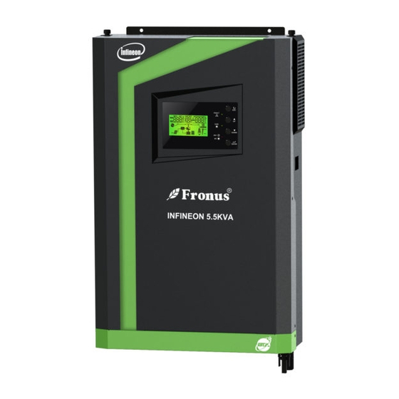
Product Overview 1. LCD display 2. Status indicator 3. Charging indicator 4. Fault indicator 5. Function buttons 6. Power on/off switch 7. AC input 8. AC output 9. PV input 10. Battery input 11. Circuit breaker 12. USB communication port 13. -
Page 6: Installation
INSTALLATION Unpacking and Inspection Before installation, please inspect the content. Be sure that nothing inside the package is damaged. You should have received the following items inside the package: Inverter x 1 User manual x 1 Communication cable x 1 ... -
Page 7: Battery Connection
Mounting the unit by screwing the two screws as shown below. It’s recommended to use M4 or M5 screws. Battery Connection CAUTION: For safety operation and regulation compliance, it’s requested to install a separate DC over-current protector or disconnection device between battery and the inverter. It may not be necessary to have a disconnection device in some applications, however, it’s still recommended to have over-current protection installed. - Page 8 3.5KVA 5.5KVA 5. Insert the battery wires flatly into battery connectors of inverter and make sure the bolts are tightened with torque of 2 Nm in clockwise direction. Make sure polarity at both the battery and the inverter/charge is correctly connected and conductors are tightly screwed into the battery terminals. Recommended tool: #2 Pozi Screwdriver 6.
-
Page 9: Ac Input/Output Connection
To reduce risk of injury, please use the proper recommended cable size as below. Suggested cable requirement for AC wires Cable (mm Model Gauge Torque Value Infineon 3.5KVA 12 AWG 1.2 Nm Infineon 5.5KVA 10 AWG 1.2 Nm Please follow these steps to implement AC input/output connection: 1. -
Page 10: Pv Connection
22 pcs 5500W 5.5KVA model) PV Module Wire Connection for Infineon 3.5KVA model Please take the following to implement PV module connection: 1. Remove insulation sleeve 10 mm for positive and negative conductors. 2. Suggest to put bootlace ferrules on the end of positive and negative wires with a proper crimping tool. - Page 11 4. Check correct polarity of wire connection from PV modules and PV input connectors. Then, connect positive pole (+) of connection wire to positive pole (+) of PV input connector. Connect negative pole (-) of connection wire to negative pole (-) of PV input connector. Screw two wires tightly in clockwise direction. Recommended tool: 4mm blade screwdriver PV Module Wire Connection for Infineon 5.5KVA model Step 1: Check the input voltage of PV array modules.
- Page 12 Insert striped cable into female terminal and crimp female terminal as shown below charts. Insert assembled cable into female connector housing as shown below charts. Insert striped cable into male terminal and crimp male terminal as shown below charts. Insert assembled cable into male connector housing as shown below charts. Then, use spanner to screw pressure dome tightly to female connector and male connector as shown below.
-
Page 13: Final Assembly
Final Assembly After connecting all wirings, please put bottom cover back by screwing two screws as shown below. Communication Connection Please use supplied communication cable to connect to inverter and PC. Insert bundled CD into a computer and follow on-screen instruction to install the monitoring software. For the detailed software operation, please check user manual of software inside of CD. -
Page 14: Operation
OPERATION Power ON/OFF Side view of unit Once the unit has been properly installed and the batteries are connected well, simply press On/Off switch (located on the side of the case) to turn on the unit. Operation and Display Panel The operation and the LCD module, shown in the chart below, is on the front panel of the inverter. -
Page 15: Lcd Display Icons
LCD Display Icons Icon Function description Input Source Information Indicates the AC input. Indicates the PV panel input Feed grid power, Indicate input voltage, input frequency, PV voltage, charger current, charger power, battery voltage. Configuration Program and Fault Information Indicates the setting programs. Indicates the warning and fault codes. - Page 16 Voltage mode Bottom three bars will be on and the top > 2.167 V/cell bar will flash. Floating mode. Batteries are fully charged. 4 bars will be on. In battery mode, it will present battery capacity. Load Percentage Battery Voltage LCD Display <...
-
Page 17: Lcd Setting
LCD Setting After pressing and holding ENTER button for 3 seconds, the unit will enter the Setup Mode. Press “UP” or “DOWN” button to select setting programs. Press “ENTER” button to confirm you selection or ESC button to exit. Setting Programs: Program Description Selectable option... - Page 18 Appliances (default) If selected, acceptable AC input voltage range will be within 90-280VAC. AC input voltage range If selected, acceptable AC input voltage range will be within 170-280VAC. AGM (default) Flooded Battery type User-Defined If “User-Defined” is selected, battery charge voltage and low DC cut-off voltage can be set up in program 26, 27 and 29.
- Page 19 Available options in 3.5KVA model: 22.0V 22.5V 23.0V (default) 23.5V 24.0V 24.5V 25.0V 25.5V Setting voltage point back Available options in 5.5.KVA model: to utility source when selecting “SBU priority” in program 01. 46V (default)
- Page 20 Available options in 3.5KVA model: Battery fully charged 24.5V 25.5V 26.5V 27V (default) 27.5V 28.5V Setting voltage point back to battery mode when selecting “SBU priority” in Available options in 5.5KVA model: program 01. Battery fully charged 54V (default)
- Page 21 If this inverter/charger is working in Line, Standby or Fault mode, charger source can be programmed as below: Solar first Solar energy will charge battery as first priority. Utility will charge battery only when solar energy is not available. Solar and Utility (default) Solar energy and utility will charge Charger source priority: battery at the same time.
- Page 22 3.5KVA default setting: 28.2V 5.5KVA default setting: 56.4V Bulk charging voltage (C.V voltage) If self-defined is selected in program 5, this program can be set up. Setting range is from 25.0V to 31.5V for 3.5KVA model and 48.0V to 61.0V for 5.5KVA model. Increment of each click is 0.1V. 3.5KVA default setting: 27.0V 6000VA default setting: 54.0V Floating charging voltage...
- Page 23 3.5KVA default setting: 29.2V 5.5KVA default setting: 58.4V Battery equalization voltage Setting range is from 25.0V to 31.5V for 3.5KVA model and 48.0V to 61.0V for 5.5KVA model. Increment of each click is 0.1V. 60min (default) Setting range is from 5min to 900min. Increment of each click is 5min.
-
Page 24: Display Setting
Display Setting The LCD display information will be switched in turns by pressing the “UP” or “DOWN” button. The selective information will be switched as per the following orders: input voltage, input frequency, PV voltage, charging current, charging power, battery voltage, output voltage, output frequency, load percentage, load in Watt, load in VA, load in Watt, DC discharging current, main CPU Version. - Page 25 PV current = 2.5A PV current PV power = 500W PV power AC and PV charging current=50A PV charging current=50A Charging current AC charging current=50A...
- Page 26 AC and PV charging power=500W PV charging power=500W Charging power AC charging power=500W Battery voltage=25.5V, output voltage=230V Battery voltage and output voltage Output frequency=50Hz Output frequency Load percent=70% Load percentage...
- Page 27 When connected load is lower than 1kVA, load in VA will present xxxVA like below chart. Load in VA When load is larger than 1kVA (≧1KVA), load in VA will present x.xkVA like below chart. When load is lower than 1kW, load in W will present xxxW like below chart.
-
Page 28: Operating Mode Description
Operating Mode Description Operation mode Description LCD display Charging by utility and PV energy. Charging by utility. Charging by PV energy. Standby mode No charging. Note: No output is supplied by the *Standby mode: The inverter unit but it still can charge is not turned on yet but at this batteries time, the inverter can charge... - Page 29 Operation mode Description LCD display Charging by utility and PV energy. Charging by utility. Fault mode Note: *Fault mode: Errors are PV energy and utility can caused by inside circuit error charge batteries. or external reasons such as over temperature, output short Charging by PV energy.
- Page 30 Operation mode Description LCD display If “solar first” is selected as output source priority and solar energy is not sufficient to provide the load, solar energy and the utility will provide the loads and charge the battery at the same time. If either “solar first”...
-
Page 31: Battery Equalization Description
Operation mode Description LCD display Power from battery and PV energy. PV energy will supply power to the loads and charge battery at the same time. No utility is available. The unit will provide output Battery Mode power from battery and/or PV power. - Page 32 Equalize Charging and Timeout In Equalize Mode, the controller will supply power to charge battery as much as possible until battery voltage reach the equalization voltage. Then, constant-voltage regulation is applied to maintain battery voltage at the equalization level. The battery will remain in the Equalize Mode until the equalization timer runs out. However, in Equalize Mode, if the battery equalization timer runs out and the battery voltage doesn’t recover to the battery equalization voltage point, the charge controller will extend the battery equalized time until battery voltage achieves equalization voltage.
-
Page 33: Fault Reference Code
Fault Reference Code Fault Code Fault Event Icon on Fan is locked when inverter is off. Over temperature Battery voltage is too high Battery voltage is too low Output short circuited or over temperature is detected by internal converter components. Output voltage is too high. -
Page 34: Warning Indicator
Warning Indicator Warning Warning Event Audible Alarm Icon flashing Code Beep three times every Fan is locked when inverter is on. second Over temperature None Battery is over-charged Beep once every second Low battery Beep once every second Overload Beep once every 0.5 second Output power derating Beep twice every 3 seconds PV energy is low. -
Page 35: Clearance And Maintenance For Anti-Dust Kit
CLEARANCE AND MAINTENANCE FOR ANTI-DUST KIT Overview Every inverter is already installed with anti-dusk kit from factory. Inverter will automatically detect this kit and activate internal thermal sensor to adjust internal temperature. This kit also keeps dusk from your inverter and increases product reliability in harsh environment. -
Page 36: Specifications
SPECIFICATIONS Table 1 Line Mode Specifications INVERTER MODEL Infineon 3.5KVA Infineon 5.5KVA Input Voltage Waveform Sinusoidal (utility or generator) Nominal Input Voltage 230Vac 170Vac± 7V (UPS); Low Loss Voltage 90Vac± 7V (Appliances) 180Vac± 7V (UPS); Low Loss Return Voltage 100Vac± 7V (Appliances) High Loss Voltage 280Vac±... - Page 37 Table 2 Inverter Mode Specifications INVERTER MODEL Infineon 3.5KVA Infineon 5.5KVA 4000VA 6000VA Rated Output Power Pure Sine Wave Output Voltage Waveform 230Vac± 5% Output Voltage Regulation 50Hz Output Frequency Peak Efficiency Overload Protection 5s@≥130% load; 10s@105%~130% load 2* rated power for 5 seconds...
- Page 38 Table 3 Charge Mode Specifications Utility Charging Mode INVERTER MODEL Infineon 3.5KVA Infineon 5.5KVA Charging Algorithm 3-Step AC Charging Current (Max) 60Amp (@V =230Vac) Flooded Battery 29.2 58.4 Bulk Charging Voltage AGM / Gel Battery 28.2 56.4 Floating Charging Voltage...
-
Page 39: Trouble Shooting
TROUBLE SHOOTING Problem LCD/LED/Buzzer Explanation / Possible cause What to do Unit shuts down LCD/LEDs and buzzer automatically will be active for 3 The battery voltage is too low 1. Re-charge battery. during startup seconds and then (<1.91V/Cell) 2. Replace battery. process. -
Page 40: Appendix: Approximate Back-Up Time Table
Appendix: Approximate Back-up Time Table Model Load (VA) Backup Time @ 24Vdc 100Ah (min) Backup Time @ 24Vdc 200Ah (min) 1100 1200 1500 Infineon 3.5KVA 1800 2100 2400 2700 3000 Model Load (VA) Backup Time @ 48Vdc 100Ah (min) Backup Time @ 48Vdc 200Ah (min) 1288 1000 1500...
Need help?
Do you have a question about the Infineon 3.5KVA and is the answer not in the manual?
Questions and answers