Hach ORBISPHERE C1100 User Manual
Ozone sensor
Hide thumbs
Also See for ORBISPHERE C1100:
- User manual (92 pages) ,
- User manual (38 pages) ,
- Basic user manual (130 pages)

Related Manuals for Hach ORBISPHERE C1100


Summary of Contents for Hach ORBISPHERE C1100
- Page 1 DOC024.52.93019 ORBISPHERE Model C1100 Ozone Sensor User Manual 07/2020, Edition 5...
-
Page 3: Table Of Contents
Table of Contents Section 1 General Information ......................3 1.1 Safety information ........................3 1.1.1 Use of hazard information ....................3 1.1.2 Service and repairs ......................3 1.1.3 Precautionary labels......................3 1.2 Product disposal .......................... 4 Section 2 Technical Specifications .................... - Page 4 Table of Contents...
-
Page 5: Section 1 General Information
1.1.2 Service and repairs None of the sensor’s components can be repaired by the user. Only personnel from Hach Lange or its approved representative(s) is (are) authorized to attempt repairs to the sensor and only components formally approved by the manufacturer should be used. -
Page 6: Product Disposal
European public disposal systems after 12 August 2005. Hach Lange will offer to take back (free of charge to the customer) any old, unserviceable or redundant analyzers and systems which carry the above symbol, and which were originally supplied by Hach Lange. -
Page 7: Section 2 Technical Specifications
Section 2 Technical Specifications Specifications are subject to change without notice. 2.1 Sensor weight and dimensions The sensor weight is approximately 300 grams. Figure 1 Sensor Dimensions 2.2 Sensor configuration The standard sensor configurations for Beverage, Pharmaceutical and Life Science applications are: Sensor Membrane Cartridge... -
Page 8: Sensor Membrane Specifications
Technical Specifications 2.3 Sensor membrane specifications 2.3.1 Ozone sensors Table 1 Membrane specifications - Ozone sensors 2956A 29552A Recommended applications Trace measurement High concentration (> 1 mg/l) Material PTFE Thickness [µm] Calibration gas Span gas or air Dissolved measurement range 0 ppb to 50 ppm 0 ppb to 200 ppm The greater of ±1% of reading... -
Page 9: Section 3 Introduction
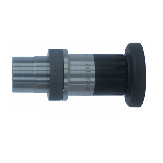
Section 3 Introduction 3.1 What you have received 3.1.1 C1100 electrochemical sensor The sensor may be delivered separately or as part of an ORBISPHERE system, depending on the individual order. Figure 2 C1100-S00 sensor with storage cap The sensor (as illustrated in Figure 2 above) will be delivered fitted with a plastic screw-on storage cap to protect the sensor head. -
Page 10: Sensor Recharge Kit
Introduction 3.1.3 Sensor recharge kit A recharge kit (as illustrated in Figure 4 below) should have been ordered with the sensor as this will be required to initially make the sensor operational. It is also required for sensor cleaning and membrane replacement procedures. Note: The recharge kit for ozone has a green sticker on the front of the box. -
Page 11: Sensor Components
Introduction 3.2 Sensor components The following illustration shows the assembled sensor with the storage cap and sensor collar removed and the exploded view of the main sensor components. To remove the storage cap, you will first have to unscrew and remove the sensor base. Figure 6 Sensor components 1 - Protection cap locking washer 4 - Cartridge containing electrolyte and membrane... - Page 12 Introduction...
-
Page 13: Section 4 Installation
The following instructions detail the steps required to make the sensor operational. Should you have any questions, your Hach Lange representative will be pleased to help. Note: It is advisable to perform this procedure with the plastic sensor base installed so as to avoid any damage to the connection socket and also to provide a suitable stand for the sensor when required. - Page 14 Installation 2. Pull/twist off the protection cap and put to ® one side. Remove the Dacron mesh from inside the cap and discard it. 3. Hold the sensor with the membrane facing down to avoid spilling any electrolyte, then carefully unscrew the shipment cartridge. Drain the old electrolyte into a sink and flush away.
- Page 15 Installation 7. Place the recharge cartridge container on a flat work surface and, keeping the container upright to avoid spilling any of the electrolyte inside, carefully unscrew the top. 8. Remove the packing component from the center of the cartridge, making sure that the O-ring on top of the cartridge remains in place.
- Page 16 Installation 13. Continue turning until the cartridge is attached to the sensor, and the sensor is automatically released from the container. 14. The empty container, the screw top and packing component can be discarded. Note: It is normal that some of the electrolyte will overflow from the replacement cartridge and into the plastic container.
- Page 17 Installation 21. Push the protection cap firmly into place, making sure one of the four slots in the protection cap fits over the small locking pin (highlighted right). If it is necessary to turn the protection cap to fit over the locking pin, ensure you only turn it clockwise to avoid unscrewing the cartridge.
-
Page 18: Sensor Installation
Note: There may be situations where not all the above conditions can be met. If this is the case, or you have any concerns, please consult your Hach Lange representative to appraise the situation and define the best applicable solution. -
Page 19: Sensor Removal
Installation 4.2.3 Sensor removal • If not using the ORBISPHERE 32003 insertion/extraction valve (see details on page 18) you will need to shut off the sample flow and drain the sampling circuit of liquid. • Remove the sensor cable connected at the sensor end. •... -
Page 20: The 32003 Insertion/Extraction Valve
Installation 4.3.2 The 32003 insertion/extraction valve The ORBISPHERE 32003 insertion/extraction valve (illustrated below) allows for sensor removal and installation without having to drain the fluid in the line. It can withstand a pressure of up to 20 bars, with the sensor in place or not. Sensor insertion is made by inserting the sensor into the housing and tightening the retaining collar until it stops. -
Page 21: Orbisphere Flow Chambers
Installation 4.3.5 ORBISPHERE flow chambers The ORBISPHERE 32001.xxx flow chambers are used to draw liquid samples past the sensor. They are available in several materials, depending on the application. They connect to 6-mm or ¼" stainless steel tubing by means of two Swagelok™ fittings. If necessary, copper or plastic tubing with low permeability can be substituted. - Page 22 Installation...
-
Page 23: Section 5 Maintenance And Troubleshooting
Section 5 Maintenance and Troubleshooting 5.1 Maintenance C A U T I O N Multiple hazards. Only qualified personnel must conduct the tasks described in this section of the document. 5.1.1 Electrochemical cleaning and regeneration center The ORBISPHERE 32301 is a very efficient cleaning and regeneration tool for electrochemical sensors. - Page 24 Maintenance and Troubleshooting A sensor recharge kit is required as it contains all the components necessary for this membrane replacement and sensor head cleaning process. Refer to 3.1.3 Sensor recharge kit on page Note: It is advisable to perform this procedure with the plastic sensor base installed so as to avoid any damage to the connection socket and also to provide a suitable stand for the sensor when required.
- Page 25 Maintenance and Troubleshooting 6. Remove the tool and tap it face down on a flat work surface to remove any powdery deposit. Check the sensor to ensure that all deposits have been removed from the anode. If not, repeat step 5. until the anode regains its bright silver appearance. 7.
- Page 26 Maintenance and Troubleshooting 10. Polish the electrodes by moving the sensor face in a circular direction against the liquid in the polishing cloth for about 30 seconds. 11. Remove the polishing tool from the sensor. Remove any polish deposits by rinsing the sensor head under a tap for 30 seconds, aiming the jet of water directly onto the sensor head.
- Page 27 Maintenance and Troubleshooting 16. On the sensor cleaning and regeneration center, turn the knob to the Guard position and press the TIMER switch. Again, watch for the formation of bubbles and repeat the cleaning process if necessary. 17. On the sensor cleaning and regeneration center, turn the knob to the Cathode position and press the TIMER switch.
- Page 28 Maintenance and Troubleshooting 21. Place the recharge cartridge container on a flat work surface and, keeping the container upright to avoid spilling any of the electrolyte inside, carefully unscrew the top. Remove the packing component from the center of the cartridge, and make sure that the O-ring remains in place on top of the cartridge.
- Page 29 Maintenance and Troubleshooting 26. If not using a protection cap with grille proceed to step 27. Otherwise, take a new Dacron® mesh patch from the box of O-rings in the recharge kit. Place the mesh in the center of the protection cap.
-
Page 30: Troubleshooting
Maintenance and Troubleshooting 5.2 Troubleshooting 5.2.1 Ozone sensor When the O sensor has been properly calibrated using the Orbisphere measuring instrument, the sensor has to settle down for up to 24 hours when used in very low O concentration conditions. Table 2 Troubleshooting - Ozone sensor Problem Probable Cause... -
Page 31: Section 6 Accessories And Spare Parts
Section 6 Accessories and Spare Parts WA R N I N G Personal injury hazard. Use of non-approved parts may cause personal injury, damage to the instrument or equipment malfunction. The replacement parts in this section are approved by the manufacturer. Note: Product and Article numbers may vary for some selling regions. -
Page 32: Certificates
Accessories and Spare Parts Table 5 Flow chambers and installation devices Part N° Description 32003 Sensor insertion device; for use with Tuchenhagen adapter 33095 28 mm stationary housing for installation on Varinline® access units 6.4 Certificates Table 6 Certificates Part N° Description 33181 C1100 Material certificate EN 10204 2.2... - Page 33 Tel. +49 (0) 2 11 52 88-320 SWITZERLAND Fax (970) 669-2932 Fax +49 (0) 2 11 52 88-210 Tel. +41 22 594 6400 orders@hach.com info-de@hach.com Fax +41 22 594 6499 www.hach.com www.de.hach.com © Hach Company/Hach Lange GmbH, 2012–2015, 2020. All rights reserved.
Need help?
Do you have a question about the ORBISPHERE C1100 and is the answer not in the manual?
Questions and answers