Table of Contents
Advertisement
Advertisement
Table of Contents

Summary of Contents for Viper 500.4
- Page 1 200.4 models 500.4...
- Page 2 © 2002 Directed Electronics, Inc...
-
Page 3: Table Of Contents
Featuring high-efficiency MOSFET power supplies, flexible on-board crossovers, and state of the art audio design, Viper Audio power amplifiers will excite and TABLE OF CONTENTS Limited Two-Year Consumer Warranty ......4 Features . -
Page 4: Limited Two-Year Consumer Warranty
LIMITED TWO-YEAR CONSUMER WARRANTY Directed Electronics, Inc. promises to the original purchaser, to replace this product should it prove to be defective in workman- ship or material under normal use, for a period of two years from the date of purchase by the dealer as indicated by the date code marking of the product PROVIDED the product was installed by an... -
Page 5: Features
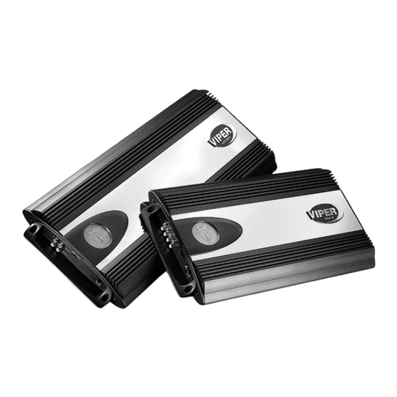
Thermal, DC offset, reverse polarity and short circuit protection. Top-mounted controls located under illuminated Viper snake logo trim piece. The Viper logo and Viper badge are four-way adjustable for a custom look. WARNING High-powered car audio systems may produce... -
Page 6: Installation Guidelines
INSTALLATION GUIDELINES 1. Please read this owner’s manual carefully before installing this ampli- fier. 2. Disconnect the battery ground terminal prior to making any elec- trical connections. 3. Check for any hazards or obstruc- tions such as gas tanks, fuel or brake lines, and wiring harnesses before mounting the amplifier. -
Page 7: Wire Connector Plugs
WIRE CONNECTOR PLUGS Power and speaker wire connections on Viper Audio power amplifiers are performed with the use of specially designed connectors that allow for ease of wire termination and installation convenience. -
Page 8: Front Panel Connections/Status Led
On four, five, and six channel ampli- fiers it is the summed stereo output FIGURE 1—AMPLIFIER CONNECTIONS 200.4/500.4 FRONT REAR PANEL CONNECTIONS 1. S S p p e e a a k k e e r r O O u u t t T T e e r r m m i i n n a a l l s s - Connect the speakers to these terminals. - Page 9 5. G G r r o o u u n n d d - Connect this terminal directly to the sheet metal chassis of the vehicle, using the shortest wire necessary to make this FIGURE 2—AMPLIFIER CONNECTIONS 500.4 REAR FIGURE 3—AMPLIFIER CONNECTIONS 200.4 REAR © 2002 Directed Electronics, Inc connection. Always use wire of the same gauge or larger than the (+) 12 volt power wire.
-
Page 10: Top Panel Controls
TOP PANEL CONTROLS 1. I I n n p p u u t t G G a a i i n n A A d d j j u u s s t t m m e e n n t t - Controls amplifier sensitivity and is used to match the input level of the ampli- fier to the output level of the signal... -
Page 11: Top Panel Features
Viper Badge Mounting The Viper Badge can be rotated in 90- degree increments to accommodate the amplifier’s final mounting position. 1. Determine the final mounting posi- tion of the amplifier. -
Page 12: Speaker Wiring Diagrams
SPEAKER WIRING DIAGRAMS (bottom view four channel shown) Stereo Operation (bottom view two channel shown) Bridged operation N N O O T T E E : : For bridged two-channel operation as shown below, connect the right channel RCA cables to the Front inputs of the amplifier, and left channel RCA cables to the rear inputs of the amplifier. - Page 13 (bottom view) Simultaneous stereo/mono operation © 2002 Directed Electronics, Inc...
-
Page 14: Crossover Settings And Gain Adjustment
CROSSOVER SETTINGS AND GAIN ADJUSTMENT Your Viper Audio power amplifier needs to be adjusted carefully to achieve maximum performance. These are some guidelines to follow when fine-tuning the amplifier. For full-range and simultaneous stereo/mono bass applications, the crossover selection switch should be set to FLAT. If the amplifier is driving your subwoofers, set the switch to LPF, and for mid-bass/midrange output, set to HPF. -
Page 15: Specifications
Bass Equalization Input Impedance Input Sensitivity Output Impedance Supply Voltage Fusing and Power Minimum Cable Requirements (AWG) (Per amp, trunk mounted) © 2002 Directed Electronics, Inc Viper model 200.4 500.4 watts watts watts watts watts watts watts watts Greater than 95 dB 20-20,000 Hz ±... - Page 16 Directed Electronics, Inc. Vista, California 92083 www.directed.com Quality Directed products are sold and serviced throughout North America and around the world Call 800 274 0200 for more information about our products and services © 2002 Directed Electronics, Inc. - All rights reserved - G46042/44 02/02 The company behind this system is Directed Electronics, Inc.

Need help?
Do you have a question about the 500.4 and is the answer not in the manual?
Questions and answers