Table of Contents
Advertisement
Original
OPERATING MANUAL
P030 Chiller
Glen Dimplex Deutschland GmbH
Geschäftsbereich RIEDEL Kältetechnik
Am Goldenen Feld 18
D-95326 Kulmbach
Phone: +49 (0) 9221 / 709 555
Fax:
+49 (0) 9221 / 709 549
HEADQUARTERS GERMANY
NORTH AMERICA
PARTS & SERVICE
Phone: +49 (0) 9221 / 709 545
Phone: ++1-877 RIEDEL1
Fax:
+49 (0) 9221 / 709 529
Phone: ++1-877 -743 -3351
Fax: ++1-734 -595 -9829
HOTLINE
e-mail: service@Riedel-Cooling.com
http://www.Riedel-Cooling.com
e-mail: service@riedel-usa.com
http://www.riedel-usa.com
454522.68.07-01-E
12.02.0032
Advertisement
Table of Contents

Summary of Contents for Riedel P030
- Page 1 Original OPERATING MANUAL P030 Chiller Glen Dimplex Deutschland GmbH Geschäftsbereich RIEDEL Kältetechnik Am Goldenen Feld 18 D-95326 Kulmbach Phone: +49 (0) 9221 / 709 555 Fax: +49 (0) 9221 / 709 549 HEADQUARTERS GERMANY NORTH AMERICA PARTS & SERVICE Phone: +49 (0) 9221 / 709 545...
- Page 2 ENGLISH Translation of the Original This document was drawn up by the Technical Documentation Dept. of Glen Dimplex Deutschland GmbH. Glen Dimplex reserves all rights to this documentation, especially the right to reproduce, distribute and translate this document. This also applies with respect to application for patents and industrial rights. No part of this document may be reproduced, processed, copied or distributed by either conventional or electronic means without the prior written consent of Glen Dimplex.
-
Page 3: Table Of Contents
OTICES ..........................8 ANDLING OF EFRIGERANTS ............................9 AFETY EQUIREMENTS P030 C ........................10 URPOSE OF THE HILLER ........................11 ECLARATION OF ONFORMITY DESCRIPTION OF THE P030 CHILLER................12 P030 C ..........................12 VERVIEW HILLER ..........................12 EFRIGERATION IRCUIT ..............................14 ATER IRCUIT .............................14 OOLING UPPLY ............................15... - Page 4 ENGLISH Translation of the Original 12.1 .......................... 37 EPLACING ILTER LEMENT PERIODICAL INSPECTIONS AND TESTS..............38 MALFUNCTIONS / TROUBLESHOOTING ..............40 14.1 ST 181 ..........40 ALFUNCTIONS ROUBLESHOOTING OF ONTROL AND PERATING OPTIONS .......................... 44 15.1 .............................. 44 ATER IRCUIT 15.2 ............................
-
Page 5: For Your Safety
ENGLISH FOR YOUR SAFETY 1 FOR YOUR SAFETY 1.1 Regulations Design, construction and development of the P030 Chiller are in compliance with the following national and international regulations. EC Directives / Standards EC Machinery Directive 2006/42/EC EC EMC Directive 2004/108/EC... -
Page 6: Signs And Symbols
FOR YOUR SAFETY ENGLISH Translation of the Original 1.2 Signs and Symbols Throughout this operating manual, the information and notices below are identified by the following graphical symbols: Danger! Safety note pointing out an imminent danger. Failure to heed the warning may result in serious bodily injury and even death. -
Page 7: Safety Notices
• Anyone working on the refrigeration circuit must be protected by personal protective equipment. • The P030 Chiller is to be used exclusively for the cooling of water and water- glycol mixtures in accordance with predefined specifications. Notice! • Watch out for any incompatibilities of materials in the entire water circuit. -
Page 8: Handling Of Refrigerants
• When handling refrigerants, all legal provisions and guidelines must be complied with. Only qualified personnel may perform these activities. The operator of the P030 Chiller is responsible for the proper disposal of used refrigerants and system parts. 454522.68.07-01-E 27.06.2012... -
Page 9: Safety Requirements
The owner or operator has the obligation to keep a logbook for the P030 Chiller. he system logbook must either be available on site near the P030 Chiller, or in the event that the data are stored in a computer of the owner or operator, a printout of the log must be kept in the vicinity of the P030 Chiller. -
Page 10: Purpose Of The P030 Chiller
1.6 Purpose of the P030 Chiller The P030 Chiller described in this manual is designed for outdoor use and is intended exclusively for the cooling of water, or a water-glycol mixture (ratio 60: 40%), for the system separator (COO of the P030 Chiller). -
Page 11: Declaration Of Conformity
Translation of the Original ENGLISH FOR YOUR SAFETY 1.7 Declaration of Conformity 454522.68.07-01-E 27.06.2012... -
Page 12: Description Of The P030 Chiller
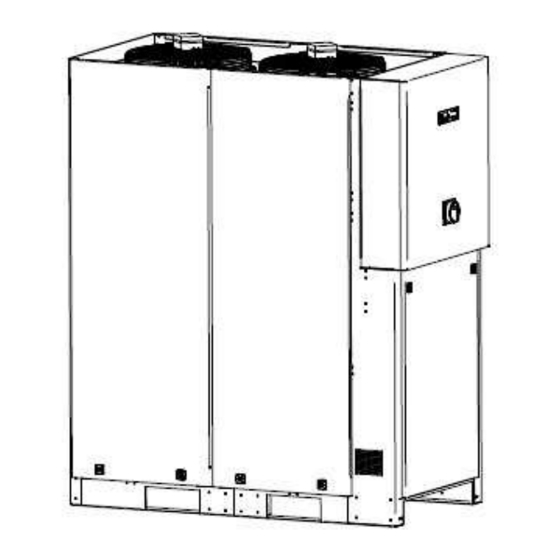
Translation of the Original 2 DESCRIPTION OF THE P030 CHILLER The P030 Chiller is a unit ready for plug-in and is equipped with a refrigeration and water circuit including all fittings and regulating/control devices required for automatic operation. The heat extracted from the water is given off to the ambient air by means of the refrigeration circuit via the condenser and the fans. - Page 13 Translation of the Original ENGLISH DESCRIPTION OF THE P030 CHILLER The vaporised refrigerant is drawn in by the three compressors (1) and is then compressed (rise in pressure and temperature). The refrigerant also absorbs the heat of the compressor motor, and this heat is given off to the surrounding air by the condenser (2) –...
-
Page 14: Water Circuit
The water circuit of the P030 Chiller together with the connecting hoses constitutes the transport system of the cooling water between the P030 Chiller and the primary circuit of the system separator (COO). This closed water circuit is designed in accordance with requirements and is equipped with all fittings and components required for safety and monitoring purposes. -
Page 15: Safety Devices
The high-pressure control is designed to protect the P030 Chiller against extremely high operating pressure in the refrigeration circuit. In the event of a malfunction, the HP control switches the P030 Chiller off and the malfunction is indicated on the control panel of the control and operating unit. -
Page 16: Electrical/Control Equipment
The connection of the P030 Chiller to the equipment to be cooled is effected via a potential-free interface. To achieve a galvanic isolation of the equipment to be cooled and the P030 Chiller, the connection is accomplished by means of optical-fibre cables. -
Page 17: Technical Data
Translation of the Original ENGLISH TECHNICAL DATA 3 TECHNICAL DATA 3.1 Hydraulic Data Description Unit Values Designation: P030 Chiller Type 2NK6 772 C Cooling capacity Cooling medium, primary water/glycol mixture circuit 60 %/40 % Cooling medium outlet ° C 9 ± 3 K... -
Page 18: Name Plate
TECHNICAL DATA ENGLISH Translation of the Original 3.4 Name Plate Name Plate 3.4.1 Installation Location of the Type Plate The name plate is attached to the front of the control cabinet, at the bottom on the right. Name plate Barcode identification label Location of the name plate and the barcode identification label... -
Page 19: Transport And Storage
• Damaged units must be sorted out immediately! The in-house transport is carried out by a forklift, lift truck or crane. The P030 Chiller must be deposited on a level surface to prevent any distortion of the base-frame. 4.1 Transport Specification −... -
Page 20: Transport Using A Forklift
4.2 Transport Using a Forklift To move the P030 Chiller with a fork lift, the recesses provided at the broadside of the base-frame of the unit should exclusively be used. Do not lift the unit until the forks have been inserted horizontally all the way beneath the unit, symmetrically to the centre of gravity of the P030 Chiller. -
Page 21: Transport Using A Lift Truck
Handling the unit from the narrow side: The P030 Chiller can be moved with a lift truck with the forks being inserted under the load from the narrow side. To ensure that the forks can be inserted under both cross beams, a minimum fork length must be maintained. -
Page 22: Transport Using A Crane
ENGLISH Translation of the Original 4.4 Transport Using a Crane For the transport of the P030 Chiller, lifting eyes are provided in the upper frame enabling a 4-leg sling load arrangement. Load suspension devices Wire rope slings (lifting rope assemblies) according to DIN 3088, or sling chains (lifting chain assemblies) according to DIN 5687/ 5688. -
Page 23: Storage Of The P030 Chiller
TRANSPORT AND STORAGE 4.5 Storage of the P030 Chiller The P030 Chiller must be stored on a level surface, or supported on additional square beams, in a dry room, protected from frost. Permissible storage temperature range: −20° C to 60° C. -
Page 24: Installation
Transport packaging to be removed before turning the unit on! Installation of the P030 Chiller The P030 Chiller is to be installed outdoors on a level, horizontal surface with adequate load bearing capability. Any attachments to the floor, intermediate spacers or anti-vibration mountings are not required. Any national or local installation and mounting regulations must be complied with! For different installation conditions, consult the manufacturer. -
Page 25: Mounting
• Where the piping system is installed at the installation site by the customer, care must be taken that the pipe system is free from contamination (lines may have to be flushed prior to connecting the P030 Chiller). 454522.68.07-01-E 27.06.2012... -
Page 26: Electro-Technical Connection
Establish electro-technical connection in accordance with the circuit diagram (see Appendix) − The P030 Chiller is ready for connection to a remote control unit. In the delivery state a jumper wire is inserted across the terminals. The general fault indicator is wired to the terminal in the form of a potential-free contact. - Page 27 Translation of the Original ENGLISH MOUNTING Installation instructions for optical fibre cable 454522.68.07-01-E 27.06.2012...
-
Page 28: Commissioning
Flushing, Filling and Venting Notice! • Due to the fact that the P030 Chiller and its downstream equipment to be cooled can be installed at different levels, it must be ensured that the system is properly filled and vented. 454522.68.07-01-E... - Page 29 Translation of the Original ENGLISH COMMISSIONING Step Action Connect the Filler device to the K-F-E valve [3] at the pump. Use a transparent hose for connecting it to the K-F-E valve [4]. Put the open end of that hose into a pan or canister. ATTENTION: Do not drain Glycol or Glycol mixtures into the sewage drain! Open only the K-F-E valve [3] at the pump, all others have to be closed.
-
Page 30: Initial Start-Up Of The Pump
-1- position (see circuit diagram in the Appendix). Clear all pending fault messages at the control and operating unit. The P030 Chiller is ready for operation and the control and operating unit takes over the control of the water outlet temperature. -
Page 31: Decommissioning
• The safety notices contained in Chapter 1 must be complied with! If the P030 Chiller is not used for an extended period or if it is to be disassembled, the unit has to be taken out of service. The following procedure should be followed: −... -
Page 32: Shutdown In Emergencies
• The safety notices contained in Chapter 1 must be complied with! − Turn power disconnect switch (main switch) on the control cabinet of the P030 Chiller to the "OFF" position − „0“ −. Main switch in "0" position 454522.68.07-01-E... -
Page 33: Environmental Requirements
DIN EN 378 are to be complied with. Notice! • The operator of the P030 Chiller is responsible for the proper disposal of used fuels, oils and system components. The disposal of the water containing additives is to be effected in agreement with the competent local authorities. -
Page 34: Operation Of Control And Operating Unit
Translation of the Original 11 OPERATION OF CONTROL AND OPERATING UNIT The P030 Chiller is switched on by means of power disconnect switch (main switch) which also doubles as an EMERGENCY STOP switch. The P030 Chiller is now ready for operation, and control and operating unit takes over the control of the water outlet temperature. - Page 35 Translation of the Original ENGLISH OPERATION OF CONTROL AND OPERATING UNIT In the normal state, the flow temperature of the water circuit is indicated on the display. Setpoint adjustment The setpoint is adjusted by simultaneously pressing the SET button and the UP or DOWN button. 454522.68.07-01-E 27.06.2012...
-
Page 36: Maintenance
The safety notices contained in Chapter 1 must be complied with! • Always disconnect the the P030 Chiller from the power supply before attempting to open the cabinet! No specific refrigeration technology knowledge is required for the performance of maintenance activities. -
Page 37: Replacing Filter Element
Translation of the Original ENGLISH MAINTENANCE 12.1 Replacing Filter Element The filter element can be replaced without any tools. Proceed as follows: − Pull at the lower edge of the protective grille until it can be removed from the magnetic fixing points. -
Page 38: Periodical Inspections And Tests
Always disconnect the P030 Chiller from the power supply before attempting to open the cabinet! During the lifetime of the P030 Chiller, inspections and tests (not included in the scope of the warranty) must be carried out in accordance with national regulations! If there are no local regulations relating to periodical inspections, regular device-specific tests have to be performed based on EN 378-2. - Page 39 Inspection of the mounting and attachment of all piping and components for security − Visual inspection of the water circuits under operating conditions for leaks − Check that the operating manual is available at the P030 Chiller Notice! • All periodical inspections and tests must be documented in the system logbook.
-
Page 40: Malfunctions / Troubleshooting
MALFUNCTIONS / TROUBLESHOOTING ENGLISH Translation of the Original 14 MALFUNCTIONS / TROUBLESHOOTING Caution! • The safety notices contained in Chapter 1 must be complied with! The basis for troubleshooting are the circuit diagram, the flow diagram and the messages displayed on the control panel. - Page 41 Reduce load consumption or shut off After a malfunction due to excessively high pressure, the pressostat must be reset manually so that the P030 Chiller can be restarted. The compressors and fans will be enabled after a delay of 180 seconds.
- Page 42 MALFUNCTIONS / TROUBLESHOOTING ENGLISH Translation of the Original Fault Display Malfunction / Cause Remedy Fault due to low pressure - Ambient temperature too low Increase ambient temperature - Water temperature too low Increase water temperature - Water volume too low Clean filter, replace if necessary Filter dirty Check shut-off valve...
- Page 43 Translation of the Original ENGLISH MALFUNCTIONS / TROUBLESHOOTING Fault Display Malfunction / Cause Remedy Fault message Digital Fault input E7 Check filling pressure Flow control switch has tripped - Leaks in water circuit Check water circuit for leaks, top up water up to the MAX.
-
Page 44: Options
If the minimum flow rate is fallen short of, the pump is switched off. 15.2 Electrical System Glass fibre cable A 100m long glass fibre cable is available as an option. As standard the P030 Chiller communicates with the COO via a glass fibre cable up to 50m in length. Control cabinet heater...
Need help?
Do you have a question about the P030 and is the answer not in the manual?
Questions and answers