Table of Contents
Advertisement
Quick Links
Box-SM 2 650x650
Box-SL 2 650x650
BOX-SM 2 (for MONOsplit systems):
Series IB2-XY from 27M to 53M
BOX-SL 2 (for LIGHT Commercial systems):
Series S.IB2+MC2-Y from 35M to 53M
Nominal cooling capacity
from 2,6 kW to 5,3 kW
R-32
INSTALLATION AND OPERATING MANUAL
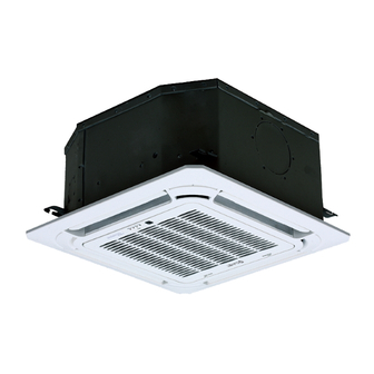
COMPACT FOUR-WAY CASSETTE
Change living home
Advertisement
Chapters
Table of Contents
Troubleshooting

Related Manuals for CLIVET Box-SM 2 650x650


Summary of Contents for CLIVET Box-SM 2 650x650
- Page 1 INSTALLATION AND OPERATING MANUAL Box-SM 2 650x650 Box-SL 2 650x650 COMPACT FOUR-WAY CASSETTE BOX-SM 2 (for MONOsplit systems): Series IB2-XY from 27M to 53M BOX-SL 2 (for LIGHT Commercial systems): Series S.IB2+MC2-Y from 35M to 53M Nominal cooling capacity from 2,6 kW to 5,3 kW...
- Page 2 Table of Contents Installation Manual IMPORTANT NOTE: Read this manual carefully before installing or operating your new air conditioning unit. Make sure to save this manual for future reference. Accessories ............ Safety Precautions ........Installation Overview ....... Indoor Unit Installation ......
-
Page 3: Table Of Contents
Refrigerant Piping Connection ....... A. Notes on Pipe Length and Elevation ....B. Refrigerant Piping Connection Instructions ... 17 C. Installation Of The Throttle ....... Wiring ..........a. Power Specifications ....b. Outdoor Unit Wiring ....c. Indoor Unit Wiring ....... - Page 4 Accessories The air conditioning system comes with the following accessories. Use all of the installation parts and accessories to install the air conditioner. Improper installation may result in water leakage, electrical shock and fire, or cause the equipment to fail. Name Shape Quantity...
- Page 5 Safety Precautions Read Safety Precautions Before Installation Incorrect installation due to ignoring instructions can cause serious damage or injury. The seriousness of potential damage or injuries is classified as either a WARNING or CAUTION. Failure to observe a warning may result in death. The appliance must be installed in accordance with national regulations.
- Page 6 Installation Overview INSTALLATION ORDER Install the indoor unit Install the outdoor unit Install the drainpipe (Page 7) (Page 11) (Page 13) Evacuate the refrigeration system Connect the wires Connect the refrigerant pipes (Page 22) (Page 20) (Page 15) Install the front panel Perform a test run (Page 24) (Page 26)
-
Page 7: Indoor Unit Installation
Indoor Unit Installation Indoor Unit Parts Drain pump (within indoor unit) Drain pipe Air outlet Louver Air inlet Display panel Front grille Refrigerant pipe Fig. 4.1 Safety Precautions CAUTION WARNING • Securely install the indoor unit on a • Install the indoor and outdoor units, cables structure that can sustain its weight. -
Page 8: Indoor Unit Installation Instructions
Indoor Unit Installation Instructions CAUTION NOTE: Panel installation should be done after DO NOT install the unit in the following piping and wiring. locations: In areas with oil drilling or fracking Step 1: Select installation location In coastal areas with high salt content in The indoor unit should be installed in a location the air that meets the following requirements:... - Page 9 Step 2: Hang indoor unit. 1. Use the included paper template to cut a rectangular hole in the ceiling, leaving at least 1m (39”) on all sides. The hole will be 60x60cm (23.6x23.6”) big. Be sure to mark the areas where ceiling hook holes will be drilled.
- Page 10 5. Mount the indoor unit. You will need two NOTE: Ensure that the indoor unit is level. The people to lift and secure it. Insert suspension unit is equipped with a built-in drain pump and bolts into the unit’ s hanging holes. Fasten float switch.
- Page 11 Outdoor Unit Installation (LIGHT Commercial system) The area must be free of combustible gases √ Outdoor Unit Installation Instructions and chemicals. √ The pipe length between the outdoor and Step 1: Select installation location. indoor unit may not exceed the maximum The outdoor unit should be installed in the allowable pipe length.
- Page 12 Split Type Outdoor Unit Drain Joint Installation (Refer to Fig 5.4, 5.5 and Table 5.1) Before bolting the outdoor unit in place, you must install the drain joint at the bottom of the unit. (See Fig. 5.7) 1. Fit the rubber seal on the end of the drain joint that will connect to the outdoor unit.
-
Page 13: Drainpipe Installation
Drainpipe Installation The drainpipe is used to drain water from the NOTE ON DRAINPIPE INSTALLATION unit. Improper installation may cause unit and When using an extended drainpipe, tighten • property damage. the indoor connection with an additional protection tube to prevent it from pulling CAUTION loose. - Page 14 3. Using a 65-mm (2.5”) core drill, drill a hole in the wall. Make sure that the hole is drilled at a slight downward angle, so that the outdoor end of the hole is lower than the indoor end by about 12mm (0.5”). This will ensure proper water drainage (See Fig.
-
Page 15: Refrigerant Piping Connection
Refrigerant Piping Connection Safety Precautions Notes On Pipe Length and Elevation Ensure that the length of the refrigerant pipe, the number of bends, and the drop height between WARNING the indoor and outdoor units meets the • All field piping must be completed by a requirements shown in Table 7.1: licensed technician and must comply with the local and national regulations. - Page 16 CAUTION CAUTION • Oil traps If the outdoor unit is installed higher than the indoor unit: If the indoor unit is installed higher than the outdoor unit: -It is recommended that vertical suction risers not be upsized. Proper oil return to the -If oil flows back into the outdoor unit’s compressor should be maintained with suction compressor, this might cause liquid...
-
Page 17: Refrigerant Piping Connection Instructions
Step 2: Remove burrs. Refrigerant Piping Connection Instructions Burrs can affect the air-tight seal of refrigerant piping connection. They must be completely CAUTION removed. 1. Hold the pipe at a downward angle to The branching pipe must be installed • prevent burrs from falling into the pipe. - Page 18 6. Place flaring tool onto the form. CAUTION 7. Turn the handle of the flaring tool Ensure to wrap insulation around the piping. clockwise until the pipe is fully flared. Flare • Direct contact with the bare piping may result the pipe in accordance with the dimensions in burns or frostbite.
-
Page 19: Installation Of The Throttle
Installation Of The Throttle. (Some Models) Throttle Liquid pipe Gas pipe Precautions - For ensuring throttled efficiency, please mount the throttle as horizontally as possible. Indoor Outdoor Outdoor Indoor Indoor Outdoor - Wrap the supplied anti-shock rubber at external of the throttle for denoise. Anti-shock rubber Throttle... - Page 20 Wiring • The unit must be connected to the main Safety Precautions outlet. Normally, the power supply must have a low output impedance of 32 ohms. WARNING • No other equipment should be connected to the same power circuit. • Be sure to disconnect the power supply •...
- Page 21 b. Using wire strippers, strip the rubber jacket Indoor Unit Wiring from both ends of signal cable to reveal 1. Prepare the cable for connection about 15cm (5.9”) of the wires inside. a. Using wire strippers, strip the rubber jacket c.
-
Page 22: Air Evacuation
Air Evacuation 4. Turn on the vacuum pump to evacuate the Safety Precautions system. 5. Run the vacuum for at least 15 minutes, or until the Compound Meter reads -76cmHG CAUTION (-1x10⁵Pa). 6. Close the Low Pressure side of the manifold •... -
Page 23: Note On Adding Refrigerant
Note On Adding Refrigerant CAUTION • Refrigerant charging must be performed after wiring, vacuuming and the leak test. • DO NOT exceed the maximum allowable quantity of refrigerant or overcharge the system. Doing so can damage or impact the unit’ s function. •... - Page 24 Panel Installation Step 2: Install the panel CAUTION Align the indicate "△" on the decoration DO NOT place the panel facedown on the floor, panel to the indicate "△" on the unit . against a wall, or on uneven surfaces. Attach the decoration panel to the unit with the supplied screws as shown in figure below.
- Page 25 Step 3: Mount the intake grille. Step 5: Fasten the control box lid with 2 screws . Ensure that the buckles at the back of the grille be properly seated in the groove of the panel. Fig. 10.7 Step 6: Close the intake grille, and close the 2 grille hooks.
-
Page 26: Test Run
Test Run f. Check to see that the drainage system is Before Test Run unimpeded and draining smoothly. A test run must be performed after the entire g. Ensure there is no vibration or abnormal system has been completely installed. Confirm noise during operation. -
Page 27: European Disposal Guidelines
European Disposal Guidelines The manufacturer is registered on the EEE National Register, in compliance with implementation of Directive 2012/19/EU and relevant national regulations on waste electrical and electronic equipment. This Directive requires electrical and electronic equipment to be disposed of properly. Equipment bearing the crossed-out wheelie bin mark must be disposed of separately at the end of its life cycle to prevent damage to human health and to the environment. -
Page 28: Information Servicing
Information Servicing (Required for the units adopt R32/R290 Refrigerant only) 1. Checks to the area Prior to beginning work on systems containing flammable refrigerants, safety checks are necessary to ensure that the risk of ignition is minimised. For repair to the refrigerating system, the following precautions shall be complied with prior to conducting work on the system. - Page 29 the charge size is in accordance with the room size within which the refrigerant containing parts are installed; the ventilation machinery and outlets are operating adequately and are not obstructed; if an indirect refrigerating circuit is being used, the secondary circuits shall be checked for the presence of refrigerant;...
- Page 30 11. Repair to intrinsically safe components Do not apply any permanent inductive or capacitance loads to the circuit without ensuring that this will not exceed the permissible voltage and current permitted for the equipment in use. Intrinscially safe components are the only types that can be worked on while live in the presence of a flammable atmosphere.
- Page 31 When the final OFN charge is used, the system shall be vented down to atmospheric pressure to enable work to take place. This operation is absolutely vital if brazing operations on the pipe-work are to take place. Ensure that the outlet for the vacuum pump is not closed to any ignition sources and there is ventilation available.
- Page 32 18. Labelling Equipment shall be labelled stating that it has been de-commissioned and emptied of refrigerant. The label shall be dated and signed. Ensure that there are labels on the equipment stating the equipment contains flammable refrigerant. 19. Recovery When removing refrigerant from a system, either for service or decommissioning, it is recommended good practice that all refrigerants are removed safely.
-
Page 33: Technical Information
Technical information Technical features (MultiSplit) Outdoor unit MU1-Y 105M 125M Refrigerant lines Dual 1 2 Dual 1 2 Triple 1 3 Triple 1 3 Quadri 1 4 Quadri 1 4 Penta 1 5 Indoor units connectable (Min 2x1/4” 2x1/4” 3x1/4” 3x1/4”... - Page 34 Technical features (Light Commercial) Outdoor unit MC2-Y 105M 105T 140T 160T Refrigerant lines 1/4” 1/4” 3/8” 3/8” 3/8” 3/8” 3/8” Liquid line 6,35 6,35 9,52 9,52 9,52 9,52 9,52 3/8” 1/2” 5/8” 5/8” 5/8” 5/8” 5/8” Gas line 9,52 12,7 15,9 15,9 15,9...
- Page 35 OWNER’S MANUAL Box-SM 2 650x650 Box-SL 2 650x650 COMPACT FOUR-WAY CASSETTE IMPORTANT NOTE: Read this manual carefully before installing for or opera- ting your new air conditioning unit. Make sure to save this manual future reference. R-32 Change living home...
- Page 36 Table of Contents Owner’s Manual Safety Precautions ............ SAFETY FIRST Indoor Unit Parts and Major Functions ..05 Manual Operation ............
- Page 37 Care and Maintenance ......a. Unit Maintenance ........b. How to Clean the Air Filter ....... c. Repairing Refrigerant Leaks ..... d. Preparation for Periods of Non-use ..09 Troubleshooting ......... a. Common Problems ......b. Troubleshooting Tips ......European Disposal Guidelines ..............
- Page 38 Safety Precautions Thank you for purchasing this air conditioner. This manual will provide you with information on how to operate, maintain, and troubleshoot your air conditioner. Following the instructions will ensure the proper function and extended lifespan of your unit. Please pay attention to the following signs: Failure to observe a warning may result in death.
- Page 39 Indoor Unit Parts And Major Functions Unit Parts Display panel Louver Air outlet Air inlet Fig. 2.1 Operating Conditions Use the system in the following temperature for safe and effective operation. If the air conditioner is used outside of the following conditions, it may malfunction or be less efficient. COOL Mode HEAT mode DRY mode...
- Page 40 Features Default Setting Louver Angle Memory Function (Optional) When the air conditioner restarts after a power Some models are designed with a louver angle failure, it will default to the factory settings memory function. When the unit restarts after a (AUTO mode, AUTO fan, 24°C (76°F)).
- Page 41 Manual Operations This display panel on the indoor unit can be used to operate the unit in case the remote control has been misplaced or is out of batteries. Manual button Infrared receiver Operation indicator Alarm indicator Timer indicator PRE-DEF (pre-heating/defrost) indicator Fig.
-
Page 42: Care And Maintenance
Care And Maintenance WARNING: DO NOT REMOVE OR Safety Precautions CLEAN THE FILTER BY YOURSELF Contact an authorized service technician for • repair or maintenance of this unit. Improper Removing and cleaning the filter can be repair and maintenance may cause water dangerous. -
Page 43: Repairing Refrigerant Leaks
Repairing Refrigerant Leaks 4. Remove the air filter. 5. Clean the air filter by vacuuming the surface or washing it in warm water with mild WARNING detergent. If the refrigerant leaks, turn off the air • A. If using a vacuum cleaner, the inlet side conditioner and any combustible heating should face the vacuum. -
Page 44: Troubleshooting
Troubleshooting CAUTIONS If one of the following conditions occurs, switch off the power supply immediately and contact your dealer for further assistance. The operation light continues to flash rapidly after the unit has been restarted. • The remote control buttons do not work. •... -
Page 45: Troubleshooting Tips
Problem Possible Causes Dust is emitted from The unit may accumulate dust during extended periods of non-use, which either the indoor or will be emitted when the unit is turned on. This can be mitigated by covering outdoor unit the unit during long periods of inactivity. The unit may absorb odors from the environment (such as furniture, cooking, The unit emits a cigarettes, etc.) which will be emitted during operations. - Page 46 Error Codes The number Error Timer Cause of flashes Code indicator per second Indoor EEPROM (Electrically Erasable Programmable Read-Only Memory) error Indoor and outdoor unit communication malfunction Indoor fan speed malfunction Indoor room temperature sensor error Evaporator coil temperature sensor error Refrigerant leak detection system malfunction Water level alarm malfunction Dual indoor unit (twin model only)
-
Page 47: European Disposal Guidelines
European Disposal Guidelines The manufacturer is registered on the EEE National Register, in compliance with implementation of Directive 2012/19/EU and relevant national regulations on waste electrical and electronic equipment. This Directive requires electrical and electronic equipment to be disposed of properly. Equipment bearing the crossed-out wheelie bin mark must be disposed of separately at the end of its life cycle to prevent damage to human health and to the environment. - Page 48 Connections for LIGHT Commercial...
- Page 55 EGALE APPRESENTANTE CLIVET S.P.A. - Via Camp Lonc, 25 - Z.I. VILLAPAIERA - 32030 FELTRE (BL) – ITALIA Cap. Soc. Eur 20.000.000 i.v. – C.F. e reg.Impr. BL n°.00708410253 – R.E.A. n°.66577 –P.I./ VAT :IT 00708410253 Tel. +39 0439 3131 - Fax +39 0439 313300 – Sito Web : www.clivet.it...
- Page 56 EGALE APPRESENTANTE CLIVET S.P.A. - Via Camp Lonc, 25 - Z.I. VILLAPAIERA - 32030 FELTRE (BL) – ITALIA Cap. Soc. Eur 20.000.000 i.v. – C.F. e reg.Impr. BL n°.00708410253 – R.E.A. n°.66577 –P.I./ VAT :IT 00708410253 Tel. +39 0439 3131 - Fax +39 0439 313300 – Sito Web : www.clivet.it...
- Page 57 EGALE APPRESENTANTE CLIVET S.P.A. - Via Camp Lonc, 25 - Z.I. VILLAPAIERA - 32030 FELTRE (BL) – ITALIA Cap. Soc. Eur 20.000.000 i.v. – C.F. e reg.Impr. BL n°.00708410253 – R.E.A. n°.66577 –P.I./ VAT :IT 00708410253 Tel. +39 0439 3131 - Fax +39 0439 313300 – Sito Web : www.clivet.it...
- Page 58 EGALE APPRESENTANTE CLIVET S.P.A. - Via Camp Lonc, 25 - Z.I. VILLAPAIERA - 32030 FELTRE (BL) – ITALIA Cap. Soc. Eur 20.000.000 i.v. – C.F. e reg.Impr. BL n°.00708410253 – R.E.A. n°.66577 –P.I./ VAT :IT 00708410253 Tel. +39 0439 3131 - Fax +39 0439 313300 – Sito Web : www.clivet.it...
- Page 61 CLIVET GmbH (Hydronic and Applied Division) Hummelsbütteler Steindamm 84, 22851 Norderstedt - Germany Tel. + 49 (0) 40 32 59 57-0 - Fax + 49 (0) 40 32 59 57-194 - info.de@clivet.com CLIVET GmbH (VRF, Residential and Lightcom Division) Eisenstrasse 9c, 65428 Rüsselsheim/Frankfurt - Germany Tel.
Need help?
Do you have a question about the Box-SM 2 650x650 and is the answer not in the manual?
Questions and answers