
Summary of Contents for Triogen TOG B2
- Page 1 Compact Ozone System Installation & Operating Instructions Degrémont Technologies-Triogen East Kilbride G75 0YF, Scotland Tel: +44 (0) 135 522 0598 Fax: +44 (0) 135 557 0058 English Version - April 2011...
-
Page 3: Table Of Contents
CONTENTS INDEX INFORMATION GENERAL & TECHNICAL INFORMATION ELECTRICAL INFORMATION DESCRIPTION OF EQUIPMENT: OZONE GENERATOR AIR DRYER VACUUM INDUCTION SYSTEM CONTACT / DEGASSING SYSTEM INSTALLATION OF EQUIPMENT: BOOSTER PUMP & INJECTOR WATER TRAP ASSEMBLY OZONE GENERATOR AIR DRYER CONTACT / DEGASSING SYSTEM OZONE GENERATOR MOUNTING DETAIL DRYER MOUNTING DETAIL T2 INSTALLATION DIAGRAM... -
Page 4: General & Technical Information
GENERAL INFORMATION T2 SYSTEM COMPRISES: T4 SYSTEM COMPRISES: T8 SYSTEM COMPRISES: 2 - OZONE GENERATOR TOG B2 1 - OZONE GENERATOR TOG B2 1 - OZONE GENERATOR TOG B2 1 - AIR DRYER TADB1 1 - INJECTOR 1 - AIR DRYER TADB1... -
Page 5: Electrical Information
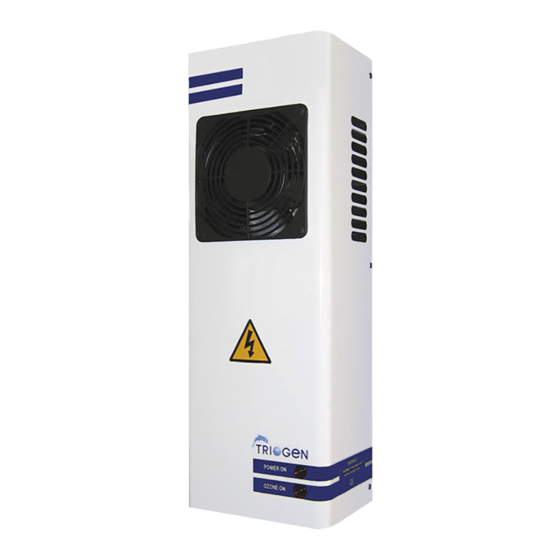
ELECTRICAL INFORMATION SYMBOLS: The lightning flash with arrowhead symbol is to alert the user to the presence of uninsulated “dangerous voltage” within the product enclosure that may be of sufficient magnitude to constitute risk of electric shock to persons. The warning label is to instruct service personnel to disconnect the mains supply before removing the front cover. -
Page 6: Description Of Equipment
Normal atmospheric air can be used as the feed gas, or pre-dried air supplied by a Triogen compact air dryer, either of which is drawn through the ozone generator under vacuum which is created by a water driven venturi injector. -
Page 7: Vacuum Induction System
THE VACUUM INDUCTION SYSTEM The ozone induction system is comprised of an air to water venturi injector which is driven by a water booster pump. The booster pump takes its supply from the filtered water return pipe to the pool and increases the pressure of the water that then passes through the venturi injector. -
Page 8: Installation Of Equipment
INSTALLATION OF EQUIPMENT The installation of the equipment should only be carried out by engineers who are trained in fitting standard pool filtration equipment. BOOSTER PUMP & INJECTOR The injector booster pump suction pipe should be installed as close as possible to the main pool water return line. -
Page 9: Air Dryer
OZONE GENERATOR (CONT’D) After mounting, the ozone generator air outlet should be connected to the side connection of the water trap assembly utilising the 8mm O.D. flexible tubing supplied with the unit and supported at 300mm centres to prevent the tubing from kinking under it’s own weight, particularly at the side connection to the water trap. -
Page 10: Contact / Degassing System
Fill the water trap pot to with water to 25mm from the top. NOTE: It is the responsibility of the user to ensure that the correct level of activated carbon is maintained. Spare activated carbon can be purchased in 2kg packs from Triogen or an appointed agent. -
Page 11: Ozone Generator Mounting Detail
OZONE GENERATOR WALL MOUNTING DETAIL AIR DRYER WALL MOUNTING DETAIL... -
Page 12: T2 Installation Diagram
T2 INSTALLATION DIAGRAM (NO CONTACT / DEGASSER) T2 INSTALLATION DIAGRAM WITH CONTACT / DEGASSER... -
Page 13: T4 Installation Diagram (Contact)
T4 INSTALLATION DIAGRAM WITH CONTACT / DEGASSER T8 INSTALLATION DIAGRAM WITH CONTACT / DEGASSER... -
Page 14: Contact Degassing Diagram
CONTACT DEGASSING SYSTEM NOTE: THE UNIT IS SUPPLIED WITH 1 1/4” - 1” REDUCERS FOR THE WATER CONNECTIONS TO ALLOW THE USE OF 1” PIPING Should the plantroom be below the level of the pool, the system must run on a 24 hour cycle, as the head of water created could cause a leak through the vent valve and find its way into the plantroom via the waterpot. -
Page 15: Water Trap Diagram
WATER TRAP ASSEMBLY... -
Page 16: Electrical Installation
ELECTRICAL INSTALLATION The electrical installation of the equipment should only be carried out by trained personnel. The ozone generator and dryer should be fitted with mains plugs in accordance with the electrical safety instructions. The mains socket into which the units are to be connected should be of the wall mounted SWITCHED mains outlet type. -
Page 17: Redox Control
REDOX CONTROL Redox control is normally only adopted for spa bath applications where accurate dosing monitoring is required due to the high turnover rate of the spa water and fluctuating bather loads. The normal method adopted when ozone is to be used in conjunction with bromine is to combine the ozone system with a commercial brominator fitted with an electrical solenoid valve on its outlet. -
Page 18: Starting The Ozone System
STARTING THE OZONE SYSTEM The start-up of the ozone system will depend largely on how the system has been installed but the following checks should be carried out: Check that the water trap pot and the degasser drain pot, if fitted, have been filled with water to a level of 25mm from the top of the pots and that all interconnecting tubing is correctly installed. -
Page 19: Operation & Maintenance
Note: It is the responsibility of the user to ensure that the correct level of activated carbon is maintained. Spare activated carbon can be purchased in 2kg packs from Triogen or your local distributor. Maximum output of the generator is attained when the control knob is set to position 10. -
Page 20: Togb2 Generator Parts
TOG B2 GENERATOR PARTS ITEM PART DESCRIPTION REF. TOG B2A POWERBOARD ETR0042 FAN 230V 120mm INPUT VERSION FAN0009 FAN 110V 120mm INPUT VERSION FAN0001 OZONE MODULE END CAP MPP0089 MALE ADAPTOR UNION 8mm - 1/8" ST.ST. MPM0072 UNION SEAL RING 1/8"... -
Page 21: Tadb1 Air Dryer Parts
TAD B1 AIR DRYER PARTS ITEM PART DESCRIPTION REF. PROGRAMMABLE RELAY EMC0208 MAIN POWER FILTER SOCKET EMC0165 3 PORT SOLENOID VALVE 230V ESV0026 3 PORT SOLENOID VALVE 110V ESV0027 PURGE PUMP 230V MPM0005 PURGE PUMP 110V MPM0004 HEATER ELEMENT 125 WATT 230V HTR0009 HEATER ELEMENT 125 WATT 110V HTR0008... -
Page 22: Warranty
WARRANTY Triogen ozone generators, air dryers and associated equipment are covered by a twelve month warranty period starting from the date of purchase by the end user during which time any failure of the equipment due to defective workmanship or parts will be repaired... - Page 24 Degrémont Technologies-Triogen East Kilbride G75 0YF, Scotland Tel: +44 (0) 135 522 0598 Fax: +44 (0) 135 557 0058...
Need help?
Do you have a question about the TOG B2 and is the answer not in the manual?
Questions and answers