
Related Manuals for VeriFone Commander

Summary of Contents for VeriFone Commander
- Page 1 Commander Site Controller Hardware Installation Guide P/N DOC149-003-01-R Rev. A02...
- Page 3 The information contained herein does not represent a commitment on the part of VeriFone, Inc. Publications are not stocked at the address given above. Requests for VeriFone publications should be made to your VeriFone representative. VeriFone, the VeriFone logo, and Ruby SuperSystem are registered trademarks of VeriFone, Inc.
- Page 4 This is to prevent loss of data and to ensure that the battery pack is fully charged. Important Information Changes or modifications not expressly approved by VeriFone, Inc. could void the user’s authority to operate this equipment. This equipment is not intended to be repaired by the user.
-
Page 5: Table Of Contents
Choosing a Location ....3 Unpacking Commander Site Controller..4 System Requirements ....5 Cables. - Page 6 Commander Site Controller Hardware Installation Guide...
-
Page 7: Introduction
Use of these expansion capabilities will be determined by VeriFone. System peripherals, such as fuel dispensers, dispenser card readers (DCRs), and car wash controllers connect directly to the Commander Site Controller. Commander Console provides additional functionality with four... - Page 8 The Commander Site Controller contains the functionality of a V950 to perform on-site maintenance operations such as backups, upgrades, restores, and reversions to previous software versions. The addition of a router allows the Commander Site Controller, with the functionality of the V950, to: Receive configurations remotely using available Internet ■...
-
Page 9: Choosing A Location
Many sites place the Commander Site Controller under the counter or in the back office. The Commander Site Controller may be mounted on a wall or under a counter using the brackets designed specifically for it. See the optional Commander Site Controller Bracket Kit for complete mounting instructions. -
Page 10: Unpacking Commander Site Controller
Unpacking Commander Site Controller Carefully inspect the Commander Site Controller shipping carton and its contents for any damage that may have occurred during shipment. If an item appears damaged, immediately file a claim with the shipping company or carrier, and notify your VeriFone representative. -
Page 11: System Requirements
This section contains information about the cables and uninterruptible power supply requirements for the Commander Site Controller. Note: The Commander Site Controller must be installed by a VeriFone Authorized Service Contractor (VASC). Cables System-wide devices connect directly to the Commander Site Controller. - Page 12 Commander Site Controller Hardware Installation Guide...
-
Page 13: Commander Site Controller Diagrams
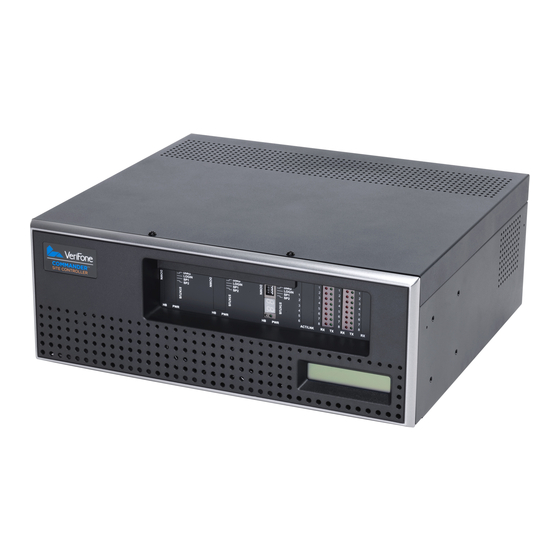
CPU A Device Port LEDs (RX/TX) System Status Display Figure 2: Commander Site Controller - Front Panel System Status Display — The backlit, rectangular display on ■ the front panel of the Commander Site Controller CPU A Indicators and Controls — The indicators and controls ■... -
Page 14: Cpu A Indicators And Controls
Reset Switch — For emergency use only and should never be ■ touched unless instructed by the VeriFone Technical Support Center. Service Console Port — This port is for use by a VeriFone ■ Authorized Service Contractor. It connects the PC/Laptop to the Commander Site Controller. The connection communicates at 19200 bps 8N1. -
Page 15: Cpu A Device Port Leds (Rx/Tx)
Device Port LEDs for A1 Serial Ports for A3 Serial Ports) Figure 4:Transmit/Receive Indicators for CPU A Serial Ports Device Port LEDs (RX/TX) — Shows the status of Commander ■ Site Controller software polling of peripherals connected at the rear panel through the Device Port Banks A1 and A2. Red ON = receive data, Green ON = transmit data. -
Page 16: Rear Panel
USB Port Power Ethernet Port Connector Figure 5:Commander Site Controller - Rear Panel Device Ports CPU A — Serial Port Connections for CPU A, ■ Banks A1 and A2 Activity LEDS for CPU A — LEDs flicker to show LAN activity. -
Page 17: Service And Cleaning
Service Do not, under any circumstances attempt to repair, service, or adjust your Commander Site Controller. The Commander Site Controller system is intended to be serviced only by a factory trained technician. If you have any questions related to installation or troubleshooting, the VeriFone Technical Support Center is available for assistance 24 hours a day, 7 days a week, at 888-777-3536. -
Page 18: Cleaning
Remove dust or dirt with a clean, damp cloth and mild soap or detergent. Use a cloth dampened with alcohol for more stubborn stains. Caution: Never use paint thinner, trichloroethylene, or ketone- based solvents to clean this equipment or cabling as they may deteriorate plastic parts. Commander Site Controller Hardware Installation Guide... -
Page 19: Specifications And Parts
IEC 1000 4-2 (10 KV) Temperature Operating: 32 to 104° F (0 to 40° C) Non-operating: -40 to 158° F (–40 to 70° C) Humidity Operating 15% to 95% relative humidity at 40° C (non-condensing) Commander Site Controller Hardware Installation Guide... -
Page 20: Parts List
Parts List Included Parts List VFI P/N Description M149-101-00-NAA Commander™ Site Controller CBL149-002-01-R Cable, Power Cord left Angle Commander Site Controller Optional Parts List VFI P/N Description 13836-XX Cable Shielded, RS-232 13976-01 DCR Converter Commander Site Controller Hardware Installation Guide...
Need help?
Do you have a question about the Commander and is the answer not in the manual?
Questions and answers