Table of Contents
Advertisement
Advertisement
Table of Contents

Related Manuals for ATEQ D620


Summary of Contents for ATEQ D620
- Page 1 ATEQ D620 Quick Start Guide...
-
Page 2: Table Of Contents
2 / 03 Safety advisory / Warranty Good practices and safety instructions Air quality requirements Preamble ATEQ D620, a universal flow meter Flow rate test Principle of a cycle Your ATEQ D620 Front panel Connectors on the back panel (with all options) - Page 3 User adjustments Options of the menus 3 / 03 Specifications Characteristics D620.388.00_QS_UK_01...
- Page 4 ATEQ - Measurement Solution, Global Leader. 4 / 42 ATEQ info@ateq.com T.: +33 1 30 80 1020 15, rue des Dames, Z.I. ateq.com F.: +33 1 30 54 1100 78340 LES CLAYES-SOUS-BOIS FRANCE ATEQ K.K. info@ateq.co.jp T.: +81 566-84-4670 3 – 41 ATEQ Building, Ikehata ateq.co.jp...
-
Page 5: Safety Advisory / Warranty
Recommendations for the test environment Keep the test area as clean as possible. Recommendations for operators ATEQ recommends that the operators who use the devices have training and a level of qualification that correspond to the job to perform. General recommendations —... -
Page 6: Air Quality Requirements
For this purpose we strongly recommend that a suitable airtight filter is installed between the part under test and the instrument. ATEQ recommends the following characteristics for the air supplied into the device. Air characteristics ISO standard 8573 class Grain size and concentration 0.1 μm and 0.1 mg/m3... -
Page 7: Preamble
Preamble 7 / 42 ATEQ D620, A UNIVERSAL FLOW METER ATEQ D620 is a universal flow meter that measures flow rates through parts to test. ATEQ D620 can memorise 128 different test programs. D620.388.00_QS_UK_01... -
Page 8: Flow Rate Test
FLOW RATE TEST The ATEQ D6 series can do direct or indirect measurements. In both cases, the flow meter can also work in depressurization (option). 8 / 42 Measurement principle When the fluid (gas) enters the device 1, it moves through a calibrated flow tube 2 which causes a drop in pressure. - Page 9 Depending on the part type, it may be possible to use a bell (ex: shower head where it is impossible to recover the flow other than through the use of a bell). This method can only be used if the recovery of the flow is easy. D620.388.00_QS_UK_01...
-
Page 10: Principle Of A Cycle
An additional Pressure auto zero phase 0 can be placed at the start or at the end of a cycle, depending on the requirement of the operator. Flow rate Time Cycle start Cycle end Pressure auto zero phase Fill phase Stabilization phase Test Dumping D620.388.00_QS_UK_01... -
Page 11: Your Ateq D620
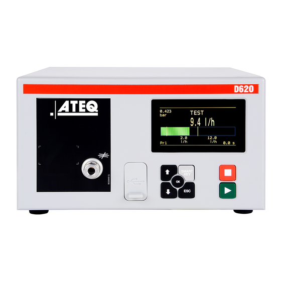
Your ATEQ D620 11 / 42 FRONT PANEL The user interface is located on the front panel. Display Cycle keys Navigation keys USB connectors For more information, refer to User interface. D620.388.00_QS_UK_01... -
Page 12: Connectors On The Back Panel (With All Options)
CONNECTORS ON THE BACK PANEL (WITH ALL OPTIONS) 12 / 42 D620.388.00_QS_UK_01... - Page 13 Connector for 24 V DC - 2 A or 100 / 240 V AC power supply (according option provided) USB (not operational) Dry contact input for ERD test mode (option) Fieldbus connector Network (not operational) * These connectors are not operational. They are provided for future development of our devices. D620.388.00_QS_UK_01...
-
Page 14: Power Supply Connectors
The device can also be connected to a 24 V DC - 2 A power supply through J11 connector on the relay board. Pin number Signal + 24 V DC + 24 V DC Ground: 0 V Apply 24 V DC to the pin 2 or 4. D620.388.00_QS_UK_01... -
Page 15: Digital Links
Do not use a cable longer than 2 m. Push the rubber cover 1 slightly forward for an easy access to USB connectors 2 and 3. Only use this connection for temporary communication. Connection to a PC cannot be used permanently because the communication can be disconnected by the PC. D620.388.00_QS_UK_01... - Page 16 DGND (logic ground) VP (supply) Not used Data line B Not used Devicenet connectors (J5) (J6) (option) M12 type connector - 5 pins male connector (J5) (Devicenet input) For connection to others ATEQ devices. Pin number Signal Drain CAN_H CAN_L D620.388.00_QS_UK_01...
- Page 17 M12 type connector - 5 pins female connector (J6) (Devicenet output) For connection to others ATEQ devices. 17 / 42 Pin number Signal Drain CAN_H CAN_L Profinet connectors (J5 + J6) (option) M12 D coded type connector - 4 pins female connector (J5 + J6)
-
Page 18: Digital Inputs/Outputs
Inputs default mode is PNP. NPN mode is available on request. Relay board connector (J11) (option) Characteristics — Inputs Activation: + 24 V DC. • — Outputs Dry contacts • 60 V AC / DC max - 200 mA max. • D620.388.00_QS_UK_01... - Page 19 The J10 connector is an extension of the J11 connector that enables the selection of 128 programs. Characteristics — Inputs Activation: + 24 V DC. • Pin number Inputs/outputs Description Input 8 Program selection from 33 to 64 (programmable input) Input 9 Program selection from 65 to 128 (programmable input) D620.388.00_QS_UK_01...
- Page 20 Pin 2 (input 3) (input 4) (input 53) (input 6) (input 7) (input 8) (input 9) 17 to 32 33 to 64 65 to 128 * X is equal to 0 or 1 in function of the program number. D620.388.00_QS_UK_01...
- Page 21 Common (outputs 4, 5, 6) Output 4 Open collector Output 5 Open collector Output 6 Open collector Input 1 Programmable input Input 2 Programmable input Input 3 Programmable input Input 4 Programmable input Input 5 Programmable input Ground Input 6 Programmable input Ground D620.388.00_QS_UK_01...
-
Page 22: Pneumatic Connectors
22 / 42 Pneumatic supply The pneumatic supply has to meet specific requirements recommended by ATEQ. Refer to Good practices and safety instructions section. A specific filter may be necessary. The air is supplied via the filter located on the back panel of the device. - Page 23 Test connector The test connector is used to connect the device to the test to part for both direct and indirect modes. Metallic fitting diameter options (in mm): — 4/6 — 6/8 — 8/10 — 15 — 20 — 25. D620.388.00_QS_UK_01...
- Page 24 This connector can be used as regulator output in indirect mode, for bypass option or external capillary option. Instant fitting: 8, 10 or 12 mm diameter for 1 MPa range maximum. Metallic fitting: 4/6 mm or 6/8 mm diameter for 2 MPa range (indirect mode). D620.388.00_QS_UK_01...
- Page 25 25 / 42 ATM 4 mm connector This connector has to be left free to the atmosphere. Instant fitting: 4 mm diameter. ATM 6 mm connector This connector has to be left free to the atmosphere. Instant fitting: 6 mm diameter. D620.388.00_QS_UK_01...
-
Page 26: Pneumatics Configuration
Connection of the part under test to the atmosphere (ATM) 4 to 1 Connection of the test to part to P connector (external back pressure option) 5 to ATM Connector left free to the atmosphere 6 to ATM Connector left free to the atmosphere D620.388.00_QS_UK_01... - Page 27 Connection of the air supply to the valve pilot input (0.6 MPa) 2 to 3 Connection of the test output to the part under test (direct mode option) 3 to ATM Connection of the part under test to the atmosphere (ATM) D620.388.00_QS_UK_01...
- Page 28 4 to 3 Connection of the part to the test input (indirect mode option) 4 to 1 Connection of the test to part (regulator side) to P connector (external back pressure option) 6 to ATM Connector left free to the atmosphere D620.388.00_QS_UK_01...
- Page 29 Connection of the regulator output to the part under test 3 to 2 Connection of the part to the test input (indirect mode option) 5 to ATM Connector left free to the atmosphere Air supply to 6 Connection of the air supply to the valves pilot input (0.6 MPa) D620.388.00_QS_UK_01...
- Page 30 Connection of the part to the test input (indirect mode option) 5 to ATM Connector left free to the atmosphere Air supply to 6 Connection of the air supply to the regulator input (instrument pressure range + 0.1 to 0.2 MPa) D620.388.00_QS_UK_01...
-
Page 31: User Interface
The cycle keys are used to start and to stop a measurement cycle. Name Function Start On the Program screen, starts a measurement cycle and opens the Measurement cycle screen. Reset Stops the measurement cycle in progress and returns to the Program screen. D620.388.00_QS_UK_01... -
Page 32: Display
Use the Program screen to select a test program. Current program name (here NAME) NAME Current program number (here 001) Pr 001 Test type (here DIRECT FLOW) DIRECT FLOW Access at startup of the device or by pressing several times Esc D620.388.00_QS_UK_01... - Page 33 Specific procedures necessary to ensure the proper operation of specific measurement cycles (for example, adjustment of a pressure regulator). PARAMETERS Parameters of the test programs. CONFIGURATION General configuration of the device. SERVICE Maintenance of the device. RESULTS Test results, backup and display options. USB connection functions (backup, restore). D620.388.00_QS_UK_01...
-
Page 34: Starting Up
SELECTING A PROGRAM NUMBER 2. Select the program to configure and press A list of the available measurement types is displayed: PARAM/TYPE DIRECT FLOW — DIRECT FLOW type INDIRECT OPERATOR — INDIRECT type QUICK TEST — OPERATOR type — QUICK TEST type. D620.388.00_QS_UK_01... -
Page 35: Modifying A Parameter
0.0 s TEST TIME 2.0 s DUMP TIME 0.0 s Press. UNIT Max FILL 0.000 3. Repeat these steps until all parameters are set. 4. To return to the MAIN MENU screen, press Esc as many times as necessary. D620.388.00_QS_UK_01... -
Page 36: Selecting A Program
During the measurement cycle, you may press to access the MAIN MENU screen and set parameters for a next measurement cycle. STOPPING A CYCLE 2. Press Reset to immediately stop the current measurement cycle and return to the Program screen. D620.388.00_QS_UK_01... - Page 37 Auto zero cycle on the piezo sensor TO START SPECIAL CYCLES... 1. On the SPECIAL CYCLE MENU screen, select a cycle, and press to validate. 2. Press Start to execute the cycle. 3. To stop the current cycle press Reset D620.388.00_QS_UK_01...
- Page 38 Buzzer activation configuration CODE READER Bar code reader Bar code configuration DISPLAY MODE Display Mode Flow measurement resolution END OF CYCLE End of cycle Several automatism case depending on fail part management FILL MODE Fill types Special filling methods D620.388.00_QS_UK_01...
- Page 39 UNITS Units Access to International System or American or Custom Units VALVE CODES Valve codes Available outputs for external automatism CONFIGURATION menu Use this menu to configure your ATEQ device. GU G MAIN /CONFIGURATION LANGUAGE PNEUMATIC AUTOMATISM SECURITY MISCELLANEOUS Label...
- Page 40 DEVICE INFOS Device information Information about the device, program version, built in components etc. SERVICE CYCLES Special service cycles Allows to display more special cycles to carry out device internal tests RESET PARA Parameters reset Reset to factory configuration D620.388.00_QS_UK_01...
- Page 41 This section describes save and restore parameters on an external USB device. Sa e pa a e e s MENU /USB Save parameters Restore parameters Label Description Save parameters Save parameters on an external USB memory device for later restoration Restore parameters Restore parameters from an external USB memory device D620.388.00_QS_UK_01...
- Page 42 +5 °C to + 45 °C (+ 41 °F to 113 °F) Storage temperature 0 °C to +60 °C (32 °F to 140 °F) Operation altitude Up to 2000 m (6500 ft) Relative humidity 80 % at 31 °C (87 °F) and 50 % at 40 °C (104 °F) D620.388.00_QS_UK_01...
Need help?
Do you have a question about the D620 and is the answer not in the manual?
Questions and answers