Table of Contents
Advertisement
Quick Links
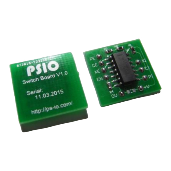
PSIO
Switch Board Installation Guide
Revision 1.0
PlayStation Mainboard [PU-7]
PlayStation is a registered trademark of Sony Computer Entertainment Inc.
PlayStation is Copyright © 1994 Sony Computer Entertainment Inc.
PlayStation
,
,
"DUAL SHOCK" and "PSone" are registered trademarks of Sony Computer Entertainment Inc.
.
PSIO (PlayStation Input Output) is in no way affiliated with Sony Computer Entertainment Inc.
By running PSIO, you agree not to hold us responsible or made liable for any damage to your console.
The user of PSIO assumes full responsibility ensuring its use in accordance with local and federal laws. The software and hardware is
provided "as-is", without any express, implied warranty or guarantee.
"PSIO" is Copyright © 2010-2016 Cybdyn Systems. All Rights Reserved.
1
PSIOSB08052016-PU7
Advertisement
Table of Contents

Related Manuals for Sony PSIO


Summary of Contents for Sony PSIO
- Page 1 By running PSIO, you agree not to hold us responsible or made liable for any damage to your console. The user of PSIO assumes full responsibility ensuring its use in accordance with local and federal laws. The software and hardware is provided "as-is", without any express, implied warranty or guarantee.
- Page 2 This guide is by no means intended for beginners in soldering or electronics. We will NOT be held responsible for any damage to your PlayStation console, or PSIO cartridge. By continuing with this installation document, you must be competent with a soldering iron and know how to cut traces on mainboards.
- Page 3 [1-1: Information] The Switch Board is required in order for PSIO to work correctly. The reason behind it is that Sony never provided direct access to the CD-ROM CPU on the Parallel I/O bus. In our case, access to the CDDA and XA interrupt lines.
- Page 4 Next, begin removing the rest of the screws holding the mainboard to the bottom half of the plastic case. Keep in mind that when reassembling your console that the screws go back in a certain method as some are left blank for the steel chassis to mount though. Once you have the board out of the console, flip it over to show the bottom layer of the PCB (as seen in the image below).
- Page 5 The next stage is to cut a trace on the Parallel Port. It is known as Pin 5, and it is a Ground pin, but it must be used instead for the Switch Boards “EN” (Enable) line. Cut through the marked point in red to isolate Pin 5. Solder Pin 5 to the “EN”...
- Page 6 The next step is to solder the “CD MECH INT” and “CD MECH CS” lines. Note that there are no trace cuts in this photo. You can see the points marked in yellow for where to solder. PSIOSB08052016-PU7...
- Page 7 The next two trace cuts are more difficult. They are known as the “CPU INT” and “CD MECH CS” lines (marked in red). They might take you a while at first to locate on the mainboard, but take your time and don’t rush.
- Page 8 Cut the ‘CPU CS’ trace where the red line is placed. The outlined areas marked in green are where you solder. However, the soldermask on the ‘CPU CS’ via must be carefully scraped away to expose the copper. The ‘CPU INT’ has a pad conveniently placed and does not require the soldermask to be scraped on its via.
- Page 9 The next two (2) pins to solder are pins 65 and 31 on the parallel port. There are no trace cuts needed in this step. Pin 65 goes to “PE” on the Switch Board. Pin 31 goes to “PI” on the Switch Board. PSIOSB08052016-PU7...
- Page 10 Lastly, the power connections are required. The first one is the 3.3V (3V3) rail. PSIOSB08052016-PU7...
- Page 11 And secondly, the “Ground (Gnd)” connection. PSIOSB08052016-PU7...
- Page 12 Congratulations! You have successfully modified your PlayStation with a Switch Board. This is what your installation should look like. PSIOSB08052016-PU7...
- Page 13 When booting with the PSIO cartridge however, ensure that an SD Card with “MENU.SYS” is present, otherwise you will have no way of seeing a visual output from your PSIO cartridge indicating that it is in fact booting and working.
Need help?
Do you have a question about the PSIO and is the answer not in the manual?
Questions and answers