
Summary of Contents for Eelink TK419 Series
- Page 1 4G LTE FDD GNSSTRACKER For Vehicle < > GPS+GSM+WCDMA+LTE FDD+SOS/Battery/iButton/BLE User Manual MODEL:TK419-S/B/I/T/BLE Professional Tracking System...
-
Page 2: Table Of Contents
CATLOG Ⅰ. Product Features ......5 Ⅱ. Components and Accessories ..7 Ⅲ. SIM card Installation .....9 Ⅳ. Device Installation ...... 10 4.1 Install Device......10 4.2 Device Wiring Definition..11 4.3 Relay Wiring......14 Ⅴ. Power On / Off ......15 5.1 Power On......15 5.2 LED Indicators......15 5.3 Power Off......16 Ⅵ. - Page 3 7.2 Vibration Alarm....17 7.3 Shock Alarm......18 7.4 Speed Alarm......18 7.5 Shift Alarm......19 7.6 Geo-fence Alarm....19 7.7 Power Disconnect Alarm..19 7.8 Low Battery Alarm....19 Ⅷ. Device Setting......20 Ⅸ. Trouble shooting......20 9.1 Cannot connect platform..20 9.2 Offline Status......20 9.3 No Positioned......21 9.4 Position Drift......22 9.5 Commands Receiving...
- Page 4 Welcome to use our device, please read this manual carefully to install and operate device exactly. This user manual is for reference only. If some contents and operation steps are inconsistent with those for the actual product, the latter will prevail. With TK419 GNSS Tracker, we can monitor your vehicle by GNSS satellite positioning system, GPRS/WCDMA/LTE FDD network...
-
Page 5: Ⅰ. Product Features
■ GEO-fence alarm, speed & shift alarm. ■ Relay to cut engine, auto cut engine when over speed and recover when normal speed. ■ EELINK protocol 2.0, Firmware OTA ■ USB connect with PC to configure device ■ Waterproof level IP65... - Page 6 Basic Specifications Voltage 12/ 24/ 36/ 48/ 60/ 72 VDC GPRS(500mA);WCDMA(700mA); Work Current LTE(800mA) Standby Current Power off(20uA);Sleep(3mA);Idel(22mA) Satellite Accuracy 5-15m LBS Accuracy >100m GNSSBand 1575MHz GSM Band B2/B3/B5/B8 B1/B2/B5/B8 WCDMA Band FDD(B1/B2/B3/B4/B5/B7/B8 LTE Band /B28); TDD(B40) Working Temperature -20℃~75℃; 20%~90% RH &...
-
Page 7: Ⅱ. Components And Accessories
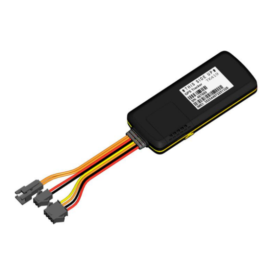
Ⅱ. Components and Accessories ■ Components -Top Front- (Towards sky) -Bottom - ■ Accessories Relay for remotely cut engine, SOS button used for sos help, External battery used for power supplier, iButton can be used for interactive functions such as driver's identification;Temperature sensor used monitoring temperature data;... - Page 8 Power Cable(Default) Relay PIN4(Optional) SOS PIN7/8(Default Optional) iButton PIN7/8(Optional) Bluetooth PIN 5/6/7/8(Optional) BEACON(Optional) External Battery PIN 7/8(Optional)
-
Page 9: Ⅲ. Sim Card Installation
Ⅲ. SIM Card Installation Open the packing case, check if device is OK and accessories are intact, You need a suitable SIM card for using device, contact your dealer if any question; Open SIM Card cover Put SIM Card and waterproof rubber... -
Page 10: Ⅳ. Device Installation
Press cover and close Note: ●Please cut off the power before installing or uninstalling SIM card. ●SIM card should have GPRS/WCDMA/LTE function, open it’s network through operator. ●SIM card should open Caller Identification function for telephone querying. ●If you enable the PIN code of the SIM card, please use your mobile phone to disable it. -
Page 11: Device Wiring Definition
4.1.2 Installation Notice ●Hide device properly inside the car body in order to avoid damages. ●Keep device away from RF emission sources such as backing radar, car burglar alarm and other vehicle mounted communication devices. ●Suggest to use wide strong double-sided adhesive sponge to fix it, or use cable ties and other liable methods to fix it. - Page 13 Total schematic wiring device 4.2.1 Power cables and interface The standard input voltage of device is 9V-72VDC, so please choose the our original power cables, the red cable is positive and the black cable is negative; Please ground negative pole separately or ground it to ground connection, not to any other ground.
-
Page 14: Relay Wiring
power, then the position server think that the vehicle is always ignited. Connect the 4# cable (yellow cable) to the 85 device(with small yellow cable) of the relay. Use cable ties to fix the relay to waterproof place, or use plastic bags cover the relay. -
Page 15: Ⅴ. Power On / Off
Notice: Be sure the voltage of the vehicle power should match up to the working voltage of relay, or relay maybe damaged. Ⅴ. Power On / Off 5.1 Power on Power on: insert a valid SIM card and wire all the cables, device will power on. -
Page 16: Power Off
LED(indicates GSM/WCDMA/LTE state) Searching for Fast blinking GSM/LTE network GSM/LTE works Slow blinking normally Blue LED(indicates GNSSstate) Searching Fast blinking GNSSSatellites Slow blinking GNSSworks normally 5.3 Power off Disconnect the external power and take off SIM card, after a while device will shut down. Ⅵ. -
Page 17: Inquiry By Sms
your dealer to get installation package. 6.2 Inquiry by SMS You can write a positioning SMS sending to device to inquiry position, device will reply position SMS or map link. The SMS commands please refer to the Operation Commands 2.0 6.3 Cut Engine/Restore 6.3.1 Cut off oil circuits Server(GPRS/WCDMA/LTE) or Manager number... -
Page 18: Vibration Alarm
seconds. Note: SOS button must be installed (optional accessory), and SOS administrator number must be set. When the SOS alarm occurs, device will dial the set SOS administrator number 3 times until getting through. Note: When above alarm occurs, Device will send alarm to service platform, meanwhile send a SMS message to administrator number if this number was set. -
Page 19: Shift Alarm
value, also an over-speed value to cut engine 7.5 Shift Alarm Conditions: When vehicle occur a setting shift in the Flameout status. Note: Only valid in flameout state and vehicle occur a setting shift distance. 7.6 Geo-fence Alarm Conditions: when the vehicle entry / exit / across the Geo-fence. -
Page 20: Ⅷ. Device Setting
Ⅷ. Device Setting Please refer to <Operation Commands 2.0> Ⅸ. Trouble shooting 9.1 Cannot connect platform device is never online on the position server when installed at the first time. Please check device: 1) If power cables are wired correctly? Pay attention to not connect them to controlling cables of vehicle. -
Page 21: No Positioned
GSM/WCDMA/LTE signal. 3)Check if one device or all devices are offline in the area . If all devices are offline, you should ask operator If network is OK. 4)Check if SIM card has enough balance. 5)If device becomes offline on the last day of one month, please check GPRS is closed or not. -
Page 22: Position Drift
9.4 Position drift Serious position drift will be found in places where GNSS signal is poor. Please drive the vehicle to the open places. 9.5 Commands receiving abnormally 1)Check the commands format. 2)Check if the vehicle is in the places where there is GSM signal. -
Page 23: Warranty Period
10.2 Warranty period Since the date of purchase, passive waste host has one year warranty. 10.3 After sales Any of the following circumstances not covered by the warranty, but may be appropriate to pay repair: 1)More than the warranty period. 2)Unauthorized removal or repair damaged.
Need help?
Do you have a question about the TK419 Series and is the answer not in the manual?
Questions and answers