Table of Contents
Advertisement
Quick Links
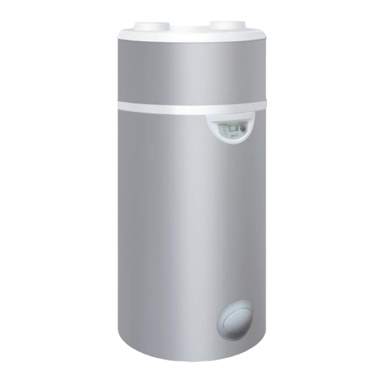
Edel
Heat pump water heater
using exterior or non-heated ambient air
Installation manual
Manual ref. : 1897105
Edition n° 20.029
The information contained in this document is non-contractual. Auer reserves the right to modify the technical specifications or characteristics of any of their appliances without prior notice. .
AIR
Necessary technical data
-in appendix-
Edel 200 AIR D/2
Ref. 353420
Edel 270 AIR D/2
Ref. 353430
Made in
FRANCE
Advertisement
Table of Contents
Troubleshooting

Related Manuals for auer Edel AIR Series


Summary of Contents for auer Edel AIR Series
- Page 1 Necessary technical data Manual ref. : 1897105 -in appendix- Edition n° 20.029 The information contained in this document is non-contractual. Auer reserves the right to modify the technical specifications or characteristics of any of their appliances without prior notice. .
-
Page 2: Table Of Contents
CONTENTS TABLE DES MATIÈRES 5.9.3 -Locking the keyboard ....................14 1 - SAFETY ............3 5.9.4 - Resetting parameters ....................15 2- RECOMMENDATIONS ........4 5.9.5 - Read data ........................15 5.9.6 - Counters (meters) ....................15 2.1 - Storage ..........................4 6 - MAINTENANCE AND TROUBLESHOOTING 16 2.2 - Transport ......................... -
Page 3: Safety
Preserving these documents Rules and regulations (directives, laws, and standards) • This manual and all other relevant documents should be given to the system user. Once the appliance is installed and switched The system user should keep these manuals for future reference. on, all decrees, directives, technical rules, safety measures and standards, must be 1 - SAFETY... -
Page 4: 2- Recommendations
WARNING 2- RECOMMENDATIONS Do not use any methods to accelerate the defrosting or cleaning process other than those recommended by the manufacturer. The appliance must be stored in a room which The appliance can only function when filled does not contain a perpetual flame or other with water. -
Page 5: Contents Of Packaging
3 - PRESENTATION If tipped, the centre of gravity will shift towards the top: handle with care. 3.1 - Dimensions 3.1.1 - 200 L Heat pump water heater Risk of tipping Do not drop or lower suddenly Once the heat pump water heater is installed in its definitive position, it is imperative to wait 15 minutes before it is turned on. -
Page 6: Technical Specifications And Performances
4 - INSTALLATION 3.2 - Technical specifications and performances 4.1- Placement and positioning EDEL AIR EDEL AIR 200L D/2 270L D/2 4.1.1- Placement choice Heat pump performance Nominal volume INSTALLATION PRECAUTIONS : Max. input power 1900 1900 • The appliance must not be installed near a Air temperature range -7 to +35 -7 to +35... -
Page 7: Air Connection
heat pump water heater • The floor must be able to support the weight of the heat pump must be connected using insulated water heater (weight of the heat pump water heater filled with air ducts with an interior diameter of 160mm. water 200 L/ 270 L= 260 kg / 335 kg). -
Page 8: Condensates Drainage
1. Stop valve 2. Pressure reducing valve 3. Check- valve Domestic hot water (DHW) 4. Insulating dielectric sleeve (not supplied) Flexible condensate 5. Pressure relief membrane valve (not drainage tube supplied) 7. Run-off siphon 8. Domestic water expansion vessel 9. Thermostatic mixing valve 10. -
Page 9: Electrical Connections
4.5 - Electrical connections Do not connect the heat pump water heater to wiring from an older water heater using the peak/off-peak hours contact. The heat pump water heater must always be connected to a power supply. Peak/off-peak control can be managed through programming or though an independent cable. -
Page 10: Connection To The Photovoltaic Function (Pv)
4.5.1.4 - Connection to the photovoltaic function (PV) This function enables the appliance to operate in auto- Energy manager production mode, which means that it will use the dry contact energy produced by the PV function to supply the heat pump as well as the electrical back-up, and to heat the water in the tank. -
Page 11: Setting The Language
5.4 - Setting the desired water 5.2 - Setting the language temperature The language must be selected when the appliance is turned 5.4.1 - PV mode inactive on for the first time. Turn the dial to the left and select «English». The water temperature is adjustable from 30°C to 65°C. -
Page 12: Holiday/Temporary Standby Mode
5.5 - Holiday/temporary standby mode 5.6 - BOOST function (for occasional use and guaranteed comfort) h ol i d ay « » mode puts the appliance on standby while the frost protection mode remains active. This function can be The « boost »... -
Page 13: Installer Menu
7. Turn the dial to select the primary function: 5.9 - Installer menu - Menu → INST. MENU → MODE PV → PRIORITY It may be necessary to adjust certain temperature settings to • Yes: the signals from connectors 1 and 2 take precedence over heat pump water heater, eco and frost protection modes. -
Page 14: Fan Mode
sh eddi ng she dding • If a cycle is interrupted by a period where the back-up is not allowed to run (electricity provider signal or programmed time slots) it will relaunch during the next authorised period. •No anti-legionellosis cycle except when returning from holidays Select the mode and after a frost protection period of more than 3 days. -
Page 15: Resetting Parameters
AUTO = To lock menu access with temporary unlocking (60 5.9.5 - Read data seconds) press for 3 seconds. The «READ DATA» menu shows you, in real time, the information given by the sensors. In the «Installer» menu, turn the dial to «display». u n l o c k . -
Page 16: Maintenance And Troubleshooting
6 - MAINTENANCE AND .../... TROUBLESHOOTING → The refrigerant circuit containing flammable refrigerant complies with national gas regulations. In order to maintain efficiency and improve durability → In case of operating on the refrigerant circuit: it is advised that an annual maintenance check be carried out by a qualified professional. -
Page 17: Troubleshooting
6.5 - Drainage 6.4 - Troubleshooting 1) Switch off the power supply. • The heat pump is not working 2) Shut off the cold water inlet valve on the safety group. Check that: • The desired water temperature is higher than the temperature 3) Open the hot water valves. -
Page 18: List Of Spare Parts
6.7 - List of spare parts Rep. 200L 270L Description Regulation / display B1244096 B1244096 C3S electronic circuit board controller B4992570 B4992570 Control panel display B1244576 B1244576 Temperature sensor lg460mm B1244577 Temperature sensor lg00mm B1244575 Temperature sensor lg1200mm B4993072 B4993072 Defrosting sensor kit Electrical B4993826 B4993826... -
Page 19: Error Message Codes: Errors, Solutions And Operating In Case Of Error
6.8 - Error message codes: errors, solutions and operating in case of error N.B. : Errors can be dismissed by briefly pressing the dial (manual reset) Temporary operation measures Display Error Probable causes Solutions while waiting for the problem to be solved •Voltage too high on electrical network... - Page 20 Temporary operation measures Display Error Probable causes Solutions while waiting for problem to be solved •The air and defrosting sensors are inverted on the electronics board •The defrosting and water sensors are inverted on the electronics •Reposition the temperature •Incorrect temperature sensor board sensors correctly on the main reading...
-
Page 21: Warranty
7.1.2.3 - Installation site 7 - WARRANTY Cases (not limited to) where the warranty is void: • Placing the appliance where it can be subject to frost or other The tank is guaranteed against breakage for a period of five (5) years, adverse weather conditions. -
Page 22: Appendices
8 - APPENDICES 8.1 - Performance statistics 8.1.1 - COP development 8.1.2 - Heating time The performances are measured during a standardised heating This graph represents the heating time for a full tank depending cycle (EN 16147) with cold water at 10°C. on the air and domestic hot water temperatures using the heat This graph represents the development of the COP depending on pump and without a back-up. -
Page 23: Electrical Wiring Diagram
8.2 - Electrical wiring diagram HEAT PUMP WATER HEATER 200 -270L AIR D/2 - installer manual... - Page 24 Spare parts department Industrial and development Tél. : 03 22 61 21 21 - Fax : 03 22 61 33 35 site E-mail : pieces@auer.fr Rue de la République Technical department CS 40029 E-mail : enr@auer.fr 80210 Feuquières-en-Vimeu...
Need help?
Do you have a question about the Edel AIR Series and is the answer not in the manual?
Questions and answers