
Summary of Contents for ROTORCOMP NK 31
- Page 1 Installation and operating manual SCREW COMPRESSOR COMPACT MODULE NK 31 Original operating manual [en] 02/2014...
- Page 2 © Copyright ROTORCOMP VERDICHTER GmbH, 2014 All rights reserved. No duplication, modification or translation beyond the degree permitted by the applicable copyright laws is permitted without prior written approval. The information contained in this document is subject to change without prior notice.
-
Page 3: Table Of Contents
Installation and operating manual - NK 31 Contents Foreword ..........1.1 3.8.1 Standstill ..........3.7 3.8.2 Load condition........3.8 General ..........1.1 Scope ..........1.1 3.8.3 Switching off ........3.8 Change service ........1.1 Intake valve ......... 3.9 3.9.1 Installation position ......3.9 Abbreviations ........ - Page 4 ROTORCOMP VERDICHTER Installation and operating manual - NK 31 Contents Maintenance ........7.1 Safety precautions ......7.1 Oil level ..........7.2 7.2.1 Oil level check via oil filler opening ..7.2 Oil change ........... 7.3 7.3.1 Oil change intervals ......7.3 7.3.2 Oil drain points ........
-
Page 5: Foreword
NK 31. Read this operating manual carefully before com- missioning the NK 31 for the first time in order to ensure proper handling, operation and mainte- nance from the outset. -
Page 6: Purpose
1.5.2 Purpose – Use of unsuitable tools – Failure to use genuine spare parts The NK 31 is a screw compressor compact mod- – Unauthorized modifications to the screw com- ule designed for installation in a compressed-air pressor module and/or its components–... -
Page 7: Safety Precautions
Attention The following safety precautions only refer to the Refers to working and operating processes which NK 31 screw compressor module and not to the must be exactly complied with to prevent damage entire compressor system. to or destruction of parts or all of the system. -
Page 8: Special Symbols
ROTORCOMP VERDICHTER Installation and operating manual - NK 31 2.3.1 Special symbols Do not operate the system without the Warning on a danger point safety device mounted Do not inhale compressed air from this Warning: machine Danger of explosion and/or detonation... -
Page 9: Technical Description
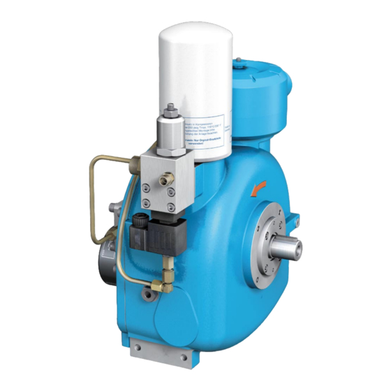
Installation and operating manual - NK 31 Technical Description 3.1 General overview of NK 31 Screw Compressor Compact Module (standard model with electric control unit) 12 11 Figure 3-1 1. Name plate 11. Oil circuit / outlet 2. Intake valve with intake filter unit 12. -
Page 10: Screw Compressor Compact Module (Standard Model With Electric Control Unit)
The flow diagram shows a schematic view of the 3.1 Solenoid valve operating principle and the arrangement of the Screw compressor main components of the NK 31 screw compres- Separator tank with pre-separation sor module with electrical control unit, regardless Fine separator of any other equipment. -
Page 11: Relieved Stating
Installation and operating manual - NK 31 3.3.2 Relieved stating 3.3.4 Switching off During relieved starting a small air quantity is When the system is switched off, the intake already drawn in at a minimum vacuum by the ro- valve 2, operates, supported by spring pressure, tor rotation. -
Page 12: General Overview Of Nk
ROTORCOMP VERDICHTER Installation and operating manual - NK 31 3.4 General overview of NK 31 Screw Compressor Compact Module (standard model with pneumatic control unit) 12 11 Figure 3-3 1. Name plate 11. Oil circuit / outlet 2. Control unit, pneumatic 12. -
Page 13: Screw Compressor Compact Module (Standard Model With Pneumatic Control Unit)
3.1 Proportional control valve The flow diagram shows a schematic view of the (positive) operating principle and the arrangement of the main components of the NK 31 screw compres- 3.2 Impulse-pressure relief valve sor module with pneumatic control unit, regard- 4. Screw compressor less of any other equipment. -
Page 14: Starting
ROTORCOMP VERDICHTER Installation and operating manual - NK 31 3.6.2 Starting 3.6.3 Switching off During start-up, the intake valve 2 already opens When switching off the system, the intake valve 2 at minimum vacuum in the intake chamber of the operates, supported by spring pressure, as an in- screw compressor 4 due to the rotor rotation. -
Page 15: Flow Diagram Of Nk
The flow diagram shows a schematic view of the operating principle and the arrangement of the 6. Minimum pressure valve main components of the NK 31 screw compres- 7. Oil thermostat sor module with pneumatic control unit, regard- 8. Oil filter less of any other equipment. -
Page 16: Load Condition
ROTORCOMP VERDICHTER Installation and operating manual - NK 31 3.8.2 Load condition The rotor rotation produces vacuum in the suc- tion port which opens the untake valve 2. The drawn in air flows via the intake filter 1 through the intake valve 2 directly into the com- pression chamber of the screw compressor 3. -
Page 17: Intake Valve
Installation and operating manual - NK 31 3.9 Intake valve Different control units can be used for various operating modes: The NK 31 is equipped with an integrated intake valve mounted directly on the compressor hous- – the EMC electric control unit or ing. -
Page 18: Intake Air Filter
ROTORCOMP VERDICHTER Installation and operating manual - NK 31 3.10 Intake air filter 3.10.2 Intake filter monitoring • Maintenance indicator, optical (option) • Maintenance indicator, electric (option) The micro air filter elements are recommended as a 1-stage filter with a low filter resistance for standard applications. -
Page 19: Fine Separator
Installation and operating manual - NK 31 3.11 Fine separator 3.11.1 Oil intake non-return valve Figure 3-10 The oil intake non-return valve 1 prevents flood- ing of the fine separator cartridge with oil flow- ing back out of the screw compressor due to the pressure difference in the system when the screw compressor system is switched off. -
Page 20: Fine Separator Cartridge
ROTORCOMP VERDICHTER Installation and operating manual - NK 31 3.11.2 Fine separator cartridge The fine separator cartridge is used to recover the extremely finely distributed residual oil in the form of droplets following the pre-separation. The fine separator cartridge separates virtually the entire residual oil from the compressed air. -
Page 21: Minimum Pressure Valve
Installation and operating manual - NK 31 3.11.3 Minimum pressure valve Figure 3-12 A Minimum pressure valve closed The minimum pressure valve is located on the outlet of the compressor before the air recooler B Minimum pressure valve opened and serves as:... -
Page 22: Air-Oil Circulation Outside Compressor Module
ROTORCOMP VERDICHTER Installation and operating manual - NK 31 3.12 Air-oil circulation outside compressor module Figure 3-13 After the oil-air mixture in the fine separator cartridge has been deoiled, the compressed air flows through the air cooler and from there to the consumer. -
Page 23: Oil Filter
The NK 31 is equipped with an integrated oil the working element (in this case the working thermostat 3. This is located in the basic mod- element must be replaced). -
Page 24: Oil Cooler/Air After-Cooler (Option)
ROTORCOMP VERDICHTER Installation and operating manual - NK 31 3.13 Oil cooler/air after-cooler (option) Warning With air-cooled screw compressor systems the The safety valve must be installed prior to com- circulating oil is cooled down from the compres- missioning. sor outlet temperature to the compressor injec- Operation of the system without a safety valve tion temperature. -
Page 25: Transport
Installation and operating manual - NK 31 Transport 4.1 Delivery and packing The deadlines are as follows: The system is delivered in suitable packing in ac- cordance with the selected shipping method and a) GERMAN FEDERAL RAILWAY: delivery conditions. within 7 days... -
Page 26: Transporting Unpacked System
ROTORCOMP VERDICHTER Installation and operating manual - NK 31 4.3 Transporting unpacked system 4.4 Transport options The screw compressor can be moved with a crane or with a lift truck or forklift truck when fas- tened to a transport pallet. -
Page 27: Installation/Assembly
Installation and operating manual - NK 31 Installation/Assembly 5.1 Connection thread/assembly 5.2 Safety precautions for installation and assembly 5.1.1 Fastening screws Female threads are provided on the NK housing Attention which must be used for fastening. Only suit- able screws with a METRIC THREAD are to be –... -
Page 28: Installation
ROTORCOMP VERDICHTER Installation and operating manual - NK 31 5.3 Installation 5.3.1 Fastening on base frame with screw fitting Attention – The system must be installed at a location at which the ambient air is as cool and clean as possible. -
Page 29: Belt Drive
Installation and operating manual - NK 31 5.4 Belt drive 5.5 Direct drive Improper design and/or installation of the V-belt Attention drive can result in a considerable reduction of he bearing life and/or to breakage of the drive shaft. Offset and angular errors result in damage to... -
Page 30: Air Outlet
ROTORCOMP VERDICHTER Installation and operating manual - NK 31 5.6 Air outlet 5.7 Oil cooling The pressure loss at the air outlet due to air after- Note coolers, fittings, piping, etc.should be as small as possible. The cooler connection lines must be con- nected torque-free to the oil connections. -
Page 31: Commissioning
Installation and operating manual - NK 31 Commissioning 6.1 Preparation for commissioning 6.2 Checking direction of rotation The components of the screw compressor are Direction of rotation: carefully checked and tested at the factory. Standard model rotating to the left (counterclock- These tests ensure that the required perfor- wise) looking at the shaft. -
Page 32: Recommissioning Screw Compressor System
ROTORCOMP VERDICHTER Installation and operating manual - NK 31 6.4 Recommissioning screw compressor system Screw compressor systems switched off, shut- down or stored for longer than three months cannot be put into operation again until after the following measures have been carried out: –... -
Page 33: Maintenance
Installation and operating manual - NK 31 Maintenance 7.1 Safety precautions Warning The owner must ensure that all maintenance, During all maintenance work: assembly and repair work is carried out by au- thorized, qualified, specially trained personnel, ACCIDENT DANGER! which has informed itself sufficiently in advance by studying the operating manual in detail. -
Page 34: Oil Level
ROTORCOMP VERDICHTER Installation and operating manual - NK 31 7.2 Oil level 7.2.1 Oil level check via oil filler opening An important factor for the operating safety of the system is the oil level in the oil reservoir. Warning The oil level check must be carried out before –... -
Page 35: Oil Change
Installation and operating manual - NK 31 7.3.2 Oil drain points Note The system should be at operating temperature The oil filler neck is positioned so that overfilling in this case. of the screw compressor system is not possible. Excess oil runs out of the filler neck again. -
Page 36: Filling With Oil
ROTORCOMP VERDICHTER Installation and operating manual - NK 31 7.3.3 Filling with oil 7.4.2 Oil filter replacement Attention Observe the oil recommendation, see “Lubricants and Operating Materials”. Add oil of the same oil type from the same manufacturer. Switching over to another oil type can require the compressor module to be flushed. -
Page 37: Fine Separator Cartridge
Installation and operating manual - NK 31 7.5 Fine separator cartridge 7.5.2 Replacing fine separator cartridge Warning Rotating, pressurized and hot components, DANGER OF INJURY – The unit parts and oil may be over 80°C/176°F; danger of burns! – Wear personal safety equipment! -
Page 38: Intake Air Filter
ROTORCOMP VERDICHTER Installation and operating manual - NK 31 7.6 Intake air filter • Switch off the system and secure it against unauthorized switch-on. 7.6.1 Maintenance intervals • Screw off the nut 1 and remove the filter cover 2. According to the specifications of the system •... -
Page 39: Maintenance Check Sheet
Installation and operating manual - NK 31 7.7 Maintenance check sheet • Elapsed time meter reading • Replace intake filter • Replace oil filter cartridge • Replace oil fine separator cartridge • Retension V-belts • Replace V-belt set • System repair •... -
Page 40: Maintenance Intervals
Depending on the design of the system, maintenance interval should therefore be specified by the compressor manufacturer. These must be given priority. It is advisable to conclude a maintenance agreement. The following table provides an overview of the reference value for the NK 31 screw com- pressor module. -
Page 41: Lubricants And Operating Materials Maintenance Parts
Installation and operating manual - NK 31 Lubricants and Operating Materials Maintenance Parts 8.1 Lubricants and operating materials Note 8.1.1 Oil recommendation See the information sheet! RC screw compressors must be operated with an oil suitable for special requirements. This oil... -
Page 42: Pressure Dew Point Of Compressed Air
ROTORCOMP VERDICHTER Installation and operating manual - NK 31 Determination of absolute humidity Absolute humidity in intake air [g/m in intake air [g/m Relative humidity 30% 40% 50% 60% 70% 80% 90% 100% 24,7 32,9 41,1 49,4 57,6 65,8 74,0... -
Page 43: Oil Separation
Installation and operating manual - NK 31 8.1.9 Oil separation The fine oil separation becomes poorer in the upper area with an increasing compressor outlet temperature. 8.1.10 Multigrade oil The use of multigrade oils can cause problems in the long run, as „viscosity improvers“ used are destroyed over time. - Page 44 ROTORCOMP VERDICHTER Installation and operating manual - NK 31 [en] 02/2014...
-
Page 45: Technical Data And Tightening Torques
** up to max. 7 bar (g) Note This sheet contains only general technical data for this screw compressor. The corresponding ROTORCOMP performance sheet applies for calculation, design and measure- ment. Technical data on the entire screw compressor system, drive motors, electrical system and accessory components in accordance with the corresponding data sheet of the manufacturer or supplier. -
Page 46: Tightening Torques
ROTORCOMP VERDICHTER Installation and operating manual - NK 31 9.2 Tightening torques Attention The maximum permissible tightening torque for all screw connections may not be exceeded. VDI 2230 Unless otherwise specified, the following torques must be used. Always tighten screws/bolts with a torque wrench. -
Page 47: Troubleshooting
Installation and operating manual - NK 31 10 Troubleshooting Fault Possible cause Remedy See chapter Incorrect direction of Phases reversed Reconnect 2 supply lines rotation System does not start No electricity Check Combistat switches off Check oil level, cooling, due to excessively high... - Page 48 ROTORCOMP VERDICHTER Installation and operating manual - NK 31 Fault Possible cause Remedy See chapter Safety valve blows off Safety valve defective Replace safety valve Fine separator cartridge Replace cartridge 7.5.2 soiled System does not relieve Continuous operation System does not...
- Page 49 Installation and operating manual - NK 31 Fault Possible cause Remedy See chapter Control valve does not Pressure switch, or Check setting close control valve Oil exits through intake Sealing surface on intake Check parts and replace control valve during...
- Page 50 ROTORCOMP VERDICHTER GmbH Industriestraße 9 82110 Germering Germany phone +49 89 72 409 - 0 +49 89 72 409 - 38 info@rotorcomp.de www.rotorcomp.de A Member of BAUER GROUP...
Need help?
Do you have a question about the NK 31 and is the answer not in the manual?
Questions and answers