
Related Manuals for Chiller BOX Vari

Summary of Contents for Chiller BOX Vari
- Page 1 Vari & Vari Pro Installation, Operation, and Maintenance Manual N02118905 Rev. A...
- Page 2 BOX Vari & Vari Pro – Installation, Operation, and Maintenance Manual Chiller Oy will not assume responsibility for any errors or shortcomings that may appear in this document. The end user is responsible for ensuring that the unit operates appropriately and safely. Working with electric components is subject to permission.
-
Page 3: Table Of Contents
N02118905 Rev. A BOX Vari & Vari Pro – Installation, Operation, and Maintenance Manual Contents 1 General ......................4 About this manual ..................4 Guarantee....................4 Inspection of the unit .................5 Related documentation ................5 2 Safety .......................6 General safety instructions ................6 Safety-related signs ..................6 Safety symbols ..................6... -
Page 4: General
Keep the manual for later reference. Guarantee The guarantee for this unit is based on Chiller Oy’s terms of guarantee. The guarantee becomes void, if: • the product is modified or repaired without a written consent from Chiller Oy •... -
Page 5: Inspection Of The Unit
N02118905 Rev. A BOX Vari & Vari Pro – Installation, Operation, and Maintenance Manual Inspection of the unit The units are shipped from the factory as assembled (apart from some accessories), wired, and tested. In some unit models, part of the grille is shipped in a separate package for mounting onto the lower surface of the lowered ceiling after installation. -
Page 6: Safety
N02118905 Rev. A BOX Vari & Vari Pro – Installation, Operation, and Maintenance Manual Safety General safety instructions This unit is designed so that it does not expose people to hazard or risk, provided that: • The unit is installed, operated, and maintained according to the instructions in this manual. - Page 7 N02118905 Rev. A BOX Vari & Vari Pro – Installation, Operation, and Maintenance Manual Prohibited action symbols These symbols are used in warnings and notifications to indicate an action that should not be taken. The prohibited action symbols are shown below.
-
Page 8: Unit Overview
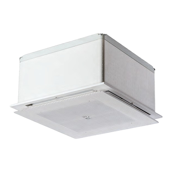
N02118905 Rev. A BOX Vari & Vari Pro – Installation, Operation, and Maintenance Manual Unit overview Introduction of the unit The Box cassette fan coil unit is designed for room air conditioning. The unit is available in two sizes, Box Mono and Box Double. The unit is also available with two automation options, Vari and Vari Pro. -
Page 9: Unit Dimensions
BOX Vari & Vari Pro – Installation, Operation, and Maintenance Manual Unit dimensions The unit comes in two sizes, Box Mono and Box Double. Note! The unit dimensions are given as reference. Chiller Oy reserves the right to make changes to them. Check the actual dimensions from the order documentation. -
Page 10: Automation Options And Control Connections
N02118905 Rev. A BOX Vari & Vari Pro – Installation, Operation, and Maintenance Manual The type plate specifies the following information about the unit: TYPE Unit type Including accessories (18 characters consisting of letters and numbers) SER.NR. Unit serial number... -
Page 11: Vari-Option
N02118905 Rev. A BOX Vari & Vari Pro – Installation, Operation, and Maintenance Manual 3.4.1 Vari-option The automation option Vari has the following properties: • Analogue control (0-10 V and 24 V AC/DC for on/off on all inputs) • Suitable for analogue control from building automation or traditional room controller •... -
Page 12: Vari Pro-Option
N02118905 Rev. A BOX Vari & Vari Pro – Installation, Operation, and Maintenance Manual 3.4.2 Vari Pro-option The automation option Vari Pro has the following properties: • Control with the Vari Pro graphical room controller or directly by Modbus RTU from building management system •... -
Page 13: Installation Of The Unit
N02118905 Rev. A BOX Vari & Vari Pro – Installation, Operation, and Maintenance Manual Installation of the unit General installation instructions CAUTION Only professionally skilled and qualified personnel can install the unit. Note! Always follow local safety regulations when you install, operate, and maintain the unit. -
Page 14: Choosing The Installation Site
N02118905 Rev. A BOX Vari & Vari Pro – Installation, Operation, and Maintenance Manual cover, and remove the external drain pan from the access hatch on the cover. You can also install the unit to the ceiling and attach the pipes and electrical connections without removing the cover. -
Page 15: Mounting The Unit
N02118905 Rev. A BOX Vari & Vari Pro – Installation, Operation, and Maintenance Manual Table 1: Limitations for the BOX installation site Temperatures Min. Max. Indoor air 5 °C (A) 32 °C Water 4 °C (B) 80 °C (C) Ethyl alcohol (35%) 4 °C... - Page 16 N02118905 Rev. A BOX Vari & Vari Pro – Installation, Operation, and Maintenance Manual 1. Open the attachment bracket screws by turning them counterclockwise. 2. Move the attachment brackets from transport position to installation position by pulling them outwards. 3. Secure the attachment brackets by tightening the fastening bolts. Tighten the bolts to 8 Nm.
-
Page 17: Removing The Package Cover
N02118905 Rev. A BOX Vari & Vari Pro – Installation, Operation, and Maintenance Manual 6. Make sure that the lower surface of the unit is at the same level as the lower surface of the lowered ceiling. 7. Make sure that the distance between the unit and the ceiling is at least 20 8. - Page 18 N02118905 Rev. A BOX Vari & Vari Pro – Installation, Operation, and Maintenance Manual Note! Use only the screws included in the unit delivery to fasten the grille. Note! Make sure that the grille is installed firmly against the unit.
-
Page 19: Attaching The Water Connections
N02118905 Rev. A BOX Vari & Vari Pro – Installation, Operation, and Maintenance Manual 2. Box Double: after mounting the unit to the ceiling, attach both parts of the grille into place with screws (16 pcs). The grille is attached to the mounting points of the condensation water basin. -
Page 20: Installing Sewerage For Condensation Water
N02118905 Rev. A BOX Vari & Vari Pro – Installation, Operation, and Maintenance Manual 2. Attach the water connections as shown below. Cooling water inlet Cooling water outlet Hot water inlet Hot water outlet 3. Use flat seal connectors when you attach the water connections. Make sure that the connector material is suitable for the connector type. - Page 21 N02118905 Rev. A BOX Vari & Vari Pro – Installation, Operation, and Maintenance Manual 1. Before you install the sewerage, make sure that a. the sewerage has sufficient inclination of at least 2%. b. the cross-sectional area of the condensation water pipe is sufficient, at least 22 mm.
-
Page 22: Sewerage Without Condensation Water Pump
N02118905 Rev. A BOX Vari & Vari Pro – Installation, Operation, and Maintenance Manual 4.7.1 Sewerage without condensation water pump You can see the location of the outlet set for condensation water in the figure below. 1. Before installation, make sure that the installation site is horizontally sufficiently inclined for sewerage. -
Page 23: Attaching The Electrical Connections
N02118905 Rev. A BOX Vari & Vari Pro – Installation, Operation, and Maintenance Manual 1. Before installation, make sure that the cross-sectional area of the condensation water network is sufficient. 2. Connect the tight connection to the condensation water piping. - Page 24 N02118905 Rev. A BOX Vari & Vari Pro – Installation, Operation, and Maintenance Manual CAUTION When connecting the unit to the circuit, make sure that the connection is done in accordance with local laws and decrees. Note! The unit is available with Vari or Vari Pro equipment. The unit is delivered with model-specific electric diagrams that must be used when doing the electrical connections.
-
Page 25: Installing The External Drain Pan
N02118905 Rev. A BOX Vari & Vari Pro – Installation, Operation, and Maintenance Manual Installing the external drain pan 1. Install the external drain pan by pushing it to the slots on the side of unit. 4.10 Testing the condensation water pump CAUTION Risk of water damage. - Page 26 N02118905 Rev. A BOX Vari & Vari Pro – Installation, Operation, and Maintenance Manual 2. After you have poured the water into the basin, make sure that a. the condensation water pump starts b. the pump moves the water to the condensation sewerage c.
-
Page 27: Operation Of The Unit
N02118905 Rev. A BOX Vari & Vari Pro – Installation, Operation, and Maintenance Manual Operation of the unit Controlling the unit The fan motor of the unit is equipped with a modern EC (electronically commuted) motor. The fan motor is controlled with voltage messages of 0–10 VDC. -
Page 28: Maintenance Of The Unit
N02118905 Rev. A BOX Vari & Vari Pro – Installation, Operation, and Maintenance Manual Maintenance of the unit Maintenance schedule WARNING If you detect water leakage during unit operation, shut down the unit and contact maintenance. For the unit to function properly, you must do the maintenance procedures regularly. -
Page 29: Removing The Filter
N02118905 Rev. A BOX Vari & Vari Pro – Installation, Operation, and Maintenance Manual 1. Open the grille. 2. Clean the grille with a clean, damp cloth. Note! Do not use detergents or solvents that can damage the grille. 3. Close the grille. -
Page 30: Cleaning And Replacing The Filter
N02118905 Rev. A BOX Vari & Vari Pro – Installation, Operation, and Maintenance Manual 2. Remove the filter by opening the filter latches. 3. Once you have done the maintenance work for the filter and attached it back to the unit, close the grille by turning the grille screws ¼ turn clockwise. -
Page 31: Cleaning The Condensation Water Basin
N02118905 Rev. A BOX Vari & Vari Pro – Installation, Operation, and Maintenance Manual 2. Clean the filter from dust by vacuuming it. 3. If the filter is still dirty after you have vacuumed it, remove the filter by opening the filter hatches. - Page 32 N02118905 Rev. A BOX Vari & Vari Pro – Installation, Operation, and Maintenance Manual 1. To clean the condensation water basin, remove the intake cone. Note! Before you remove the drain plug, make sure that you have a pan of at least 2 liters for draining the condensation water basin.
- Page 33 N02118905 Rev. A BOX Vari & Vari Pro – Installation, Operation, and Maintenance Manual 6. Clean the unit cover and condensation water basin with a clean, damp cloth. Note! Do not use detergents or solvents that can damage the unit.
-
Page 34: Appendix A: Vari-Option Control Connections
N02118905 Rev. A BOX Vari & Vari Pro – Installation, Operation, and Maintenance Manual APPENDIX A: Vari-option control connections Table 1: Vari-option control connections Connector Function Technical description 230 V AC/line Fuse on card, max. 5 A 230 V AC/neutral... - Page 35 N02118905 Rev. A BOX Vari & Vari Pro – Installation, Operation, and Maintenance Manual Connector Function Technical description Same as in connector C1 Same as in connector C1 24 V 24 V AC PWM output for heating Follows C-input, or continuous...
-
Page 36: Appendix B: Register Listing For Vari Pro-Option
N02118905 Rev. A BOX Vari & Vari Pro – Installation, Operation, and Maintenance Manual APPENDIX B: Register listing for Vari Pro-option Note! Observe proper delays when communicating over Modbus. Use at least 200 ms polling delay. If you observe bus errors, increase the delay until there are no errors. - Page 37 N02118905 Rev. A BOX Vari & Vari Pro – Installation, Operation, and Maintenance Manual Vari Pro FCU Controller Card Register Map v 1.4 Modbus RTU RS485 38400, 8N1 Description Read/ Min. Max. Unit Note(s) Write 3x00018 Temperature x10C water in...
-
Page 38: Appendix C: Register Listing For Unit With Vari Pro Room Controller
N02118905 Rev. A BOX Vari & Vari Pro – Installation, Operation, and Maintenance Manual APPENDIX C: Register listing for unit with Vari Pro room controller When controlling fan coil with the room controller, use the following register map. Table 3: Register listing for unit with Vari Pro room controller Vari Pro User Interface Register Map v 1.4... - Page 39 N02118905 Rev. A BOX Vari & Vari Pro – Installation, Operation, and Maintenance Manual Vari Pro User Interface Register Map v 1.4 Modbus RTU RS485 Baudrate: 9k6, 19k2, 38k4 Parity: None, odd, even Description Read/ Min. Max. Unit Note(s) Write 3x00103 Alarm “Unit 1”...
- Page 41 04300 Tuusula Tel. +358 40 662 0601 Chiller Lahti Norway Estonia info@chiller.fi Rajavartijankatu 9 Chiller Oy 15170 Lahti Tel. +372 506 2986 Chiller Norge AS, Oslo Tel. +358 3 876 470 ain.kuus@chiller.fi Tel. +47 2207 2940 lahti@chiller.fi salg@chillernorge.no www.chillernorge.no...
Need help?
Do you have a question about the BOX Vari and is the answer not in the manual?
Questions and answers