Agilent Technologies 1200 Series Reference Manual
Quaternary pump
Hide thumbs
Also See for 1200 Series:
- Reference manual (278 pages) ,
- User manual (184 pages) ,
- Manual (150 pages)
Table of Contents
Advertisement
Quick Links
Advertisement
Table of Contents

Related Manuals for Agilent Technologies 1200 Series


Summary of Contents for Agilent Technologies 1200 Series
- Page 1 Agilent 1200 Series Quaternary Pump Reference Manual...
- Page 2 (Computer Software) and, for Department of Defense purchases, DFARS 252.227-7015 (Technical Data - Commercial Items) and DFARS 227.7202-3 (Rights in Commercial Computer Software or Computer Software Documentation). If a federal government or other public sector Customer has a need for 1200 Series QP Reference Manual...
- Page 3 Detailed illustrations and lists for identification of parts and materials Identifying Cables Information on cables Introduction to the Quaternary Pump An introduction to the pump, instrument overview, theory of operation, external communication and internal connectors Specifications Performance specifications of the quaternary pump 1200 Series QP Reference Manual...
- Page 4 1200 Series QP Reference Manual...
-
Page 5: Table Of Contents
(MCGV) When to use the Seal Wash Option When to Use Alternative Seals Optimize the Compressibility Compensation Setting Troubleshooting and Test Functions Overview of the Pump’s Indicators and Test Functions Status Indicators Power Supply Indicator 1200 Series QP Reference Manual... - Page 6 Pressure Signal Missing Missing Pressure Reading Pump Configuration Valve Fuse Inlet-Valve Fuse Valve Failed Motor-Drive Power Encoder Missing Inlet-Valve Missing Temperature Out of Range Temperature Limit Exceeded Servo Restart Failed Pump Head Missing Index Limit Index Adjustment 1200 Series QP Reference Manual...
- Page 7 Exchanging the Plungers Installing the Seal Wash Option Exchanging the Wash Seals Reinstalling the Pump Head Assembly Exchanging the Multi-Channel Gradient Valve (MCGV) Exchanging the Optional Interface Board Exchanging Internal Parts Removing the Top Cover and Foam 1200 Series QP Reference Manual...
- Page 8 Power and Status Light Pipes Leak Parts Pump Head Assembly Pump Head Assembly with Seal Wash Option Outlet Ball Valve Assembly Purge Valve Assembly Active Inlet Valve Assembly Accessory Kit G1311-68705 Seal Wash Option Kit G1311-68711 1200 Series QP Reference Manual...
- Page 9 Instrument Layout Early Maintenance Feedback (EMF) EMF Counters Using the EMF Counters The Electronics The Low-Pressure Pump Main Board (LPM) Firmware Description Firmware Updates Optional Interface Boards BCD Board LAN Communication Card Agilent 1200 Series Interfaces 1200 Series QP Reference Manual...
- Page 10 Communication Settings for RS-232C Communication Forced Cold-Start Settings Stay Resident Settings The Main Power Supply Assembly Specifications Performance Specifications Safety Information General Safety Information Lithium Batteries Information Radio Interference Sound Emission Solvent Information Agilent Technologies on Internet Index 1200 Series QP Reference Manual...
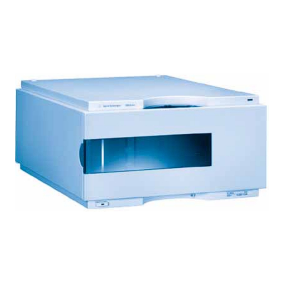
- Page 11 Agilent 1200 Series Quaternary Pump Reference Manual Installing the Pump Site Requirements Unpacking the Quaternary Pump Optimizing the Stack Configuration Installing the Quaternary Pump Flow Connections of the Quaternary Pump Priming and Purging the System Agilent Technologies...
-
Page 12: Installing The Pump
It plugs into the power-input socket at the rear of the quaternary pump. The male end of each of the power cords is different and designed to match the wall socket of a particular country or region. 1200 Series QP Reference Manual... - Page 13 2.5 cm (1.0 inches) of space on either side and approximately 8 cm (3.1 inches) in the rear for the circulation of air and electric connections. If the bench should carry a complete Agilent 1200 Series system, make sure that the bench is designed to carry the weight of all the modules.
- Page 14 C (77–104 Non-condensing Operating Altitude Up to 2000 m (6500 ft) Non-operating altitude Up to 4600 m (14950 ft) For storing the quaternary pump Safety standards: IEC, CSA, UL Installation Category II, Pollution Degree 2 1200 Series QP Reference Manual...
-
Page 15: Unpacking The Quaternary Pump
The delivery checklist is shown in Table 2. To aid in parts identification, please see Chapter 5, “Parts and Materials”. Please report missing or damaged parts to your local Agilent Technologies sales and service office. Table 2 Quaternary Pump Checklist Description Quantity Quaternary pump... - Page 16 Wrench; 1/4 – 5/16 inch 8710-0510 Wrench; 14 mm 8710-1924 ESD wrist strap 9300-1408 Hex key 4mm 8710-2392 Waste tube (reorder number, 5m) 5062-2463 1.2 m Velocity regulator (reorder number) 5062-2486 PTFE Frit 01018-22707 * ESD: Electrostatic Discharge 1200 Series QP Reference Manual...
- Page 17 Installing the Pump Accessory Kit Contents—Vacuum Degasser Table 4 Accessory Kit Contents G1322-68705 Description Part Number Quantity Syringe 5062-8534 Syringe adapter 9301-1337 Waste tube (reorder number, 5m) 5062-2463 1.2 m Connecting tubes labeled A to D G1322-67300 1200 Series QP Reference Manual...
-
Page 18: Optimizing The Stack Configuration
Installing the Pump Optimizing the Stack Configuration If your quaternary pump is part of a complete Agilent 1200 Series system, you can ensure optimum performance by limiting the configuration of the system stack to the following configuration. This configuration optimizes the system flow path, ensuring minimum delay volume. - Page 19 Analog signal to recorder,for AC power PN see page 186 L A N L i n k C o n f i g I n i t M o d Figure 2 Recommended Stack Configuration (Rear View) 1200 Series QP Reference Manual...
- Page 20 ALS Thermostat is added or if your bench is to high, a two stack configuration may be a better setup. Separate the stack between pump and autosampler and place the stack containing the pump on the right side of the stack containing the autosampler. 1200 Series QP Reference Manual...
-
Page 21: Installing The Quaternary Pump
1 Place the quaternary pump on the bench in a horizontal position. 2 Ensure the power switch on the front of the quaternary pump is OFF (switch stands out). Status Lamp Power Switch Serial number Figure 3 Front of Quaternary Pump 1200 Series QP Reference Manual... - Page 22 AUX output allows the user to monitor the vacuum level in the degasser chamber. An Agilent 1200 Series control module can be connected to the CAN bus at any of the modules in the system except for the degasser. The Agilent ChemStation can be connected to the system through one GPIB or LAN (requires the installation of a LAN- board) cable at any of the modules (except for the degasser), preferably at the detector (MUST for the DAD).
- Page 23 The pump was shipped with default configuration settings. To change these settings, N O T E “Setting the 8-bit Configuration Switch” on page 229 1200 Series QP Reference Manual...
-
Page 24: Flow Connections Of The Quaternary Pump
1 Remove the front cover by pressing the snap fasteners on both sides. Figure 5 Removing the Front Cover 1200 Series QP Reference Manual... - Page 25 7 Using a piece of sanding paper connect the waste tubing to the purge valve and place it into your waste system. 8 If the quaternary pump is not part of a Agilent 1200 Series System stack or placed on the bottom of a stack, connect the corrugated waste tube to the waste outlet of the pump leak handling system.
- Page 26 Inlet Outlet Tube clip (1400-1578) Tubings (G1322-67300) Purge valve Waste tubing (5062-2461) Outlet capillary to autosampler (G1312-67305) MCGV Fitting for corrugated waste tubing (5062-2463, reorder pack, 5m) Figure 6 Flow Connections of the Quaternary Pump 1200 Series QP Reference Manual...
-
Page 27: Priming And Purging The System
Before using a new degasser or new tubings for the first time: 1 Prime all tubings with at least 30 ml of iso-propanol no matter whether the channels will be used with organic mobile phase or with water. 1200 Series QP Reference Manual... - Page 28 Solvents containing volatile ingredients will slightly lose these, if left in the degasser without flow for a prolonged period of time. Therefore priming of the vacuum degasser and the pumping system is required before starting an application. 1200 Series QP Reference Manual...
- Page 29 Best solvent to re-dissolve using buffers buffer cristals After a solvent change Bidistilled water Best solvent to re-dissolve buffer cristals After the installation of normal Hexane + 5% Isopropanol Good wetting properties phase seals (P/N 0905-1420) 1200 Series QP Reference Manual...
- Page 30 Installing the Pump 1200 Series QP Reference Manual...
-
Page 31: Optimizing Performance
Agilent 1200 Series Quaternary Pump Reference Manual Optimizing Performance Hints for Successful Use of the Quaternary Pump Solvent Information Prevent Blocking of Solvent Filters Operational Hints for the Vacuum Degasser Operational Hints for the Multi Channel Gradient Valve (MCGV) When to use the Seal Wash Option... -
Page 32: Hints For Successful Use Of The Quaternary Pump
• Always place the solvent cabinet with the solvent bottles on top of the quaternary pump (or at a higher level). • When using salt solutions and organic solvents in the Agilent 1200 Series Quaternary Pump it is recommended to connect the salt solution to one of the bottom gradient valve ports and the organic solvent to one of the upper gradient valve ports. -
Page 33: Solvent Information
• Chromatographic grade ethers, which can contain peroxides (for example, THF, dioxane, di-isopropylether) such ethers should be filtered through dry aluminium oxide which adsorbs the peroxides. • Mixtures of carbon tetrachloride with 2-propanol or THF dissolve stainless steel. 1200 Series QP Reference Manual... -
Page 34: Prevent Blocking Of Solvent Filters
(due to hydrostatic pressure). If the solvent filter is partly blocked no solvent or only very little solvent will drip out of the solvent tube. 1200 Series QP Reference Manual... - Page 35 • Thoroughly flush the filter with bidistilled water (remove all nitric acid, some capillary columns can be damaged by nitric acid). • Replace the filter. Never use the system without solvent filter installed. N O T E 1200 Series QP Reference Manual...
-
Page 36: Operational Hints For The Vacuum Degasser
• quaternary pump was turned off for a length of time (for example, during night) and volatile solvent mixtures are used, or • solvents have been changed. For more information see the Reference Manual for the Agilent 1200 Series vacuum degasser. 1200 Series QP Reference Manual... -
Page 37: Operational Hints For The Multi Channel Gradient Valve (Mcgv)
A -organic solvent) the salt can fall into the port of the organic solvent and may lead to performance problems. When using salt solutions and organic solvents in the Agilent 1200 Series Quaternary N O T E Pump it is recommended to connect the salt solution to one of the bottom ports and the organic solvent to one of the upper gradient valve ports. -
Page 38: When To Use The Seal Wash Option
For information on the installation of the active seal wash option refer to “Installing the Seal Wash Option” on page 114. 1200 Series QP Reference Manual... -
Page 39: When To Use Alternative Seals
Polyethylene seals have a limited pressure range 0–200 bar. When used above 200 bar their N O T E lifetime will be significantly reduced. DO NOT apply the seal wear-in procedure performed with new standard seals at 400 bar. 1200 Series QP Reference Manual... -
Page 40: Optimize The Compressibility Compensation Setting
(for example, 339X integrator) and set parameters. Zero 50% Att 2^3 Chart Speed 10 cm/min 4 Start the recording device with the plot mode. 1200 Series QP Reference Manual... - Page 41 Table 6 Solvent Compressibility Solvent (pure) Compressibility (10 /bar) Acetone Acetonitrile Benzene Carbon tetrachloride Chloroform Cyclohexane Ethanol Ethyl acetate Heptane Hexane Isobutanol Isopropanol Methanol 1-Propanol Toluene Water 1200 Series QP Reference Manual...
- Page 42 Optimizing Performance 1200 Series QP Reference Manual...
- Page 43 Agilent 1200 Series Quaternary Pump Reference Manual Troubleshooting and Test Functions Overview of the Pump’s Indicators and Test Functions Status Indicators Error Messages Pressure Test Leak Test Agilent Technologies...
-
Page 44: Troubleshooting And Test Functions
When a problem with the quaternary pump is suspected, use this test to help troubleshoot the quaternary pump and its pumping performance. The following sections describe these functions in detail (see “Leak Test” on page 87). 1200 Series QP Reference Manual... -
Page 45: Status Indicators
The power supply indicator is integrated into the main power switch. When the indicator is illuminated (green) the power is ON. When the indicator is off, the module is turned OFF. Otherwhise check power connections, availability of power or check functioning of the power supply. 1200 Series QP Reference Manual... -
Page 46: Pump Status Indicator
Call your local service provider for assistance upon observing this error condition. • A flashing red status indicator indicates a severe error during the startup procedure of the module. Call your local service provider for assistance upon observing this error condition. 1200 Series QP Reference Manual... -
Page 47: Error Messages
(for example, repair, frit exchange or exchange of consumables required). In the event of such a failure, the red status indicator at the front of the quaternary pump is switched on, and an entry is written into the instrument logbook. 1200 Series QP Reference Manual... -
Page 48: Timeout
• A not-ready condition was present during a sequence or multiple-injection run for a period longer than the timeout threshold. Suggested Actions Check the logbook for the occurrence and source of a not-ready condition. Restart the analysis where required. 1200 Series QP Reference Manual... -
Page 49: Shut-Down
Fix the leak in the external instrument before restarting the quaternary pump. Check external instruments for a shut-down condition. Check the vacuum degasser for an error condition. Refer to the Reference Manual for the Agilent 1200 Series vacuum degasser. 1200 Series QP Reference Manual... -
Page 50: Remote Timeout
• Defective components in the instrument showing the not-ready condition. Suggested Actions Ensure the instrument showing the not-ready condition is installed correctly, and is set up correctly for analysis. Exchange the remote cable. Check the instrument for defects (refer to the instrument’s reference documentation). 1200 Series QP Reference Manual... -
Page 51: Synchronization Lost
Suggested Actions Ensure all the CAN cables are connected correctly. Switch off the system. Restart the system, and determine which module or modules are not recognized by the system. Ensure all CAN cables are installed correctly. 1200 Series QP Reference Manual... -
Page 52: Leak
Ensure all fittings are tight. Exchange defective capillaries. Ensure pump components are seated correctly. If there are still signs of a leak, exchange the appropriate seal (purge valve, active inlet valve, outlet ball valve). Exchange the pump seals. 1200 Series QP Reference Manual... -
Page 53: Leak Sensor Open
• Leak sensor not connected to the LPM board. • Defective leak sensor. • Leak sensor incorrectly routed, being pinched by a metal component. Suggested Actions Ensure the leak sensor is connected correctly. Exchange the leak sensor. 1200 Series QP Reference Manual... -
Page 54: Leak Sensor Short
If the current increases above the upper limit, the error message is generated. Probable Causes • Defective leak sensor. • Leak sensor incorrectly routed, being pinched by a metal component. Suggested Actions Exchange the leak sensor. 1200 Series QP Reference Manual... -
Page 55: Compensation Sensor Open
If the resistance across the sensor increases above the upper limit, the error message is generated. Probable Causes • Defective LPM board. Suggested Actions Exchange the LPM board. 1200 Series QP Reference Manual... -
Page 56: Compensation Sensor Short
If the resistance across the sensor falls below the lower limit, the error message is generated. Probable Causes • Defective LPM board. Suggested Actions Exchange the LPM board. 1200 Series QP Reference Manual... -
Page 57: Fan Failed
• Defective fan. • Defective LPM board. • Improperly positioned cables or wires obstructing fan blades. Suggested Actions Ensure the fan is connected correctly. Exchange fan. Exchange the LPM board. Ensure the fan is not mechanically blocked. 1200 Series QP Reference Manual... -
Page 58: Open Cover
• Sensor defective. • Rear of the module is exposed to strong direct sunlight. Suggested Actions Replace the top foam. Exchange the LPM board. Ensure that the rear of module is not directly exposed to strong sunlight. 1200 Series QP Reference Manual... -
Page 59: Restart Without Cover
• The quaternary pump started with the top cover and foam removed. • Rear of the module is exposed to strong direct sunlight. Suggested Actions Replace the top cover and foam. Ensure that the rear of module is not directly exposed to strong sunlight. 1200 Series QP Reference Manual... -
Page 60: Zero Solvent Counter
Probable Causes • Volume in bottle below specified volume. • Incorrect setting of limit. Suggested Actions Refill bottles and reset solvent counters. 1200 Series QP Reference Manual... -
Page 61: Pressure Above Upper Limit
• purge-valve frit. • needle (autosampler), • seat capillary (autosampler), • sample loop (autosampler), and • column frits. • capillaries with low internal diameters (e.g. 0.12mm id). Exchange the damper. Exchange the LPM board. 1200 Series QP Reference Manual... -
Page 62: Pressure Below Lower Limit
Inspect the pump head, capillaries and fittings for signs of a leak. Purge the quaternary pump. Run a pressure test to determine whether the seals or other pump components are defective. Exchange the damper. Exchange the LPM board. 1200 Series QP Reference Manual... -
Page 63: Pressure Signal Missing
If the pressure signal is missing, the processor detects a voltage of approximately -120mV across the damper connector. Probable Causes • Damper disconnected. • Defective damper. Suggested Actions Ensure the damper is connected correctly to the LPM board. Exchange the damper. 1200 Series QP Reference Manual... -
Page 64: Missing Pressure Reading
10 seconds, the error message is generated. Probable Causes • Damper not connected. • Defective damper. • Defective LPM board. Suggested Actions Ensure the damper is connected, clean and seated correctly. Exchange the damper. Exchange the LPM board. 1200 Series QP Reference Manual... -
Page 65: Pump Configuration
However, the pump will function as an isocratic pump in this configuration.The error message reappears after each switch-on. Probable Causes • Gradient valve disconnected. Suggested Actions Reconnect the gradient valve. 1200 Series QP Reference Manual... -
Page 66: Valve Fuse
• Defective connection cable (front panel to LPM board). • Defective LPM board. Suggested Actions Restart the quaternary pump. If the error message appears again, exchange the gradient valve. Exchange the connection cable. Exchange the LPM board. 1200 Series QP Reference Manual... -
Page 67: Inlet-Valve Fuse
• Defective connection cable (front panel to LPM board). • Defective LPM board. Suggested Actions Restart the quaternary pump. If the error message appears again, exchange the active inlet valve. Exchange the connection cable. Exchange the LPM board. 1200 Series QP Reference Manual... -
Page 68: Valve Failed
• Connection cable (inside instrument) not connected. • Connection cable (inside instrument) defective. • Gradient valve defective. Suggested Actions Ensure the gradient valve is connected correctly. Ensure the connection cable is connected correctly. Exchange the connection cable. Exchange the gradient valve. 1200 Series QP Reference Manual... -
Page 69: Motor-Drive Power
Exchange the active inlet valve. Exchange the outlet ball valve. Remove the pump-head assembly. Ensure there is no mechanical blockage of the pump-head assembly or pump drive assembly. Exchange the pump drive assembly. Exchange the LPM board. 1200 Series QP Reference Manual... -
Page 70: Encoder Missing
2 seconds. If the connector is not detected by the processor, the error message is generated. Probable Causes • Defective or disconnected pump encoder connector. • Defective pump drive assembly. Suggested Actions Ensure the connector is clean, and seated correctly. Exchange the pump drive assembly. 1200 Series QP Reference Manual... -
Page 71: Inlet-Valve Missing
Ensure the pins of the active inlet valve connector are not damaged. Ensure the connector is seated securely. Ensure the connection cable is seated correctly. Exchange the cable if defective. Exchange the active inlet valve. 1200 Series QP Reference Manual... -
Page 72: Temperature Out Of Range
The values supplied to the ADC by the hybrid sensors must be between 0.5 V and 4.3 V. If the values are outside this range, the error message is generated. Probable Causes • Defective LPM board. Suggested Actions Exchange the LPM board. 1200 Series QP Reference Manual... -
Page 73: Temperature Limit Exceeded
Ensure the outlet valve is not blocked. Remove the pump head assembly. Ensure there is no mechanical blockage of the pump head assembly or pump drive assembly. Exchange the pump drive assembly. Exchange the LPM board. 1200 Series QP Reference Manual... -
Page 74: Servo Restart Failed
LPM board. Exchange the active inlet valve. Remove the pump-head assembly. Ensure there is no mechanical blockage of the pump-head assembly or pump drive assembly. Exchange the pump drive assembly. Exchange the LPM board. 1200 Series QP Reference Manual... -
Page 75: Pump Head Missing
• Pump head not installed correctly (screws not secured, or pump head not seated correctly). • Broken plunger. Suggested Actions Install the pump head correctly. Ensure nothing (e.g. capillary) is trapped between the pump head and body. Exchange the plunger. 1200 Series QP Reference Manual... -
Page 76: Index Limit
• Defective pump drive assembly. Suggested Actions Remove the pump head, and examine the seals, plungers, and internal components for signs of wear, contamination or damage. Exchange components as required. Exchange the pump drive assembly. 1200 Series QP Reference Manual... -
Page 77: Index Adjustment
• Defective pump drive assembly. Suggested Actions Remove the pump head, and examine the seals, plungers, and internal components for signs of wear, contamination or damage. Exchange components as required. Exchange the pump drive assembly. 1200 Series QP Reference Manual... -
Page 78: Index Missing
• Disconnected or defective encoder cable. • Defective pump drive assembly. Suggested Actions Ensure the encoder cable are not damaged or dirty. Make sure the cables are connected securely to the LPM board. Exchange the pump drive assembly. 1200 Series QP Reference Manual... -
Page 79: Stroke Length
This current increase causes the error message to be generated. Probable Causes • Defective pump drive assembly. Suggested Actions Exchange the pump drive assembly. 1200 Series QP Reference Manual... -
Page 80: Initialization Failed
Probable Causes • Blocked active inlet valve. • Defective pump drive assembly. • Defective LPM board. Suggested Actions Exchange the active inlet valve. Exchange the pump drive assembly. Exchange the LPM board. 1200 Series QP Reference Manual... -
Page 81: Wait Timeout
Ensure pump components are seated correctly. If there are still signs of a leak, exchange the appropriate seal (purge valve, active inlet valve, outlet ball valve, plunger seal). Ensure correct operating condition for the special application in use. Exchange the defective pump drive assembly. 1200 Series QP Reference Manual... -
Page 82: Pressure Test
(IPA), while monitoring the pressure profile (using an integrator on the analog output, or in the plot screen in the ChemStation). The pressure profile is shown in Figure Pressure [bar] Step 2 Step 1 Time [minutes] Figure 8 Typical Pressure-Test Pressure Profile with IPA 1200 Series QP Reference Manual... -
Page 83: Running The Pressure Test
N O T E thoroughly flushed with IPA before starting to pressurize the system! Any trace of other solvents or the smallest air bubble inside the flow path definitely will cause the test to fail! 1200 Series QP Reference Manual... - Page 84 The handheld controller displays a graphical representation of the pressure. “Evaluating the Results” on page 85 describes the evaluation and interpretation of the pressure test results. 9 When the test is finished slowly open the purge valve to release the pressure in the system. 1200 Series QP Reference Manual...
-
Page 85: Evaluating The Results
(eg. autosampler, port 6 of the injection valve), and repeat the pressure test. Exclude each module one by one to determine which module is leaking. • If the pump is determined to be the source of the leak, run the leak test. 1200 Series QP Reference Manual... -
Page 86: Potential Causes Of Pressure Test Failure
Exchange the plunger if required. Needle seat. Exchange the needle seat. Potential Cause (Column Compartment) Corrective Action Loose or leaky fitting. Tighten or exchange the fitting or capillary. Rotor seal (column switching valve). Exchange the rotor seal. 1200 Series QP Reference Manual... -
Page 87: Leak Test
Control Module G1323B or the ChemStation). Plateau 3 Pressure [bar] Ramp 4 Plateau 2 Ramp 3 Plateau 1 Ramp 2 Ramp 1 Time [minutes] Figure 9 Typical Leak-Test Pressure Profile with IPA 1200 Series QP Reference Manual... - Page 88 When the system pressure reaches 390 bar, the flow is reduced to zero, and the pressure stabilizes just below 400 bar. Plateau 3: 1 min after reaching the maximum pressure, the pressure drop should not exceed 2 bar/min. 1200 Series QP Reference Manual...
-
Page 89: Running The Leak Test
3 Set flow to 5 ml/min for channel D and flush the degasser channel for about 10minutes. 4 Turn off pump operation and close the purge valve. 5 Connect the restriction capillary (G1313-87305) to pump outlet. 1200 Series QP Reference Manual... - Page 90 “Evaluating the Results” on page 85 describes the evaluation and interpretation of the leak test results. 12 When the test is finished slowly open the purge valve to release the pressure in the system. 1200 Series QP Reference Manual...
-
Page 91: Evaluating The Results
No Pressure increase at Ramp 1 Potential Cause Corrective Action Pump not running. Check the logbook for error messages. Purge valve open. Close the purge valve, and restart the test. 1200 Series QP Reference Manual... - Page 92 Ensure the pump head screws are tight. Leaking seals or scratched plungers. Exchange the pump seals. Check the plungers for scratches. Exchange if scratched. Leaking outlet valve. Exchange the outlet valve. Leaky damper. Exchange damper. 1200 Series QP Reference Manual...
- Page 93 Large leaks (visible) at the pump seals. Exchange the pump seals. Large leaks (visible) at active inlet valve, outlet Ensure the leaky components are installed valve, or purge valve. tightly. Exchange the component if required. 1200 Series QP Reference Manual...
- Page 94 Ensure the pump head screws are tight. Leaking seals or scratched plungers. Exchange the pump seals. Check the plungers for scratches. Exchange if scratched. Leaking outlet valve. Exchange the outlet valve. Leaky damper. Exchange damper. 1200 Series QP Reference Manual...
- Page 95 Agilent 1200 Series Quaternary Pump Reference Manual Repairing the Pump Introduction to Repairing the Pump Overview of Repairing the Pump Simple Repair Procedures Agilent Technologies...
-
Page 96: Repairing The Pump
Electronic boards and components are sensitive to electrostatic discharge (ESD). In C A U T I O N order to prevent damage always use an ESD protection (for example, the ESD wrist strap from the accessory kit) when handling electronic boards and components. 1200 Series QP Reference Manual... - Page 97 2 Unroll the rest of the band and peel the liner from the copper foil at the opposite end. 3 Attach the copper foil to a convenient and exposed electrical ground. Figure 11 Using the ESD Strap 1200 Series QP Reference Manual...
-
Page 98: Overview Of Repairing The Pump
121 Outlet ball valve, page 104 Fan, Purge valve, page 142 page 106 Damping unit, Active inlet valve, page 139 page 100 MCGV, page 122 Leak sensor, page 153 Figure 12 Overview of Repair Procedures 1200 Series QP Reference Manual... -
Page 99: Simple Repair Procedures
Seal life time shorter than normally expected — check plungers while changing the seals “Installing the Seal Wash Option” If seals show indication of Leaks at lower pump head side, loss of wash page 114 leaks solvent 1200 Series QP Reference Manual... -
Page 100: Exchanging The Active Inlet Valve
4 Unscrew the adapter from the active inlet valve. 5 Using a 14 mm wrench loosen the active inlet valve and remove the valve from pump head. Valve body Valve cartridge Figure 13 Active Inlet Valve Assembly 1200 Series QP Reference Manual... - Page 101 After an exchange of the valve it may take several ml of pumping with the solvent used in N O T E the current application, before the flow stabilizes at a %-ripple as low as it used to be when the system was still working properly. 1200 Series QP Reference Manual...
-
Page 102: Exchanging The Active Inlet Valve Cartridge
12 Reconnect the adapter at the active inlet valve. 13 Reconnect the solvent inlet tube to the adapter. Reconnect the active inlet valve cable to the connector in the Z-panel. 14 Reinstall the front cover. 1200 Series QP Reference Manual... - Page 103 %-ripple as low as it used to be when the system was still working properly. Capillary, pump to injection device Connector Solvent inlet tube Acitve inlet valve cable Adapter Active inlet valve Figure 14 Exchanging the Active Inlet Valve 1200 Series QP Reference Manual...
-
Page 104: Exchanging The Outlet Ball Valve
3 Check that the new valve is assembled correctly and that the gold seal is present (if the gold seal is deformed, it should be replaced). Valve body Gold seal Plastic cap Figure 15 Outlet Ball Valve Parts 4 Reinstall the outlet ball valve and tighten the valve. 1200 Series QP Reference Manual... - Page 105 Repairing the Pump 5 Reconnect the valve capillary. Valve capillary Outlet ball valve Figure 16 Exchanging the Outlet Ball Valve 1200 Series QP Reference Manual...
-
Page 106: Exchanging The Purge Valve Frit Or The Purge Valve
4 Remove the plastic cap with the gold seal from the purge valve. 5 Using a pair of tweezers or a toothpick remove the frit. Valve body PTFE frit Gold seal Plastic cap Figure 17 Purge Valve Parts 1200 Series QP Reference Manual... - Page 107 8 Insert the purge valve into the pump head and locate the pump outlet capillary and the waste tube as shown in Figure 9 Tighten the purge valve and reconnect outlet capillary and waste tubing. Outlet capillary Purge valve Waste tube Figure 18 Exchanging the Purge Valve 1200 Series QP Reference Manual...
-
Page 108: Removing The Pump Head Assembly
5 Remove the waste tubing and disconnect the Active Inlet Valve tubing. 6 Remove the capillary at the bottom of the Pumphead. 7 Using a 4 mm hexagonal key, stepwise loosen the two Pumphead screws and remove the Pumphead from the Pump Drive. 1200 Series QP Reference Manual... -
Page 109: Exchanging The Pump Seals And Seal Wear-In Procedure
(two revolutions) and while holding the lower half lift the housing away from the plungers. of the assembly carefully pull the pump head away from the plunger housing. Support ring Pump head Lock screw Plunger housing Plunger Plunger housing 1200 Series QP Reference Manual... - Page 110 4 Insert new seals into the pump head. the pump head (be careful not to break the plunger). Remove wear retainers, if still present. Seals Seal 5 Reassemble the Pumphead assembly. Pump head Support ring Plunger housing 1200 Series QP Reference Manual...
-
Page 111: Seal Wear-In Procedure
6 Turn OFF the pump, slowly open the purge valve to release the pressure from the system, disconnect the restriction capillary and reinstall the bottle with the solvent for your application. 7 Rinse your system with the solvent used for your next application. 1200 Series QP Reference Manual... -
Page 112: Exchanging The Plungers
1 Disassemble the Pumphead assembly. 2 Check the plunger surface and remove any deposits or layers. Cleaning can be done with alcohol or tooth paste. Replace plunger if scratched. Support ring Plunger surface Plunger housing Plunger 1200 Series QP Reference Manual... - Page 113 Repairing the Pump 3 Reassemble the Pumphead assembly. Pump head Support ring Plunger housing 1200 Series QP Reference Manual...
-
Page 114: Installing The Seal Wash Option
Switch off the pump at the main power switch procedure Remove the front cover Remove the top cover and foam 1 By using a screwdriver remove the metal plug in the z-panel. Figure 19 Removing the metal plug from the z-panel 1200 Series QP Reference Manual... -
Page 115: Repairing The Pump
8 Place the pump head, on the backside of the plungerhousing, on a flat surface. Loosen the lock screw (two revolutions) and while holding the 1200 Series QP Reference Manual... - Page 116 12 Insert the plungers and carefully press them into the seal. 13 Tighten the lock screw. 14 Slide the pump head assembly onto the metering drive. Apply a small amount of pump head grease (part number 79846-65501) to the pumphead 1200 Series QP Reference Manual...
- Page 117 16 Route the wash inlet tube into a bottle filled with a mixture of distilled water and isopropanol (90/10) and place the bottle above the pump in the solvent cabinet. 17 Route the outlet of the wash tube into a waste container. Figure 22 Pumphead after completed installation. 1200 Series QP Reference Manual...
-
Page 118: Exchanging The Wash Seals
1 Disconnect all capillaries and tubes from the pump head 2 Using a 4-mm hexagonal key stepwise and disconnect the active inlet valve cable. loosen and remove the two pump head screws and remove the pump head from the pump drive. Pump head screws 1200 Series QP Reference Manual... - Page 119 Place a seal wash gasket in the recess of the support ring. housing together. Insert tool Pump head Seal Support ring Support ring Plunger housing 1200 Series QP Reference Manual...
- Page 120 Apply a small amount of pump head grease to the cable to its connector. pumphead screws and the balls of the spindle drive. Tighten the pumphead screws stepwise with increasing torque. Metering drive Balls of spindle drive Pump head Pumphead screws 1200 Series QP Reference Manual...
-
Page 121: Reinstalling The Pump Head Assembly
3 Using a 4 mm hexagonal key tighten the Pumphead screws stepwise with increasing torque. Pump head screws 4 Reconnect the capillaries, tubing and the Active Inlet Valve cable to the connector. 5 Reinstall the front cover. 1200 Series QP Reference Manual... -
Page 122: Exchanging The Multi-Channel Gradient Valve (Mcgv)
Such leaks will interfere with the general performance of the valve When using buffer solutions and organic solvents in the Agilent 1200 Series Quaternary Pump it is recommended to connect the buffer solution to one of the bottom ports and the organic solvent to one of the upper gradient valve ports. - Page 123 MCGV, unclip them from the tube cover. clips and place them into the solvent cabinet to avoid flow by hydrostatic pressure. MCGV Solvent Waste tubes funnel Cover Waste tube Cover Connecting tube MCGV to AIV 1200 Series QP Reference Manual...
- Page 124 A to D of the MCGV. Make sure the orientation of MCGV cover. the channels on the cover is labelled as shown below, otherwhise re-label the cover. Waste MCGV funnel Solvent Waste tubes funnel Wast Cover e tube Cover Connecting tube MCGV to AIV 1200 Series QP Reference Manual...
-
Page 125: Exchanging The Optional Interface Board
3 Loosen the screws. Slide out the interface board from the quaternary pump. 4 Install the new interface board. Secure screws. 5 Reconnect the cables to the board connector. 6 Reconnect the pump to line power. BCD (Interface) board Figure 23 Exchanging the Interface Board 1200 Series QP Reference Manual... -
Page 126: Exchanging Internal Parts
C A U T I O N ESD kit when handling internal parts. The procedures in this section describe how to exchange internal parts. You must remove the quaternary pump from the stack in order to open the main cover. 1200 Series QP Reference Manual... -
Page 127: Removing The Top Cover And Foam
1 Remove the front cover by pressing the both clip fasteners 2 Unplug the power cord and move the lever towards the on both sides of the cover. power socket. Lever Clip fastener (1) 1200 Series QP Reference Manual... - Page 128 Screws Cover Cover clip clip 5 If an optional interface board is installed, remove it from 6 Remove the top foam. the pump slot. Safety light switch 1200 Series QP Reference Manual...
- Page 129 A safety light switch on the main board will prevent operation when the covers are removed. Top foam cover The next figure shows the position of the safety light switch on the board. Light light switch Foam lever 1200 Series QP Reference Manual...
-
Page 130: Exchanging The Low Pressure Pump Main Board (Lpm Board)
2 Remove the top cover and foam (see “Removing the Top Cover and Foam” on page 127). 3 Disconnect all connectors from the main board. When removing connectors, counterhold on connector J3 with one hand. N O T E 1200 Series QP Reference Manual... - Page 131 Figure 24 LPM Board Connectors Table 8 Identifying Connectors on the LPM Board Connector Description Connector Description RS232 Encoder Remote Analog Pressure signal Leak sensor GPIB Damper J5/6 CAN connector Power supply Interface board Motor MCGV 1200 Series QP Reference Manual...
- Page 132 (the RFI spring plate is NOT part of an exchange board). If you have to exchange other parts also, continue with that work, first. N O T E 1200 Series QP Reference Manual...
- Page 133 You must change the type of the replacement main board to agree with the quaternary pump (G1311A). The type can be entered using either the Control Module G1323B, or the Instant Pilot G4208A, or the ChemStation. 1200 Series QP Reference Manual...
- Page 134 If you are using the Instant Pilot G4208A you will enter the product number of the quaternary pump (G1310A) without the TYPE command. To learn how to set the product number, please refer to section “Entering the ProductNumber/Serial Number Using the Instant Pilot G4208A” on page 136. 1200 Series QP Reference Manual...
- Page 135 5 Letters and numbers are created using the up and down arrows. Into the box labeled Serial#, enter the 10-character serial number for the quaternary pump. When the 10-character serial number is entered, press Enter to highlight the complete serial number. Then, press Done (F6). 1200 Series QP Reference Manual...
- Page 136 7 Turn the pump OFF then ON again. The Maintenance screen should display the correct serial number for this module. 8 If an Agilent ChemStation is also connected, restart the Agilent ChemStation now as well. 1200 Series QP Reference Manual...
- Page 137 The reply line will respond with RA 0000 SER followed by the module serial number you just entered. 2 Turn off the quaternary pump, then on again. Then, re-boot the ChemStation. If the serial number you have just entered is different than 1200 Series QP Reference Manual...
- Page 138 Technical Support - Life Sciences & Chemical Analysis Solutions - Software Downloads & Utilities http://www.chem.agilent.com section Technical Support to download and install always the newest available version of firmware on your system or call your local service provider for assistance. 1200 Series QP Reference Manual...
-
Page 139: Exchanging The Damper
“Exchanging the Multi-Channel Gradient Valve Remove the front cover, top cover and top foam section (MCGV)” on page 122). (see “Removing the Top Cover and Foam” on page 127). Cover 1200 Series QP Reference Manual... - Page 140 5 Disconnect the damper connector at the main board (J24). 6 Place the new damper into the recess and connect to the Lift the damper out of its position. main board (J24). Damper Damper Connector Connector Damper Damper 1200 Series QP Reference Manual...
- Page 141 10 Replace the top foam section, optional interface board (if tubings back to the valve installed), metal cover and top cover (see “Replacing the ports. Top Cover and Foam” on page 157). Replace the pump on stack, reconnect all tubings and cables. 1200 Series QP Reference Manual...
-
Page 142: Exchanging The Fan
Make sure that air flow is directed as indicated (same direction for arrow on the fan C A U T I O N and arrow on the bottom foam). 6 Reinstall foam, top covers and front cover, see “Replacing the Top Cover and Foam” on page 157. 1200 Series QP Reference Manual... - Page 143 Repairing the Pump 7 Replace the pump on stack, reconnect all tubings and cables. J25, fan Air flow Figure 26 Exchanging the Fan 1200 Series QP Reference Manual...
-
Page 144: Exchanging The Pump Drive
2 Disconnect all capillaries and tubes from the pump head valve (MCGV) and remove the valve and disconnect the active inlet valve connector. cover (see “Exchanging the Multi-Channel Gradient Valve (MCGV)” on page 122). Cover 1200 Series QP Reference Manual... - Page 145 5 Loosen the screws of the Z-panel and take it out of the 6 Using a 4-mm hexagonal key stepwise instrument. loosen and remove the two pump head screws and remove the pump head from the pump drive. Screws Pump head screws Z-panel 1200 Series QP Reference Manual...
- Page 146 (J16 Motor, J17 Encoder). 9 Reinstall the pump head and fix with the two screws. 10 Replace the Z-panel and fix it with the two screws. Screws Z-panel Pump head screws 1200 Series QP Reference Manual...
- Page 147 11 Replace the MCGV cover and connect the connection tube 12 Replace the pump on stack, reconnect all tubings and to the middle position of the MCGV (see “Exchanging the cables. Multi-Channel Gradient Valve (MCGV)” on page 122). Cover 1200 Series QP Reference Manual...
-
Page 148: Exchanging The Power Supply
127 1 Disconnect all capillaries, tubes and connectors from the 2 Loosen the two Z-panel screws and remove pump head and the damper. Remove the MCDV cover. Screws Pump head Damper MCGV Z-panel 1200 Series QP Reference Manual... - Page 149 5 Push the leak sensor cable through the recess in the foam 6 Loosen and remove the power supply screws at the rear and lift the bottom foam out of the instrument. panel. Power supply screws 1200 Series QP Reference Manual...
- Page 150 9 Place the new power supply into the instrument and fix 10 Install the coupler onto the power supply switch and clip the two screws at the back plane. the light pipe back onto the coupler. Coupler Light pipe 1200 Series QP Reference Manual...
- Page 151 Pressure Pump Main Board (LPM Board)” on page 130. 13 Re-install pump assembly, fan and damper into the bottom 14 Place the Z-panel into its position and tighten the two foam and re-connect to the main board. screws. Screws Z-panel 1200 Series QP Reference Manual...
- Page 152 16 Install foam and top cover, see “Replacing the Top Cover capillaries, tubes and cables to the pump head, the MCGV and Foam” on page 157. Replace the pump on stack, and the damper. reconnect all tubings and cables. 1200 Series QP Reference Manual...
-
Page 153: Exchanging The Leak Sensor
11 Install the pump assembly, the fan, the damper and the Z-panel, see “Exchanging the Power Supply” on page 148. Reconnect all cables and capillaries. 12 Replace top foam and top cover, see “Replacing the Top Cover and Foam” page 157. 1200 Series QP Reference Manual... - Page 154 Repairing the Pump 13 Replace the pump on stack, reconnect all tubings and cables. To main board J23 Leak sensor Leak pan Figure 27 Exchanging the Leak Sensor 1200 Series QP Reference Manual...
-
Page 155: Exchanging The Status Light Pipe
“Removing the Top Cover and procedure Foam” on page 127 1 The status light pipe is clipped into the top cover. 2 Replace the top cover, see “Replacing the Top Cover and Foam” on page 157. 1200 Series QP Reference Manual... -
Page 156: Assembling The Main Cover
1 Place the top part on the bench and insert the left and right 2 Replace the cover. side into the top part. Front 3 Replace the quaternary pump into the stack and reconnect the cables and capillaries. 4 Turn on the quaternary pump. 1200 Series QP Reference Manual... -
Page 157: Replacing The Top Cover And Foam
Make sure that after your repair all assemblies, cables, capillaries and procedure connectors are located in its correct place. 1 Replace the top foam section. 2 Make sure that the foam is installed correctly and is located in the safety light switch. Light switch 1200 Series QP Reference Manual... - Page 158 6 Replace the top cover. Replace the pump on stack, underneath the Z-Panel in the front, then lower the back of reconnect all tubings and cables. the metal plate (2)) and fix the two holding screws. Holding screws 1200 Series QP Reference Manual...
- Page 159 Leak funnel Waste tube holder 1200 Series QP Reference Manual...
- Page 160 Repairing the Pump 1200 Series QP Reference Manual...
-
Page 161: Parts And Materials
Agilent 1200 Series Quaternary Pump Reference Manual Parts and Materials Overview of Main Assemblies Solvent Cabinet Bottle Head Assembly Hydraulic Path Cover Parts Sheet Metal Kit Foam Parts Power and Status Light Pipes Leak Parts Pump Head Assembly Pump Head Assembly with Seal Wash Option... -
Page 162: Overview Of Main Assemblies
Parts and Materials Overview of Main Assemblies Figure 28 Overview of Main Assemblies (Front View) 1200 Series QP Reference Manual... - Page 163 Fan assembly 3160-1016 Damping unit 79835-60005 Leak pan — pump 5042-8590 Multi-gradient assembly (MCGV) G1311-67701 Exchange assembly — MCGV G1311-69701 Screw, M4, 40 mm lg — MCGV 0515-0906 Rubber holder — MCGV 1520-0401 MCGV cover G1311-44101 1200 Series QP Reference Manual...
- Page 164 Washer — analog output 2190-0699 Standoff — remote connector 1251-7788 Standoff — GPIB connector 0380-0643 Power supply (behind rear panel) 0950-2528 Screw, M4, 7 mm lg — power supply 0515-0910 Washer — power supply 2190-0409 1200 Series QP Reference Manual...
-
Page 165: Solvent Cabinet
Solvent cabinet, including all plastic parts 5065-9981 Name plate, Agilent 1200 5042-8901 Front panel, solvent cabinet 5065-9981 Leak pan, solvent cabinet 5042-8567 Bottle transparent 9301-1420 Bottle amber 9301-1450 Bottle-head assembly, see page 166 G1311-60003 Figure 30 Solvent Cabinet Parts 1200 Series QP Reference Manual... -
Page 166: Bottle Head Assembly
Ferrules with lock ring 5063-6598 (10x) Tube screw 5063-6599 (10x) Wire marker No part number Solvent tubing, 5 m 5062-2483 Frit adapter (pack of 4) 5062-8517 Solvent inlet filter, 20µm 5041-2168 Figure 31 Bottle-Head Assembly Parts 1200 Series QP Reference Manual... -
Page 167: Hydraulic Path
Solvent tube, vacuum degasser to MCGV (pack of 4) G1322-67300 Capillary, plunger 1 to damper G1311-67301 Capillary, damper to plunger 2 G1311-67300 Connecting tube, MCGV to AIV G1311-67304 Waste tube, reoder pack, 5 m 5062-2461 1200 Series QP Reference Manual... - Page 168 Parts and Materials Figure 32 Hydraulic Flow Path of the Quaternary Pump 1200 Series QP Reference Manual...
-
Page 169: Cover Parts
Cover Parts Table 14 Cover Parts Item Description Part Number Cover kit (includes top, both sides, base) 5065-9985 Front plate G1311-68714 Logo plate, Agilent 1200 5042-8901 1 (top) 1 (base) 1 (side) Figure 33 Cover Parts 1200 Series QP Reference Manual... -
Page 170: Sheet Metal Kit
Sheet Metal Kit Table 15 Sheet Metal Kit Item Description Part Number Sheet metal kit, includes top, base and Z-panel G1311-68701 Screw, for cover and Z-Panel 5022-2112 Board cover 5001-3772 Z-panel Figure 34 Sheet Metal Kit 1200 Series QP Reference Manual... -
Page 171: Foam Parts
Foam Parts Table 16 Foam Parts Item Description Part Number Foam Kit (includes upper and lower foam) G1311-68702 Bushing, for pump drive 1520-0404 Board Guides 5041-8395 1 (upper foam) 1 (lower foam) Figure 35 Foam Parts 1200 Series QP Reference Manual... -
Page 172: Power And Status Light Pipes
Power and Status Light Pipes Item Description Part Number Power switch coupler 5041-8383 Light pipe — power switch 5041-8382 Power switch button 5041-8381 Light pipe — status lamp 5041-8384 Figure 36 Power and Status Light Pipes 1200 Series QP Reference Manual... -
Page 173: Leak Parts
Table 18 Leak Parts Item Description Part Number Leak sensor 5061-3356 Tube clip 5041-8387 Leak pan, pump 5042-8590 Leak funnel 5041-8388 Holder, leak funnel 5041-8389 Corrugated waste tube (reorder pack), 5m 5062-2463 Figure 37 Leak Parts 1200 Series QP Reference Manual... -
Page 174: Pump Head Assembly
Pump chamber housing G1311-25200 Active inlet valve body G1312-60025 Replacement cartridge for active inlet valve (400 bar) 5062-8562 Outlet ball valve G1311-60012 Screw lock 5042-1303 Purge valve assembly G1311-60009 Screw M5, 60 mm lg 0515-2118 1200 Series QP Reference Manual... - Page 175 Parts and Materials Figure 38 Pump Head Assembly 1200 Series QP Reference Manual...
-
Page 176: Pump Head Assembly With Seal Wash Option
Replacement cartridge for active inlet valve (400 bar) 5062-8562 Outlet ball valve (complete with cartridge) G1311-60012 Screw lock 5042-1303 Purge valve G1311-60009 Screw M5, 60 mm lg 0515-2118 Seal wash pump assembly 5065-9953 Seal wash upgrade kit (see page 182) 01018-68722 1200 Series QP Reference Manual... - Page 177 Parts and Materials Figure 39 Pump Head with Seal Wash Option 1200 Series QP Reference Manual...
-
Page 178: Outlet Ball Valve Assembly
Outlet Ball Valve Assembly Item Description Part Number Outlet ball valve — complete assembly G1311-60012 Socket cap 5042-1345 Outlet valve housing screw 01018-22410 Gold seal, outlet 5001-3707 Cap (pack of 4) 5062-2485 Figure 40 Outlet Ball Valve Assembly 1200 Series QP Reference Manual... -
Page 179: Purge Valve Assembly
Purge-Valve Assembly Item Description Part Number Purge valve — complete assembly G1311-60009 Valve body No part number PTFE frit (pack of 5) 01018-22707 Gold seal 5001-3707 Cap (pack of 4) 5062-2485 Figure 41 Purge-Valve Assembly 1200 Series QP Reference Manual... -
Page 180: Active Inlet Valve Assembly
Table 23 Active Inlet Valve Assembly Item Description Part Number Active inlet valve body — No cartridge included G1312-60025 Valve cartridge (400 bar) 5062-8562 Active inlet valve body Valve cartridge Figure 42 Active Inlet Valve Assembly 1200 Series QP Reference Manual... -
Page 181: Accessory Kit G1311-68705
Corrugated waste tube (reorder number), 5m 5062-2463 Velocity regulator (reorder number, 3) 5062-2486 ESD wrist strap 9300-1408 Hex key 4mm 8710-2392 Wrench 1/4 – 5/16 inch 8710-0510 Capillary, pump to injection device, 600 mm lg, ID 0.17 mm G1329-87300 1200 Series QP Reference Manual... -
Page 182: Seal Wash Option Kit G1311-68711
Secondary seal (pre-installed in support rings) 0905-1175 Gasket, wash seal (2 EA) (for re-order pack of 6) 5062-2484 Seal keeper (2 EA) 5001-3743 Silicone rubber tubing 1mm I.D. (3m) 0890-1764 Seal (pack of 2) 5063-6589 Seals insert tool 01018-2370 1200 Series QP Reference Manual... - Page 183 Agilent 1200 Series Quaternary Pump Reference Manual Identifying Cables Cable Overview Analog Cables Remote Cables BCD Cables Auxiliary Cable CAN Cable External Contact Cable RS-232 Cable Kit LAN Cables This chapter provides information on cables. Agilent Technologies...
-
Page 184: Identifying Cables
Identifying Cables Cable Overview Never use cables other than the ones supplied by Agilent Technologies to ensure WA R N I N G proper functionality and compliance with safety or EMC regulations. Table 26 Cables Overview Type Description Part Number... - Page 185 5181-1516 cables Agilent 1200 module to module, 1 m 5181-1519 Agilent 1200 module to control module G1323-81600 External Agilent 1200 Series interface board to general purpose G1103-61611 contacts GPIB Agilent 1200 module to Agilent ChemStation, 1 m 10833A cable Agilent 1200 module to Agilent ChemStation, 2 m...
-
Page 186: Analog Cables
Identifying Cables Analog Cables One end of these cables provides a BNC connector to be connected to Agilent 1200 Series modules. The other end depends on the instrument to which connection is being made. Agilent 1200 to 3390/2/3 Integrators Connector... - Page 187 Agilent 1200 to 3394/6 Integrators Connector Signal Name 35900-60750 3394/6 Agilent 1200 Not connected Shield Analog - Center Analog + Agilent 1200 to BNC Connector Connector Signal Name 8120-1840 Agilent 1200 Shield Shield Analog - Center Center Analog + 1200 Series QP Reference Manual...
- Page 188 Identifying Cables Agilent 1200 to General Purpose Connector Signal Name 01046-60105 3394/6 Agilent 1200 Not connected Black Analog - Analog + 1200 Series QP Reference Manual...
-
Page 189: Remote Cables
Remote Cables One end of these cables provides a Agilent Technologies APG (Analytical Products Group) remote connector to be connected to Agilent 1200 Series modules. The other end depends on the instrument to be connected to. Agilent 1200 to 3390 Integrators... - Page 190 4 - Blue Shut down 5 - Pink Not connected 6 - Yellow Power on High 5,14 7 - Red Ready High 8 - Green Stop 9 - Black Start request 13, 15 Not connected 1200 Series QP Reference Manual...
- Page 191 9 - Black Start request 13, 15 Not connected Agilent 1200 to 3396 Series II / 3395A Integrators Use the cable 03394-60600 and cut pin #5 on the integrator side. Otherwise the integrator prints START; not ready. 1200 Series QP Reference Manual...
- Page 192 5 - Pink Not connected 6 - Yellow 6 - Yellow Power on High 7 - Red 7 - Red Ready High 8 - Green 8 - Green Stop 9 - Black 9 - Black Start request 1200 Series QP Reference Manual...
- Page 193 Prepare run 3 - Gray Start 4 - Blue Shut down 5 - Pink Not connected 6 - Yellow Power on High 7 - Red Ready High 8 - Green Stop 9 - Black Start request 1200 Series QP Reference Manual...
-
Page 194: Bcd Cables
Identifying Cables BCD Cables One end of these cables provides a 15-pin BCD connector to be connected to the Agilent 1200 Series modules. The other end depends on the instrument to be connected to Agilent 1200 to General Purpose Connector... - Page 195 Identifying Cables Agilent 1200 to 3396 Integrators Connector Signal Name BCD Digit 03396-60560 3392/3 Agilent 1200 BCD 5 BCD 7 BCD 6 BCD 4 BCD0 BCD 3 BCD 2 BCD 1 Digital ground + 5 V 1200 Series QP Reference Manual...
-
Page 196: Auxiliary Cable
Identifying Cables Auxiliary Cable One end of this cable provides a modular plug to be connected to the Agilent 1200 Series vacuum degasser. The other end is for general purpose. Agilent 1200 Series Degasser to general purposes Connector Color Signal Name... -
Page 197: Can Cable
Both ends of this cable provide a modular plug to be connected to Agilent 1200 Series module’s CAN-bus connectors. Agilent 1200 module to module, 0.5 m 5181-1516 Agilent 1200 module to module, 1 m 5181-1519 Agilent 1200 module to control module G1323-81600 1200 Series QP Reference Manual... -
Page 198: External Contact Cable
External Contact Cable One end of this cable provides a 15-pin plug to be connected to Agilent 1200 Series module’s interface board. The other end is for general purpose. Agilent 1200 Series Interface Board to general purposes Connector Color Signal Name... -
Page 199: Cable Kit
Use the cable and adapter to connect Aligent Technologies instruments with 9-pin male RS-232 connectors to most PCs or printers. Agilent 1200 module to PC RS-232 Cable Kit 34398As Instrument Female Female Male Male 1200 Series QP Reference Manual... -
Page 200: Lan Cables
Identifying Cables LAN Cables Recommended Cables Table 27 Description Part number Cross-over network cable (shielded, 3 m long), 5023-0203 (for point to point connection) Twisted pair network cable (shielded, 7 m long), 5023-0202 (for hub connections) 1200 Series QP Reference Manual... - Page 201 Agilent 1200 Series Quaternary Pump Reference Manual Introduction to the Quaternary Pump Introduction to the Quaternary Pump Overview Electrical Connections Instrument Layout Early Maintenance Feedback (EMF) The Electronics Firmware Description Optional Interface Boards Agilent 1200 Series Interfaces Setting the 8-bit Configuration Switch...
-
Page 202: Introduction To The Quaternary Pump
It provides gradient generation by low pressure mixing. Degassing is a must for a low-pressure gradient system therefore the Agilent 1200 Series vacuum degasser is part of the quaternary pump system. A solvent cabinet provides enough space for four one-liter bottles. -
Page 203: Overview
A purge valve including a PTFE frit is fitted at the pump outlet for convenient priming of the pump head. An active seal wash (optional) is available when the quaternary pump is used with concentrated buffer solutions. 1200 Series QP Reference Manual... -
Page 204: How Does The Pump Work
The first plunger has a stroke volume in the range of 20–100 µl depending on the flow rate. The microprocessor controls all flow rates in a 1200 Series QP Reference Manual... - Page 205 Chamber 1 Purge valve To mixing chamber Outlet valve Inlet valve To waste From solvent bottle Seal Plunger 1 Plunger 2 Ball screw drive Gear Motor with encoder Figure 45 Principle of the Quaternary Pump 1200 Series QP Reference Manual...
- Page 206 Active inlet valve SST, gold, sapphire, ruby, ceramic, PTFE Outlet valve SST, gold, sapphire, ruby Adapter SST, gold Purge valve SST, gold, PTFE, ceramic, PEEK Damping unit Gold, SST For quaternary pump specifications, see Chapter 8, “Specifications”. 1200 Series QP Reference Manual...
-
Page 207: How Does Compressibility Compensation Work
The quaternary pump uses a processor-controlled spindle system to drive its plungers. The normal stroke volume is optimized for the selected flow rate. Small flow rates use a small stroke volume while higher flow rates use a higher stroke volume. 1200 Series QP Reference Manual... - Page 208 The stroke volume for the pump is set to AUTO mode. This means that the stroke is optimized for the flow rate in use. A change to larger stroke volumes is possible but not recommended. 1200 Series QP Reference Manual...
-
Page 209: Electrical Connections
• The CAN bus is a serial bus with high speed data transfer. The two connectors for the CAN bus are used for internal Agilent 1200 Series module data transfer and synchronization. • One analog output provides a pressure signal for integrators or data handling systems. - Page 210 To disconnect the quaternary pump from line, unplug the power cord. The power WA R N I N G supply still uses some power, even if the power switch on the front panel is turned off. 1200 Series QP Reference Manual...
-
Page 211: Instrument Layout
• the plastic layers help cushion the electronic and mechanical parts from physical shock, and • the metal inner cabinet shields the internal electronics from electromagnetic interference and also helps to reduce or eliminate radio frequency emissions from the instrument itself. 1200 Series QP Reference Manual... -
Page 212: Early Maintenance Feedback (Emf)
The values increment with pump usage until the counters are reset after seal maintenance. Both seal wear counters can be assigned an EMF (maximum) limit. When the limit is exceeded, the EMF flag in the user interface is displayed. 1200 Series QP Reference Manual... -
Page 213: Using The Emf Counters
EMF limits, and then reset the EMF counters to zero. The next time the EMF counters exceed the new EMF limits, the EMF flag will be displayed, providing a reminder that maintenance needs to be scheduled. 1200 Series QP Reference Manual... -
Page 214: The Electronics
The electronics are comprised of four main components: • The low pressure pump main board (LPM), see page 215. • Power supply, see page 234. Optional: • Interface board (BCD/external contacts), see page 221. • Interface board (LAN), see page 223. 1200 Series QP Reference Manual... -
Page 215: The Low-Pressure Pump Main Board (Lpm)
This block comprises a PTC for the leak identification and a NTC for the ambient temperature measurement. This assures that temperature changes are not identified as leak. A leak would cool down the PTC and its change in resistance results in a leak signal. 1200 Series QP Reference Manual... - Page 216 245. Interfaces The quaternary pump provides the following interfaces: • two CAN connectors as interface to other Agilent 1200 Series modules • one GPIB connector as interface to the ChemStation • one RS-232C for as interface to a computer •...
- Page 217 Multiplexer Filter & Pressur Damper A/D converter amplifier e sensor Offset Integrator Analog output pressure converter correction Leak sensor Amplifier & J ambient measurement Drive Sensor Figure 48 Block Diagram Low Pressure Main Board (LPM) 1200 Series QP Reference Manual...
- Page 218 +24 V Fan drive Active seal Seal wash +24 V wash driver Damper Damper +/-15V converter analog output +36 V +24 V Power power +/-15V supply supply Figure 49 Interconnection Diagram Low Pressure Main Board (LPM) 1200 Series QP Reference Manual...
-
Page 219: Firmware Description
• a non-instrument specific section, called ‘resident system’, • an instrument specific section, called ‘main system’. Resident System This resident section of the firmware is identical for all Agilent 1200 Series modules. Its properties are: • the complete communication capabilities (GPIB, CAN, LAN and RS-232C), •... -
Page 220: Firmware Updates
Update of main system can be done in the resident system only. N O T E Update of the resident system can be done in the main system only. main FW update Resident System Main System resident FW update Figure 50 Firmware Update Mechanism 1200 Series QP Reference Manual... -
Page 221: Optional Interface Boards
Introduction to the Quaternary Pump Optional Interface Boards The Agilent 1200 Series modules have one optional board slot that allows to add an interface board to the modules. Table 29 Optional Interface Boards Description Part Number BCD Board G1351-68701 Fuse 250 mA (four are on the board... - Page 222 Detailed connector layout (1200) Signal name BCD digit BCD 5 BCD 7 BCD 6 BCD 4 BCD 0 BCD 3 BCD 2 BCD 1 Digital ground BCD 11 BCD 10 BCD 9 BCD 8 not connected 1200 Series QP Reference Manual...
-
Page 223: Lan Communication Card
Introduction to the Quaternary Pump LAN Communication Card One board is required per Agilent 1200 Series stack. It is recommended to add the LAN N O T E board to the detector with the highest data rate (DAD/MWD/FLD/VWD).. The LAN board can only be used together with: N O T E A DAD/MWD/VWD/Pump/ALS with main board version G13XX-66520 and greater. -
Page 224: Agilent 1200 Series Interfaces
Interface board * The vacuum degasser will have a special connector for specific use. For details, see the degasser manual. • The CAN connectors serve as the interface between the Agilent 1200 Series modules themselves, • the GPIB connector serves as the interface between an Agilent 1200 Series module and the Agilent ChemStation, •... -
Page 225: Analog Signal Output
The GPIB connector is used to connect the module with a computer. The address and control switches next to the GPIB connector determine the GPIB address of your module. The switches are preset to a default address and recognized by the operating software from Agilent Technologies. Table 33 Default GPIB Adresses... -
Page 226: Apg Remote Interface
APG Remote Interface The APG Remote connector may be used in combination with other analytical instruments from Agilent Technologies if you want to use features as common shut down, prepare, and so on. Remote control allows easy connection between single instruments or systems to ensure coordinated analysis with simple coupling requirements. -
Page 227: Rs-232C
GPIB connector. The RS-232C is designed as DCE (data communication equipment) with a 9-pin male SUB-D type connector. The pins are defined as: Table 35 RS-232C Connection Table Direction Function Ground 1200 Series QP Reference Manual... - Page 228 Introduction to the Quaternary Pump Instrument Male Female Female Male Figure 52 RS-232 Cable 1200 Series QP Reference Manual...
-
Page 229: Setting The 8-Bit Configuration Switch
Figure 53 8-bit Configuration Switch Table 36 8-bit Configuration Switch Mode Select GPIB GPIB Address RS-232C Baudrate Data Parity Bits Reserved Reserved TEST/BOOT RSVD RSVD RSVD 1200 Series QP Reference Manual... -
Page 230: Gpib Default Addresses
If you just want to change the GPIB address and need a detailed procedure, refer to the Installing Your ChemStation System handbook. Default GPIB address is set to the following addresses:: Table 37 Default Addresses for Agilent 1200 Series Modules Module Address Binary Address... -
Page 231: Communication Settings For Rs-232C Communication
Table 39 Baudrate Settings Switches Baud Rate Switches Baud Rate 9600 (default) 9600 1200 14400 2400 19200 4800 38400 Table 40 Data Bit Settings Switch 6 Data Word Size 7 Bit Communication 8 Bit Communication 1200 Series QP Reference Manual... -
Page 232: Forced Cold-Start Settings
If you use the following switch settings and power the instrument up again, a forced cold start has been completed. Table 42 Forced Cold Start Settings Mode Select TEST/BOOT To return to normal operation, set switches back to your GPIB or RS 232C configuration settings. 1200 Series QP Reference Manual... -
Page 233: Stay Resident Settings
It only uses basic functions of the operating system, for example, for communication, and so on. Table 43 Stay Resident Settings Mode Select TEST/BOOT To return to normal operation, set switches back to your GPIB or RS 232C configuration settings. 1200 Series QP Reference Manual... -
Page 234: The Main Power Supply Assembly
To disconnect the instrument from line, unplug the power cord. The power supply WA R N I N G still uses some power, even if the power switch on the front panel is turned off. 1200 Series QP Reference Manual... - Page 235 + 36 V / 2.5 A (maximum) +36V must not exceed 107 W Output 3 + 5 V / 3 A Output 4 + 15 V / 0.3 A Output 5 - 15 V / 0.3 A 1200 Series QP Reference Manual...
- Page 236 Introduction to the Quaternary Pump 1200 Series QP Reference Manual...
-
Page 237: Specifications
Agilent 1200 Series Quaternary Pump Reference Manual Specifications Performance Specifications Agilent Technologies... -
Page 238: Performance Specifications
Specifications Performance Specifications Table 45 Performance Specification Agilent 1200 Series Quaternary Pump Type Specification Hydraulic system Dual plunger in series pump with proprietary servo-controlled variable stroke drive, floating plungers and active inlet valve Setable flow range 0.001 – 10 ml/min, in 0.001 ml/min increments Flow range 0.2 –... - Page 239 Specifications Table 45 Performance Specification Agilent 1200 Series Quaternary Pump (continued) Safety and maintenance Extensive diagnostics, error detection and display (through control module and Agilent ChemStation), leak detection, safe leak handling, leak output signal for shutdown of pumping system. Low voltages in major maintenance areas.
- Page 240 Specifications 1200 Series QP Reference Manual...
- Page 241 Agilent 1200 Series Quaternary Pump Reference Manual Safety Information General Safety Information Lithium Batteries Information Radio Interference Sound Emission Solvent Information Agilent Technologies on Internet Agilent Technologies...
-
Page 242: A Safety Information
The Agilent 1200 Series modules are designed and certified as a general purpose laboratory instrument for research and routine application only. It is not certified for in-vitro or medical applications. - Page 243 (e.g. goggles, safety gloves and protective clothing) as described in the material handling and safety data sheet by the solvent vendor, especially when toxic or hazardous solvents are used. Safety Symbols Table 46 shows safety symbols used on the instrument and in the manuals. 1200 Series QP Reference Manual...
- Page 244 A caution alerts you to situations that could cause a possible loss of data. Do not C A U T I O N proceed beyond a caution until you have fully understood and met the indicated conditions. 1200 Series QP Reference Manual...
-
Page 245: Lithium Batteries Information
WA R N I N G av apparatfabrikanten. Brukt batteri returneres appararleverandoren. Bij dit apparaat zijn batterijen geleverd. Wanneer deze leeg zijn, moet u ze niet weggooien N O T E maar inleveren als KCA. 1200 Series QP Reference Manual... -
Page 246: Radio Interference
Safety Information Radio Interference Never use cables other than the ones supplied by Agilent Technologies to ensure proper functionality and compliance with safety or EMC regulations. Test and Measurement If test and measurement equipment is operated with equipment unscreened cables and/or used for measurements on open set-ups, the user has to assure that under operating conditions the radio interference limits are still met within the premises. -
Page 247: Sound Emission
This product has a sound pressure emission (at the operator position) < 70 dB. • Sound Pressure Lp < 70 dB (A) • At Operator Position • Normal Operation • According to ISO 7779:1988/EN 27779/1991 (Type Test) 1200 Series QP Reference Manual... -
Page 248: Solvent Information
• Chromatographic grade ethers, which can contain peroxides (for example, THF, dioxane, di-isopropylether) such ethers should be filtered through dry aluminium oxide which adsorbs the peroxides. 1200 Series QP Reference Manual... - Page 249 For example, a 1-% solution of acetic acid in methanol will attack steel. • Solutions containing strong complexing agents (for example, EDTA, ethylene diamine tetra-acetic acid). • Mixtures of carbon tetrachloride with 2-propanol or THF. 1200 Series QP Reference Manual...
-
Page 250: Agilent Technologies On Internet
For the latest information on products and services visit our worldwide web site on the Internet at: http://www.agilent.com Select “Products & Services” - “Life Sciences & Chemical Analysis Solutions” It will also provide the latest firmware of the Agilent 1200 Series modules for download. 1200 Series QP Reference Manual... - Page 251 18, buffer application, pump head missing, delivery checklist, buffer solution, 122, selection valve failed, description, leak test, servo restart failed, description, pressure test, shut-down, dimensions, stroke length, dual piston in-series design, cable synchronization lost, 1200 Series QP Reference Manual...
- Page 252 (MCGV), foam, introduction to the pump, foam parts, frequency range, front of pump, 1200 Series QP Reference Manual...
- Page 253 - analog, setting cables - APG remote, rear of pump, baudrate, cables - auxiliary, reassembling the pump head, data bit, cables - BCD, recommended pH range, forced cold-start, cables - CAN, remote parity, 1200 Series QP Reference Manual...
- Page 254 155, stay resident settings, stroke length, stroke volume, 204, sychronization lost, syringe, syringe adapter, 17, temperature limit exceeded, temperature out of range, temperature sensor, timeout, top cover, 156, unknown error 2055, unpacking the pump, 1200 Series QP Reference Manual...
- Page 256 In This Book This manual contains technical reference information about the Agilent 1200 Series Quaternary Pump. The manual describes the following: • installation, • optimizing performance, • diagnostics and troubleshooting, • repairing, • parts and materials, • an introduction to the...
Need help?
Do you have a question about the 1200 Series and is the answer not in the manual?
Questions and answers