
Related Manuals for Velodyne LIDAR HDL-32E


Summary of Contents for Velodyne LIDAR HDL-32E
- Page 1 U S E R ’ S M P R O G R M M I N G G U I D E H L-32E ™ High Definition LiD R Sensor...
- Page 2 S A F E T Y N O T I C E S I N T R O D U C T I O N P R I N C I P L E S O F O P E R A T I O N S E T U P U S A G E External GPS Time Synchronization...
- Page 3 cauti o n — safety no ti ce Caution To reduce the risk of electric shock and to avoid violating the warranty, do not open sensor body. Refer servicing to qualified service personnel. The lightning flash with arrowhead symbol is intended to alert the user to the presence of uninsulated “dangerous voltage” within the product’s enclosure that may be of sufficient magnitude to constitute a risk of electric shock to persons.
- Page 4 i ntro ducti o n HDL-32E User’s Manual Congratulations on your purchase of a Velodyne HDL-32E High Definition LiDAR Sensor. This sensor provides state-of-the-art 3D imaging. This manual describes how to set up and operate the HDL-32E, covers installation and wiring, addresses output packet construction and interpretation, along with GPS installation notes.
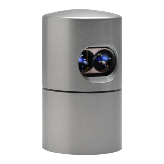
- Page 5 • A 41.3° vertical FOV • Usable returns up to 100 meters 360° Spinning LiDAR Sensor Figure 1. Overview of the LiDAR HDL-32E 3D Imaging System. HDL-32E User’s Manual 41.3° Valid Data Range 5 cm to 100 m [ 2 ]...
- Page 6 setuP This section describes the standard set up assuming you are connecting the sensor to a standard computer or laptop and mounting the sensor on a vehicle. For other connections and mounting locations, please contact Velodyne for technical assistance. The standard setup involves: 1.
- Page 7 set uP Connect Power and Computer The sensor units are commonly used in vehicle applications where standard 12 volt, 2 amp power is readily available. 1. Connect the interface module to power. 2. Connect the Ethernet connector to a standard PC or laptop RJ45 Ethernet port. Operate Before operating the sensor, make sure that: •...
- Page 8 usaG e The HDL-32E sensor needs no configuration, calibration, or other setup to begin producing usable data. Once the unit is mounted and wired, supplying it power will cause it to start scanning and producing data packets. The quickest way to watch the HDL-32E in action is to use Digital Sensor Recorder (DSR), the viewer software included with the unit.
- Page 9 usaG e Alternatively, the calibration data can be found in the included db.xml file found on the CD included with the HDL-32E. The calibration data for vertCorrection is the vertical correction angle for each laser, as viewed from the back of the unit and stated in degrees. Positive values have the laser pointing up and negative values have the laser pointing down.
- Page 10 usaG e External GPS Time Synchronization The HDL-32E can synchronize its data with precision GPS-supplied time pulses to enable users to ascertain the exact firing time of each laser in any particular packet. This capability requires a GPS receiver generating a sync pulse and the $GPRMC NMEA record over a dedicated RS-232 serial port. The output from the GPS receiver is connected to the HDL-32E.
- Page 11 usaG e HDL-32E User’s Manual The images below show the GPS receiver included with the HDL-32E. GPS EQUIPMENT HDL-32E Ethernet Cable AC Cord Garmin GPS-18LV GPS Receiver Power Adapter Interface Box GPS Interface Box Front & Back View Interface Box Interface Box Top View Front View...
- Page 12 usaG e Packet Format and Status Byte for GPS Time Stamping The 6 extra bytes at the end of the HDL-32E data packet are used to report GPS timing. For every packet, the last 6 bytes are formatted as follows: 4 bytes: 32 bit unsigned integer time stamp.
- Page 13 usaG e Laser Firing Sequence The laser firing order is the same as the order in the Ethernet packet. The most downward laser fires first, followed by the interleaved firings from the lower and upper “banks” of 16 lasers, as follows: Firing order The interleaving firing pattern is designed is to avoid and potential ghosting caused primarily by retro-reflectors.
- Page 14 tro uBLesHo o ti nG Use this chart to troubleshoot common problems with the HDL-32E. Problem Unit doesn’t spin Unit spins but no data serVi ce and M ai ntenance There are no user service or maintenance requirements or procedures for the Velodyne HDL-32E. For service or maintenance, please contact Velodyne at +1 (408) 465-2800, or log on to our website at www.velodynelidar.com.
- Page 15 sPeci fi cati o ns Laser: • Class 1 - eye safe • 905 nm wavelength • Time of flight distance measurement with intensity • Measurement range 100 m (5 cm to 100 m) • 32 laser/detector pairs • +10.67 to -30.67 degrees field of view (vertical) Sensor: •...
- Page 16 aPPendi x a: di G i taL senso r reco rder (dsr) Digital Sensor Recorder (DSR) DSR is a windows-based 3D point cloud visualization software program designed for use with the HDL-32E. This software is an “out of the box” tool for the rendering and recording of point cloud data from the HDL unit. You can develop visualization software using the DSR as a reference platform.
- Page 17 aPPendi x a HDL-32E User’s Manual Once the input of streaming data has been confirmed through the live playback feature, click on the Record button and the program will request the name and location for the pcap file to be created. Recording will begin immediately once the file information has been entered. Click on the Record button again to discontinue the capture.
- Page 18 aPPendi x a DSR Key Controls Zoom: Z = Zoom in Shift, Z = Zoom out Z Axis Rotation: Y = Rotate CW Shift, Y = Rotate CCW X Axis Rotation: P = Rotate CW Shift, P = Rotate CCW Y Axis Rotation: R = Rotate CW Shift, R = Rotate CCW...
- Page 19 aPPendi x B: HdL-3 2 e saM PLe data PacKets HDL-32E User’s Manual Data Packet Format The HDL-32E outputs two UDP Ethernet packets — a data packet containing laser firing data located on Port 2368 and a positioning packet which contains GPS and positioning data located on Port 8308. The packet at Port 2368 contains a header, a data payload of firing data and status data.
- Page 20 aPPendi x B HDL-32E User’s Manual User Datagram Protocol (UDP) Ethernet Data Packet Format: HDL-32E (Port 2368) Start identifier OxEEFF 2 mm increments (0 = no return within 100 m) Blank Blank Figure B1. [ 17 ]...
- Page 21 aPPendi x B HDL-32E User’s Manual Positioning Packet Using outputs from onboard gryrometers and 2 axis accelerometers, orientations shown below in Figure B2, the positioning ethernet Packet provides motion data (rotational and acceleration) for the stationary base of the HDL 32E unit. See the User Datagram Protocol (UDP) Positioning Ethernet Packet Format: HDL 32E, Figure B3, for interpretation of data output.
- Page 22 aPPendi x B HDL-32E User’s Manual Figure B3. [ 19 ]...
- Page 23 aPPendi x B HDL-32E User’s Manual Time Stamp: “7c bd 9c 91” 2442968444(919cbd7c hex)usec = 2442.9sec Time stamp from the head of the hour in usec. Sentence: “$GPRMC, 214042, A, 3708.3087, N, 12139.5146W, 000.0, 000.0, 160311, 014.8, E, A*0C” [ 20 ]...
- Page 24 aPPendi x B HDL-32E User’s Manual Ethernet Packet Example Captured via Wireshark. [ 21 ]...
- Page 25 aPPendi x c: co o rdi nate caLcuLati o n aLG o ri tHM saM PLe co de Coordinate Calculation Algorithm Sample Code After removing all the correction parameters except vertical correction, the calculation code is: firingData::computeCoords(guint16 laserNum, boost::shared_ptr<CalibrationDB> db, GLpos_t &pos) guint16 idx = laserNum % VLS_LASER_PER_FIRING;...
- Page 26 aPPendi x d: caLi Brati o n and o ri entati o n HDL-32E User’s Manual Calibration and Orientation There are six axes of variation when determining the exact location of any given laser firing for the HDL-32. The axes are x, y, z, along with rotational, horizontal, and vertical angles.
- Page 27 aPPendi x e: etHernet transi t ti M i nG taBLe HDL-32E User’s Manual [ 24 ]...
- Page 28 Velodyne LiD R, Inc. 345 Digital Drive Morgan Hill, CA 95037 408.465.2800 voice 408.779.9227 fax 408.779.9208 service fax www.velodynelidar.com Service Email: lidarservice@velodyne.com Sales Email: lidar@velodyne.com All Velodyne products are made in the U.S.A. Specifications subject to change without notice Other trademarks or registered trademarks are property of their respective owner. 63-9113 Rev PR2011...
Need help?
Do you have a question about the LIDAR HDL-32E and is the answer not in the manual?
Questions and answers