
Related Manuals for ESAB CIGWELD CutSkill 60


Summary of Contents for ESAB CIGWELD CutSkill 60
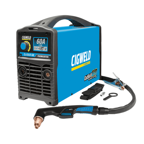
- Page 1 CutSkill 60 OPERATING MANUAL OUTPUT CURRENT CUTSKILL 60A CLEAN CUT WARRANTY* WARRANTY* mild steel 1.1mm tip PLASMA TORCH P/N:1-1601-60 Version No: AA Issue Date: 16-07-2019 Manual No: 0-5574...
- Page 2 YOU ARE IN GOOD COMPANY! The Brand of Choice for Contractors and Fabricators Worldwide. CIGWELD is a Market Leading Brand of Arc Welding Products for ESAB. We are a mainline supplier to major welding industry sectors in the Asia Pacific and emerging global markets including; Manufacturing, Construc- tion, Mining, Automotive, Engineering, Rural and DIY.
- Page 3 While the information contained in this Manual represents the Manufacturer’s best judgement, the Manufacturer assumes no liability for its use. CIGWELD CutSkill 60 Plasma Cutters Instruction Manual Number 0-5574 for: Part Number 1-1601-60 Published by:...
- Page 4 CutSkill 60 OPERATING MANUAL Be sure this information reaches the operator. You can get extra copies through your supplier. CAUTION These INSTRUCTIONS are for experienced operators. If you are not fully familiar with the principles of operation and safe practices for arc welding and cutting equipment, we urge you to read our booklet, “Precautions and Safe Practices for Arc Welding, Cutting, and Goug- ing,”...
- Page 5 DECLARATION OF CONFORMITY According to The Arc Welding Power Source Directive AS 60974.1-2006 (equivalent to IEC 60974-1 Ed. 2.1) The EMC Directive IEC 60974-10:2014 published on 06 February 2014 Type of equipment Plasma Cutting Power Source Type designation etc. Cutting Performance Brand name or trade mark Cigweld Manufacturer or his authorised representative established within the EEA...
-
Page 6: Table Of Contents
TABLE OF CONTENTS SECTION 1: GENERAL INFORMATION ................1-1 1.01 Notes, Cautions and Warnings ................ 1-1 1.02 Important Safety Precautions ................. 1-1 1.03 Publications ....................1-2 SECTION 2 SYSTEM: INTRODUCTION ..................2-1 2.01 Working Principle ................... 2-1 2.02 Power Supply Specifications ................2-1 2.03 Generator Recommendation ................ - Page 7 TABLE OF CONTENTS APPENDIX 1: CIRCUIT DIAGRAM .................. A-1 CIGWELD - LIMITED WARRANTY TERMS ..............1 WARRANTY SCHEDULE – CUTSKILL 60 ..............2...
- Page 8 This Page Intentionally Blank...
-
Page 9: General Information
CutSkill 60 OPERATING MANUAL • Keep all fumes and gases from the breathing area. SECTION 1: Keep your head out of the welding fume plume. GENERAL INFORMATION • Use an air-supplied respirator if ventilation is not adequate to remove all fumes and gases. • The kinds of fumes and gases from the plasma arc 1.01 Notes, Cautions and Warnings depend on the kind of metal being used, coatings on the metal, and the different processes. You Throughout this manual, notes, cautions, and warn- must be very careful when cutting or welding any ings are used to highlight important information. -
Page 10: Publications
CutSkill 60 OPERATING MANUAL • Use the shade of lens as suggested in the follow- WARNING ing per ANSI/ASC Z49.1: Fire and explosion can be caused by hot slag, Minimum Suggested sparks, or the plasma arc. Arc Current Protective Shade No. (Amperes) Shade No. (Comfort) • Be sure there is no combustible or flammable ma- Less than 20* terial in the workplace. - Page 11 CutSkill 60 OPERATING MANUAL 7. AWS Standard A6.0, WELDING AND CUTTING CONTAINERS WHICH HAVE HELD COMBUSTIBLES, obtainable from American Welding Society, 550 N.W. LeJeune Rd, Miami, FL 33126 8. NFPA Standard 51, OXYGEN-FUEL GAS SYSTEMS FOR WELDING, CUTTING AND ALLIED PROCESSES, obtainable from the National Fire Protection Associa- tion, Batterymarch Park, Quincy, MA 02269 9.
- Page 12 CutSkill 60 OPERATING MANUAL This Page Intentionally Blank GENERAL INFORMATION 0-5574...
-
Page 13: Section 2 System
CutSkill 60 OPERATING MANUAL SECTION 2 SYSTEM: INTRODUCTION 2.01 Working Principle Inverter Transformer Rectifier Compressed air Reduce pressure, Filter Gas Valve Cutting Torch Workpiece A-13679 2.02 Power Supply Specifications Power Supply Specifications Description CutSkill 60 Input Power 240 VAC (± 15%), Single-Phase, 50/60 Hz Output Current 20-60 Amps, continuously 35 Amps... -
Page 14: Generator Recommendation
CutSkill 60 OPERATING MANUAL 15.8kg A-13882 Figure 2-1: Power Supply Dimensions & Weight NOTE Weight includes torch & leads, input power cord, and work cable with clamp. CAUTION Provide clearance for proper air flow through the power supply. Operation without proper air flow will inhibit proper cooling and reduce duty cycle.. -
Page 15: Power Supply Controls And Features
CutSkill 60 OPERATING MANUAL 2.05 Power Supply Controls and Features A-13883 Figure 2-2: CutSkill 60 1. Plasma Cutting Torch Adaptor The plasma cutting torch adaptor is the connection point for the plasma cutting torch. Connect the torch by pushing the torch connector into the brass torch adaptor firmly and screwing the plastic torch nut clockwise to secure in position. - Page 16 CutSkill 60 OPERATING MANUAL 2. Control Knob Turn or press the Control Knob to select from the menu or change values. To adjust the cutting current: • Turn clockwise to increase cutting current; • Turn anti-clockwise to decrease cutting current. NOTE In gouging mode, the maximum output current is limited to 50A. To select an option from the displayed menu: • Options will be highlighted in sequence at every turn; • Turn clockwise or anti-clockwise to change selection; • Press the Control Knob to confirm the selection;...
-
Page 17: Lcd Screen Operation
CutSkill 60 OPERATING MANUAL NOTE For a secure seal, apply thread sealant to the fitting threads, according to manufacturer's instructions. Do Not use Teflon tape as a thread sealer, as small particles of the tape may break off and block the small gas passages in the torch. 7. - Page 18 CutSkill 60 OPERATING MANUAL 3. Menu Screen Press the Control Knob to enter Menu Screen. In Menu Screen, the user can set trigger mode, cutting mode, and gas purge. Exit Menu Screen by selecting Home icon. Trigger Mode Cutting Mode Gas Purge Home Icon Figure 2-8: Menu Screen 1) Trigger Mode Selection Screen Press the Control Knob when Trigger Mode section is highlighted to enter 2T/4T selection screen. Figure 2-9: Trigger Mode Screen Selected Turn the Control Knob clockwise or anti-clockwise to change the selection between 2T and 4T, and press the Control Knob to confirm the selection. Press the Control Knob again to exit Trigger Mode Selection Screen.
- Page 19 CutSkill 60 OPERATING MANUAL 2) Cutting Mode Selection Screen Turn the Control Knob clockwise and press when Cutting Mode is highlighted to enter Cutting Mode Selection Screen. Figure 2-12: Cutting Mode Selected Turn the Control Knob clockwise or anti-clockwise to change the selection among Plate mode, Grid mode and Gouging mode. Press the Control Knob to confirm the selection. Press the Control Knob again to exit Cutting Mode Selection Screen. Figure 2-13: Plate Mode Selected Figure 2-14: Grid Mode Selected Figure 2-15: Gouging Mode Selected NOTE Please note that when trigger mode is set at 4T, both Gouging mode and Grid cutting mode are unavailable.
- Page 20 CutSkill 60 OPERATING MANUAL 3) Gas Purge Screen Turn the Control Knob clockwise and press when Gas Purge Screen is highlighted to enter Gas Purge Screen. Figure 2-16: Gas Purge Screen Selected Press the Control Knob to turn ON or turn OFF gas purge function. When gas purge is turned ON, air pressure value is displayed in gas purge section. Gas valve is engaged and compressed air goes through the plasma torch. Press the Control Knob again to stop gas purge. Figure 2-17: Gas Purge Selected 4) Home Screen Turn the Control Knob clockwise and press when Home icon is highlighted to enter Home Screen. Press the Control Knob again to exit Menu Screen.
- Page 21 CutSkill 60 OPERATING MANUAL 5. Electrode or Cutting/Gouging Tip Installation Error Screen Electorde or Cutting/Gouging Tip Installation Error Screen displays when the electrode or cutting/gouging tip is not installed correctly. Gas will flow for 2 seconds then stop for 3 seconds. The power source continues to check the status of electrode and cutting/ gouging tip until they are in correct position.
- Page 22 CutSkill 60 OPERATING MANUAL 8. Over Temperature Error This cutting power source is protected by a temperature sensor. The Over Temperature Error screen will be displayed if the machine has over heated which normally occurs if the duty cycle of the power source has been exceeded.
-
Page 23: Section 2 Torch
CutSkill 60 OPERATING MANUAL SECTION 2 TORCH: F. Torch Ratings CutSkill 60A Torch Ratings INTRODUCTION Ambient 40 °C Temperature Rated Current 60 Amps 2T.01 Scope of Manual Duty Cycle This manual contains descriptions, operating instruc- Rated Voltage 500 V tions and maintenance procedures for the CutSkill 60A Operating Pressure 400-600 kPa Plasma Cutting Torch. -
Page 24: 03 Introduction To Plasma
CutSkill 60 OPERATING MANUAL B. Gas Distribution 2T.03 Introduction to Plasma The single gas used is internally split into plasma A. Plasma Gas Flow and secondary gases. Plasma is a gas which has been heated to an The plasma gas flows into the torch through the extremely high temperature and ionized so that it negative lead, through the starter cartridge, around becomes electrically conductive. -
Page 25: Installation
CutSkill 60 OPERATING MANUAL SECTION 3: INSTALLATION 3.01 Unpacking 1. Use the packing lists to identify and account for each item. A. Contents List Description Quantity Power Source CutSkill 60A Torch Work Cable and Clamp (3m) Shoulder Strap Nitto Air Fitting Nipple, Male Plug - 1/4" Wrench for Air Filter Operating Manual Gouging Tip 60A... -
Page 26: Primary Input Power Connections
CutSkill 60 OPERATING MANUAL 3.03 Primary Input Power Connections CAUTION Check your power source for correct voltage before plugging in or connecting the unit. The primary power source, fuse, and any extension cords used must conform to local electrical code and the recommended circuit protection and wiring require- ments as specified in Section 2. -
Page 27: Air Supply Connections
CutSkill 60 OPERATING MANUAL 3.04 Air Supply Connections A. Connecting Air Supply to Unit 1. Remove the red protective cap on the inlet port. 2. Connect the Nitto Air Fitting Nipple, Male Plug - 1/4" to the inlet port, or use other barb to connect to the inlet port. - Page 28 CutSkill 60 OPERATING MANUAL C. Installing Optional Inline Filter An optional inline filter (P/N CSP337039) is recommended for improved filtering with compressed air and keep- ing moisture or debris out of the torch. 1. Attach the inline filter hose to the Inlet Port 1/4" NPT of the system filter. 2.
-
Page 29: Work Lead Connection
CutSkill 60 OPERATING MANUAL 3.05 Work Lead Connection Connect the Work Lead to the power supply and the work piece. 1. Attach the male dinse plug of the work lead to the dinse socket on the front panel (refer to 2.04.4) as shown in Figure 3-4. -
Page 30: Torch Connection
CutSkill 60 OPERATING MANUAL 3.06 Torch Connection Fit the CutSkill 60A plasma torch to the power source by pushing the male torch connector into the female torch adaptor and screwing the torch locking nut clockwise to secure the plasma torch to the torch adaptor. CutSkill 60A Plasma Torch A-13884 Figure 3-5: Connecting Plasma Torch... -
Page 31: Section 4 System
CutSkill 60 OPERATING MANUAL SECTION 4 SYSTEM: OPERATION 4.01 Preparations for Operating At the start of each operating session: WARNING Disconnect primary power at the source before assembling or disassembling power supply, torch parts, or torch and leads assemblies. A. Torch Parts Selection Check the torch for proper assembly and appropriate torch parts. - Page 32 CutSkill 60 OPERATING MANUAL C. Check Primary Input Power Source 1. Check the power source for proper input voltage. Make sure the input power source meets the power requirements for the unit per Specifications in Section 2. 2. Connect the input power cable (or close the main disconnect switch) to supply power to the system. 240V AC Power Source Note: For maximum duty cycle to be achieved, Supply Plug and Lead must be upgraed to...
-
Page 33: Sequence Of Operation
CutSkill 60 OPERATING MANUAL 4.02 Sequence of Operation The following is a typical sequence of operation for this power supply. Refer to Appendix 1 for block diagram. 1. Plug the input power cord into an active circuit. 2. Switch the ON / OFF switch on the rear panel of the power source to ON position. Ensure the LCD illumi- nates. -
Page 34: Gouging
CutSkill 60 OPERATING MANUAL 9. Hold the torch perpendicular to the workpiece with the front of the tip on the edge of the workpiece at the point where the cut is to start. Pull the trigger. Arc is initiated and cutting process starts. Recom- mend always start the cutting from the edge of the work piece. -
Page 35: Cut Quality
CutSkill 60 OPERATING MANUAL Lead Angle 4.04 Cut Quality The angle between the torch and workpiece depends NOTE! on the output current setting and torch travel speed. Cut quality depends heavily on setup and pa- The recommended lead angle is 35°. At a lead rameters such as torch standoff, alignment with angle greater than 45°... -
Page 36: General Cutting Information
CutSkill 60 OPERATING MANUAL Bottom Dross Buildup Edge Starting Molten material which is not blown out of the cut For edge starts, hold the torch perpendicular to the area and resolidifies on the plate. Excessive dross workpiece with the front of the tip near (not touch- may require secondary cleanup operations after ing) the edge of the workpiece at the point where cutting. -
Page 37: Common Cutting Faults
CutSkill 60 OPERATING MANUAL 4.06 Common Cutting Faults Problem - Symptom Common Cause 1. Cutting speed too fast. 2. Torch tilted too much. 3. Metal too thick. Insufficient Penetration 4. Worn torch parts 5. Cutting current too low. 6. Non - Genuine Cigweld parts used 7. - Page 38 CutSkill 60 OPERATING MANUAL This Page Intentionally Blank OPERATION 0-5574...
-
Page 39: Section 5 System
CutSkill 60 OPERATING MANUAL SECTION 5 SYSTEM: SERVICE 5.01 General Maintenance Maintain more often Warning! if used under severe Disconnect input power before maintaining. conditions Each Use Press the water release valve Visual check of upward to release water torch tip and electrode from the water catchment. -
Page 40: Basic Troubleshooting Guide
CutSkill 60 OPERATING MANUAL A. Every three months Check external air filter, replace if necessary. 1. Shut off input power; turn off the gas supply. Bleed down the gas supply. Check air filter and replace if neces- sary. NOTE Leave internal ground wire in place B. - Page 41 CutSkill 60 OPERATING MANUAL PROBLEM CAUSE REMEDY Electrode or cutting Electrode or tip is not installed Reinstall the electrode or tip. tip installation error correctly. Electrode or tip is seriously Replace worn electrode or tip. worn. Plasma torch failure. Have an accredited CIGWELD service provider repair or replace.
- Page 42 CutSkill 60 OPERATING MANUAL This Page Intentionally Blank SERVICE 0-5574...
-
Page 43: Parts List
CutSkill 60 OPERATING MANUAL SECTION 6: PARTS LIST The parts list provides a breakdown of all replaceable components. 6.01 Power Source Replacement Parts Item # Description Catalog # Panel Cover CSP337097 PCB Inverter CSP337098 Panel Base CSP337099 Panel Front CSP337019 Dinse Socket CSP337020 Centre Adaptor... -
Page 44: Cutskill 60A Plasma Torch (P/N Csp337000) Replacement Parts
CutSkill 60 OPERATING MANUAL 6.02 CutSkill 60A Plasma Torch (P/N CSP337000) Replacement Parts Item # Description Catalog # Cutting Tip, 1.1mm CSP337095 Electrode CSP337003 Standoff Guide CSP337004 Shield Cap CSP337005 O-ring CSP337006 Diffuser CSP337007 Torch Handle CSP337008 Trigger Guard CSP337009 Torch Trigger CSP337010 Torch Head... - Page 45 CutSkill 60 OPERATING MANUAL APPENDIX 1: CIRCUIT DIAGRAM 0-5574 APPENDIX...
- Page 46 This Page Intentionally Blank.
- Page 47 CutSkill 60 OPERATING MANUAL CIGWELD - LIMITED WARRANTY TERMS LIMITED WARRANTY: CIGWELD Pty Ltd, An ESAB Brand, hereafter, “CIGWELD” warrants to customers of its autho- rized distributors hereafter “Purchaser” that its products will be free of defects in workmanship or material. Should any failure to conform to this warranty appear within the time period applicable to the CIGWELD products as stated below, CIGWELD shall, upon notification thereof and substantiation that the product has been stored, installed, oper- ated, and maintained in accordance with CIGWELD’s specifications, instructions, recommendations and recognized...
- Page 48 CutSkill 60 OPERATING MANUAL WARRANTY SCHEDULE – CUTSKILL 60 WARRANTY WARRANTY PERIOD – (Parts and Labour) CUTSKILL 60 3 Years ACCESSORIES WARRANTY PERIOD Plasma torch and work lead 3 Months Plasma torch consumable items CIGWELD Limited Warranty does not apply to; - Obsolete goods sold at auction, second-hand goods and prototype goods.
- Page 49 CutSkill 60 OPERATING MANUAL This Page Intentionally Blank...
- Page 50 CIGWELD Pty Ltd Singapore - Malaysia - Indonesia - CIGWELD An ESAB Brand ESAB Asia Pacific No 14 Jalan Teknologi 3/1 JI. Pulogadung No. 45 71 Gower Street, Preston VIC 3072 Australia 38 Joo Koon Circle Selangor Science Park 1...
Need help?
Do you have a question about the CIGWELD CutSkill 60 and is the answer not in the manual?
Questions and answers