Table of Contents
Advertisement
Quick Links
Advertisement
Table of Contents

Related Manuals for Fitness Reality X CLASS 410 ST


Summary of Contents for Fitness Reality X CLASS 410 ST
- Page 1 410 ST SMART TECHNOLOGY RECUMBENT BIKE IMPORTANT: Read all instructions carefully before using this product. Retain this owner’s manual for future reference. The specifications of this product may vary from this photo, subject to change without notice. 2161.1-082517...
- Page 2 PLEASE DO NOT RETURN THIS PRODUCT TO THE STORE. STOP. Contact customer service if you have any questions regarding assembly or proper operation of the machine. Email us at: Service@paradigmhw.com Or call us at: 1-844-641-7920 Hours: 8:00 am to 5:00 pm (PST) Daily...
-
Page 3: Table Of Contents
TABLE OF CONTENT SERVICE ------------------------------------------------------------------------ LABEL PLACEMENT --------------------------------------------------------- IMPORTANT SAFETY GUIDELINES ------------------------------------- OVERVIEW DRAWING ---------------------------------------------------- PART LIST --------------------------------------------------------------------- HARDWARE & TOOLS PACK -------------------------------------------- ASSEMBLY -------------------------------------------------------------------- CONSOLE --------------------------------------------------------------------- ADJUSTMENTS --------------------------------------------------------------- TROUBLESHOOTING ------------------------------------------------------- TRANSPORT & STORAGE ------------------------------------------------ WARRANTY -------------------------------------------------------------------- PARTS REQUEST FORM---------------------------------------------------... -
Page 4: Service
SERVICE IMPORTANT: FOR NORTH AMERICA ONLY For damaged or defective product, questions, replacement parts or any other service support, please contact our customer service department by the below methods: For The Best Service, please Email: service@paradigmhw.com Response Time: 1-2 Business Days Emailing us with the information above will be the best method to receive a response during peak business hours Website:... -
Page 5: Label Placement
LABEL PLACEMENT... -
Page 6: Important Safety Guidelines
IMPORTANT SAFETY GUIDELINES Read all instructions before using the equipment. When using the equipment, basic precautions should always be followed. WARNING - To reduce the risk of injury to persons, read and under the following: Make sure your equipment is correctly assembled before you use it. Be sure all screws, nuts, and bolts are tightened prior to use. - Page 7 IMPORTANT SAFETY GUIDELINES Do not use this equipment if you have any of the following conditions or ailments: • Pregnancy • Extreme obesity • Middle ear infection • Hiatus hernia or Ventral hernia • Glaucoma, retinal detachment or conjunctivitis • Use of anticoagulants including Aspirin in high doses. •...
-
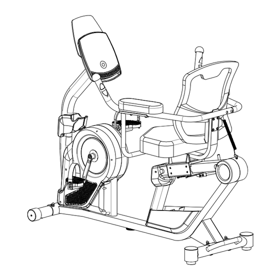
Page 8: Overview Drawing
OVERVIEW DRAWING... -
Page 9: Part List
PARTS LIST Description Q’ty Description Q’ty Main Frame Left Pedal Strap Front Post Rear Right Cover Seat Sliding Tube Rear Left Cover Right Handrail Support Tube Arm Rest Big Curved Washer Left Handrail Support Tube Ф6*Ф16*1.5 Right Handlebar Hex Bolt M6*50 Left Handlebar Socket Phillips Screw M6*15... - Page 10 PARTS LIST Description Q’ty Description Q’ty 59 Crank Cap Hex Bolt M6*15 60 Left Crank Spring 61 Protective Cover φ70*φ35*7 Hex Nut M6 62 Crank Cover Adjustable Rod 63 Screw ST4.2*20 Brake Adjustment 64 Self-Drilling Screw ST4.2*20 Hex Bolt M6*15 65 Right Cover Plastic Bushing 66 Bearing Cup...
-
Page 11: Hardware & Tools Pack
HARDWARE & TOOL PACK... -
Page 12: Assembly
ASSEMBLY Tools: 6mm Allen Wrench 1PC Discard (B) Discard (A) Step 1 1a. Remove the Metal Tubes from the Main Frame (1) by using 6mm Allen Wrench provided. 1b. Discard the metal tubes A and B and the associated hardware at that was removed. These parts are not needed for the assembly of the bike. - Page 13 ASSEMBLY Tool: Multi Hex Tool with Phillips Screwdriver Step 2 2a. Front Stabilizer Installation – Lift up the front of the Main Frame (1), and attach the Front Stabilizer (10) onto the front curve of the Main Frame (1) with two Carriage Bolts (23), two Curve Washers (22), two Spring Washers (15), and two Cap Nuts (21).
- Page 14 ASSEMBLY Tool: Multi Hex Tool with Phillips Screwdriver Step 3 3a. Installing the Left & Right Pedal Straps to the Pedals: Install the Left Pedal Strap (30) onto the Left Pedal (29). Install the Right Pedal Strap (28) onto the Right Pedal (27). See Figure A. 3b.
- Page 15 ASSEMBLY Tool: 6mm Allen Wrench Step 4 4a. Removal of Hardware for Installation: Remove four Flat Washers (16), seven Hex Bolts (14), seven Spring Washers (15) and three Curved Washers (17) from the Main Frame (1). 4b. Connecting the Pulse and Console Wires: Connect the Console Wire (12) from the Front Post (2) to the Lower Console Wire (19) from the Main Frame (1).
- Page 16 ASSEMBLY Tool: Multi Hex Tool with Phillips Screwdriver Step 5 5a. Left & Right Cup Holder Installation: Attach the Left and Right Cup Holder (18) & (48) onto the Front Post (2) with two Self-Drilling Screws (64) using the Multi Hex Tool with Phillips Screwdriver provided.
- Page 17 ASSEMBLY Tools: 6mm Allen Wrench 5mm Allen Wrench Step 6 6a. Removal of Hardware for Installation: Remove four Hex Bolts (38), four Spring Washers (15) and four Flat Washers (16) from the Main Frame (1). 6b. Installing the Seat Slide Tube: Attach the Seat Slide Tube (3) onto the Main Frame (1) by aligning the four holes on the Seat Slide Tube (3) and the Main Frame (1) using the previously removed four Hex Bolts (38), four Flat Washers (16), and four Spring Washers (15).
- Page 18 ASSEMBLY Tool: Multi Hex Tool with Phillips Screwdriver Step 7 7a. Installing the Left and Right Front Cover: Attach the Left Front Cover (25) and Right Front Cover (26) onto the Seat Slide Tube (3) with two Self-Drilling Screws (64). Align the edges of the covers and use one Screw (63) to secure both covers together.
- Page 19 ASSEMBLY Step 8 8a. Removing Hardware for Installation: Remove four Socket Phillips Screws (36) from the Seat Post (8). 8b. Handrail Support Tube Installation: Attach the both Right and Left Handrail Support Tubes (4) & (5) onto the Seat Post (8) with the four Socket Phillips Screws (36).
- Page 20 ASSEMBLY Tools: 5mm Allen Wrench 6mm Allen Wrench Multi Hex Tool with Phillips Screwdriver Step 10 S10, S13, S14, S15 1PC 10a. Installing the Left Handlebar and Backrest: Align the holes of the Backrest (44) and Left Handlebar (7) to the holes of the Seat Post (8). Secure the Backrest (44) and Left Handlebar (7) with four Hex Bolts (42), four Spring Washers (54) and four Flat Washers (43).
- Page 21 ASSEMBLY Tool: 6mm Allen Wrench Step 11 11a. Installing the Arm Rests: Attach both Arm Rest (33) to the Right/Left Handlebars (6) & (7) and Right/Left Handrail Support Tubes (4) & (5) with four Hex Bolts (35) and four Big Curved Washers (34).
- Page 22 ASSEMBLY Tool: Multi Hex Tool with Phillips Screwdriver Step 12 12a. Removal of Hardware for Installation: Remove the four Phillips Screws (107) from the back of the Console (11). 12b. Connecting the Console Wires: Connect the Console Wire (12A) from the Front Post (2) to the Upper Console Wire (12B) from the Console (11).
- Page 23 ASSEMBLY Step 13 13. Installing the Power Adaptor: Plug the small end of the Adaptor (24) into the Adaptor Wire (103) located on the front of the Right Cover (65).
-
Page 24: Console
CONSOLE 1. Button Functions START: 1. Begins the desired workout. 2. Resumes a paused workout session. STOP: 1. While exercising, press to pause a workout. 2. While paused, press to end the workout. 3. Press and hold for 3 seconds to reset the console. - Page 25 CONSOLE GENERAL FUNCTIONS: Use the UP or DOWN buttons to navigate the console options: PROGRAMS, and USERS then press OK to continue through each of the function's options. QUICK START: When the console first turns on you can enter a QUICK START work out by immediately pushing the START button at the main screen.
- Page 26 CONSOLE CUSTOM: Customized Programs 1. At the main screen use the UP or DOWN buttons to navigate to the “PROGRAMS” selection, then press OK. 2. Use the UP or DOWN buttons to navigate to “CUSTOM”, then press OK to confirm the selection.
- Page 27 CONSOLE Users: User Selection 1. At the main screen use the UP or DOWN buttons to navigate to the “USERS” selection, then press OK. 2. Use the UP or DOWN buttons to navigate to between User1 through User4 and press OK. 3.
-
Page 28: Adjustments
ADJUSTMENTS Adjusting the Seat Forward or Back 1. To adjust the seat to your height, move the Adjustable Rod (89) forward to release the Seat Post (8). 2. Adjust the seat to a comfortable position and then move the Adjustable Rod (89) back to lock the Seat Post (8) into place. -
Page 29: Troubleshooting
TROUBLESHOOTING & MAINTENANCE TROUBLE SHOOTING 1. PROBLEM: The recumbent bike wobbles when in use. 1) SOLUTION: Turn the Adjustable Pads (47) on the Rear Stabilizer (9) or the Adjustable Leveler (72) on the bottom of the Main Frame (1) as needed to level the recumbent bike. 2. - Page 30 TROUBLESHOOTING & MAINTENANCE Problem Potential Cause Correction 1. The motor does not Motor Problems activate Symptoms include an unusually loud noise coming from the Motor, which means the Gears are NOT meshing correctly. Try reversing the resistance and try again. If this fails then contact customer service.
-
Page 31: Transport & Storage
TRANSPORT & STORAGE Transporting the Bike Lift the Rear Stabilizer (9) with both hands until the Wheels of the Front Stabilizer (10) make contact with the ground. Pull or push the bike to the desired work out area or storage area. Gently lowering the bike after transporting, and always maintain both hands on the handle of the Rear Stabilizer (9) while transporting. -
Page 32: Warranty
WARRANTY MANUFACTURER’S LIMITED WARRANTY Paradigm Health & Wellness warrants to the original purchaser that this product is free from defects in material and workmanship when used for the purpose intended, under the conditions that it has been installed and operated in accordance with Paradigm’s Owner’s Manual. -
Page 33: Parts Request Form
PARTS REQUEST FORM Paradigm Health & Wellness, Inc. EMAIL THIS FORM WITH YOUR RECEIPT OF PURCHASE TO Service@paradigmhw.com * NAME:_____________________________________________________________________________________ ADDRESS:__________________________________________________________________________________ CITY:________________________ STATE:_____________ ZIP:_______________________________________ TELEPHONE: (Day)______________________________________________________________________ (Night)_____________________________________________________________________ SERIAL#:___________________________________________________________________________________ MODEL#:___________________________________________________________________________________ PURCHASE DATE:___________________________________________________________________________ PLACE OF PURCHASE:_______________________________________________________________________ PART # DESCRIPTION “YOUR ORDER WILL BE PROCESSED WITHIN 3 BUSINESS DAYS” This form can also be faxed to #: 626-810-2166...
Need help?
Do you have a question about the X CLASS 410 ST and is the answer not in the manual?
Questions and answers