Table of Contents
Advertisement
Quick Links
Advertisement
Table of Contents

Related Manuals for Sky-Drones SmartAP PRO

Summary of Contents for Sky-Drones SmartAP PRO
- Page 1 Flight Control System User’s Guide www.sky-drones.com...
-
Page 2: Smartap Pro
All rights reserved... -
Page 3: Table Of Contents
Size and Weight Previous versions SmartAP PRO 2 SmartAP PRO 1 Installation Mounting the board Connections External GNSS / MAG SmartAP PRO 0.2 and later SmartAP PRO 0.1 and earlier GPS Receiver RC Receiver RSSI Monitoring Motors ESC Telemetry module OSD Video... - Page 4 Telemetry Module Power Module Electromagnetic sounder Camera trigger Assembled System Specifications Introduction Features Installation Pinout Soldering Powering the autopilot SmartAP PRO SmartAP MAX Buzzer support Voltage and current sensors Specifications Specifications Features Package includes Dimensions RTK GNSS Specifications Features Package includes...
- Page 5 SmartAP AutoPilot User’s Guide CONTENT Front Right Rear Bottom Ground Module Left Front Right Rear Bottom Installation Set content Preparing Air module Preparing Ground module Power supply Autopilot Initial power up Software Verify SmartLink was discovered Run Ground Station Software Manual control Change settings Accesing settings menu...
- Page 6 MicroDrones MD4-1000 Quadcopter T960 Hexacopter F450 Quadcopter 3DR Hexacopter Updating GNSS Module Getting U-Center RTK GNSS Configuration update SmartAP PRO Onboard GNSS module update Flashing Bootloader Tools required Connections Flashing Flashing DFU (old) Firmware and bootloader update via USB Modes overview...
- Page 7 SmartAP AutoPilot User’s Guide Introduction Gyroscope calibration Magnetometer calibration Flying with SmartAP GCS World Pane overview Getting the video feed Autonomous Flights Waypoints flight Guided flight Flying with RTK GNSS Locating the antenna Connecting in SmartAP GCS Starting Survey-In Survey-In completed RTK Modes Geotag images Logs analysis...
-
Page 8: Introduction
Introduction Sky-Drones - the leading manufacturer of autopilots and flight control systems solutions which can be applied to a wide range of Drones (UAVs) applications such as Surveying, Mapping, Inspection, Security, Safety and High-Quality Media production. The company has an outstanding background and experience in Research and Development, Manufacturing and Delivering products and solutions for extremely rapidly growing market in Drones / UAV segment. -
Page 9: Smartap Pro
SmartAP AutoPilot User’s Guide Introduction SmartAP PRO Industry leading Flight Control System with outstanding reliability, positioning precision and control accuracy for professional applications with various peripherals already integrated onboard SmartAP MAX Flight Control System aimed at the wide range of purposes for consumer and professional applications with the compact main core and externally... -
Page 10: Smartap Gnss
SmartAP AutoPilot User’s Guide Introduction SmartAP GNSS GPS/GLONASS receiver with integrated patch antenna, magnetometer and pressure sensor SmartAP RTK GPS/GLONASS RTK (Real-Time Kinematics) receiver for high-precision positioning SmartAP PDB Power Distribution Board for ESCs / Motors power supply and 5V / 12V generation... -
Page 11: Software
SmartAP AutoPilot User’s Guide Specifications Purchase the Hardware in official Sky-Drones Store Software SmartAP GCS (Ground Control Station) is the software application which allows you to plan and create autonomous missions for your SmartAP Autopilot as well as control the UAV using intuitive high-level commands. SmartAP GCS also includes Configurator. -
Page 12: Specifications
Specifications Introduction SmartAP PRO Autopilot is the latest generation of professional flight control system for multirotor Unmanned Aerial Vehicles capable of fully autonomous flight. It has a powerful microcontroller, multiple redundant 9-axis Inertial Measurement Unit (Gyroscopes, Accelerometers, Magnetometer) with temperature stabilization, integrated telemetry module, external GNSS module with the latest with integrated magnetometer. -
Page 13: Description
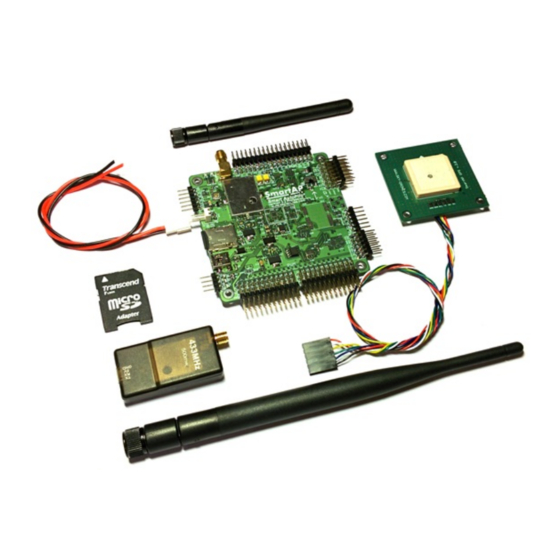
SmartAP AutoPilot User’s Guide Specifications 1. SmartAP PRO Flight Controller Main board 2. External GNSS / Magnetometer module 3. Ground telemetry module 4. Onboard telemetry antenna 5. High-gain ground telemetry antenna 6. Power input cable 7. MicroSD card with SD card adapter... -
Page 14: General
SmartAP AutoPilot User’s Guide Specifications General Powerful microcontroller 32 bit 168 MHz STM32F4 ARM Cortex M4 Compact board size of 8x8 cm (3.15"x3.15"), weight 60g, 6 layers PCB design Power supply from the main LiPO battery (3S - 14S) support, up to 60 Volts Power supply from BEC 5V support 12V, 5V, 3.3V generated onboard Integrated GNSS receiver UBlox NEO M8N, GPS/GLONASS, up to 24 sats, 10 Hz), active antenna... -
Page 15: Sensors
Pressure sensors: MS5611 Flight Modes Stabilization Altitude Hold Position Hold Return to Home Autonomous Waypoints Flight Guided Follow me Take off Landing Size and Weight Length: 80mm Width: 80mm Height: 17mm Weight: 39g Previous versions SmartAP PRO 2 SmartAP PRO 1... - Page 16 SmartAP AutoPilot User’s Guide Installation...
-
Page 17: Installation
Motors ESC Telemetry module OSD Video Electromagnetic sounder Power supply LED & Buzzer Pressure sensor foam Dimensions SmartAP PRO v .2 pinout SmartAP PRO v .1 pinout SmartAP PRO v .0 pinout SmartAP MAX SmartAP PDB SmartAP GNSS SmartLink Autopilot configuration... -
Page 18: External Gnss / Mag
External GNSS / MAG If you’re using external GNSS / Magnetometer module board then the connection should be as following: SmartAP PRO 0.2 and later GNSS / Magnetometer cable goes to dedicated GNSS / MAG port having 6 wires ( SmartAP PRO 0.1 and earlier... -
Page 19: Gps Receiver
SmartAP AutoPilot User’s Guide Installation Make sure to place GPS module as far as possible from: Main body of the airframe RF emitting devices such as transmitters High-current cables (ESC / motors power supply) GPS Receiver Connect GPS antenna to GPS antenna port. This is only for the versions which have integrated GNSS module. RC Receiver After mounting the board you need to connect cables from RC Receiver to SmartAP PPM / SBUS Input. -
Page 20: Rssi Monitoring
SmartAP AutoPilot User’s Guide Installation connect S.Port wire from receiver to pin next to SBus input. Channels assignments should normally be as following: Input channel 1 – Roll Input channel 2 – Pitch Input channel 3 – Throttle Input channel 4 – Yaw Input channel 5 –... -
Page 21: Electromagnetic Sounder
Connect Electromagnetic sounder to BUZ port of SmartAP. Power supply Connect power supply cable from main power distribution board of the UAV: SmartAP PRO 0.1 and earlier: 10-36 V, 3S – 8S SmartAP PRO 0.2 and later: 10-60 V, 3S – 14S LED & Buzzer Buzzer: 12V, 0.2A (included in the kit) LED 1-4: 12V, 0.2A per each channel (enough to power LED strip of 25cm length) -
Page 22: Dimensions
SmartAP AutoPilot User’s Guide Installation Dimensions Dimensions of the board are 80x80 mm. Mounting holes diameter is 3 mm, distance between the center of the mounting hole and board edges is 4.5 mm. SmartAP PRO v .2 pinout... -
Page 23: Smartap Pro V .1 Pinout
SmartAP AutoPilot User’s Guide Installation SmartAP PRO v .1 pinout... -
Page 24: Smartap Pro V .0 Pinout
SmartAP AutoPilot User’s Guide Installation SmartAP PRO v .0 pinout... - Page 25 SmartAP AutoPilot User’s Guide Specifications...
-
Page 26: Specifications
SmartAP AutoPilot User’s Guide Specifications Introduction SmartAP PRO SmartAP MAX Specifications Introduction Set includes Description Flight performance General Processor Sensors Flight Modes Interfaces Size and Weight Installation SmartAP PDB SmartAP GNSS SmartLink Autopilot configuration Flying Support Revision history Specifications Introduction SmartAP MAX Autopilot is the latest generation flight control system for multirotor Unmanned Aerial Vehicles of various configurations and sizes aimed at the wide range of applications. -
Page 27: Set Includes
SmartAP AutoPilot User’s Guide Specifications Set includes 1. SmartAP MAX Flight Controller 2. GPS / GLONASS satellite navigation module with integrated 3-axis magnetometer 3. Telemetry kit (air and ground module with antennas and connection cable) 4. DC-DC Power module and current / voltage sensor 5. -
Page 28: Sensors
SmartAP AutoPilot User’s Guide Installation 32 bit 168 MHz ARM Cortex M4 Hardware FPU 2 MB Flash 192 kB RAM Sensors Vibration dampened multiple redundant temperature stabilized IMU 2x 9-axis IMU InvenSense MPU-9250 (accelerometer, gyroscope, magnetometer) 2x Pressure sensor MS5611 (integrated and external) 1x 3-axis magnetometer HMC5883 (external) 1x UBlox M8N GPS Module (external) Flight Modes... -
Page 29: Installation
SmartAP AutoPilot User’s Guide Installation Introduction SmartAP PRO SmartAP MAX Specifications Installation Mounting the System Autopilot GNSS / MAG Connecting Peripherals RC Receiver ESC / Motors PWM GNSS / MAG Telemetry Module Power Module Electromagnetic sounder Camera trigger Assembled System... -
Page 30: Gnss / Mag
SmartAP AutoPilot User’s Guide Installation GNSS / MAG GNSS Module provides positioning information to the system and is sensitive to EMI noise. Make sure to place GNSS module as far as possible from: Main body of the airframe RF emitting devices, such as video transmitters High-current cables (ESC / motors power supply) It’s recommended to use GPS mast for that. -
Page 31: Plastic Case Version
SmartAP AutoPilot User’s Guide Installation Plastic case version Front panel connectors pinout: Rear panel connectors pinout: Make sure NOT to mix up polarity. GND line (black) is always near edge (bottom) RC Receiver Connect PPM / SBUS output of the RC receiver to PPM / SBUS Input port of SmartAP. ESC / Motors PWM Connect ESC cables to SmartAP PWM outputs 1-12 depending on the number of the motors your airframe has. -
Page 32: Gnss / Mag
SmartAP AutoPilot User’s Guide Installation PWM signals is the top wire, GND is the bottom one. If you can’t find your airframe in the list above, please, let us know and we’ll add your airframe! GNSS / MAG Connect the one side of the cable to GNSS module and the other one to the GPS / MAG port of the autopilot as shown on the pictures below: Telemetry Module Connect the one side of the cable to air telemetry module and the other one to the RADIO port of the autopilot as shown on the pictures below: Power Module... -
Page 33: Camera Trigger
SmartAP AutoPilot User’s Guide Installation Camera trigger SmartAP MAX supports automated camera triggering interface which physically be: PWM Output - if you want to use PWM output, simply connect camera trigger activator into any free PWM channel and configure port number later in the settings. - Page 34 SmartAP AutoPilot User’s Guide Specifications...
-
Page 35: Specifications
SmartAP AutoPilot User’s Guide Specifications Introduction SmartAP PRO SmartAP MAX SmartAP PDB Specifications Introduction Features Installation SmartAP GNSS SmartLink Autopilot configuration Flying Support Revision history Specifications Introduction SmartAP PDB (Power Distribution Board) is a special board which allows transferring the power from the battery to ESCs / Motors and generate power supply for the flight controller and other peripherals with different voltage levels. - Page 36 SmartAP AutoPilot User’s Guide Installation...
-
Page 37: Installation
SmartAP AutoPilot User’s Guide Installation Introduction SmartAP PRO SmartAP MAX SmartAP PDB Specifications Installation Pinout Soldering Powering the autopilot SmartAP PRO SmartAP MAX Buzzer support Voltage and current sensors SmartAP GNSS SmartLink Autopilot configuration Flying Support Revision history Installation SmartAP PDB - Power Distribution Board for Batteries / ESCs connection with integrated voltage and current sensors, buzzer, 5V and 12V... -
Page 38: Pinout
SmartAP AutoPilot User’s Guide Installation Pinout SmartAP Power Distribution Board pinout diagram is shown below. Big pads in the rear side are intended for the main battery connection. Up to four independent batteries can be connected using the thick wires (e.g. 8-10 AWG) to be able to handle high current loads and even more using thinner wires. -
Page 39: Powering The Autopilot
SmartAP PRO SmartAP PRO autopilot is capable of getting the power directly from the main battery, therefore, specially dedicated solder terminals can be used. If you would like the autopilot to get the current sensor (integrated in PDB) readings - simply connect the... -
Page 40: Smartap Max
SmartAP AutoPilot User’s Guide Installation WARNING! SmartAP 3.x gets power directly from the PDB connected to the main battery, therefore, supply voltage is the same as your battery voltage and it can be up to: 36V (8S) for SmartAP 3.0 36V (8S) for SmartAP 3.1 Wiring between the Power Distribution Board and the Autopilot should look as following: SmartAP MAX... -
Page 41: Buzzer Support
SmartAP AutoPilot User’s Guide Specifications Buzzer support SmartAP PDB has integrated electromagnetic buzzer (sounder) which is used for audio notifications about the system status. Simply connect the signals of the flight controller to signals of the PDB. BUZZER BUZZER Voltage and current sensors SmartAP PDB has integrated voltage and current sensors. -
Page 42: Specifications
SmartAP AutoPilot User’s Guide Specifications Introduction SmartAP PRO SmartAP MAX SmartAP PDB SmartAP GNSS Specifications Specifications Features Package includes Dimensions RTK GNSS SmartLink Autopilot configuration Flying Support Revision history Specifications Specifications SmartAP GNSS is a compact GPS/GLONASS module with integrated active antenna, UBlox Neo-M8N chipset and 3-axis magnetometer (compass). -
Page 43: Package Includes
SmartAP AutoPilot User’s Guide RTK GNSS Diameter 75 mm Weight 18g Fully compatible with SmartAP Autopilots Package includes GNSS Module Connection cable Dimensions... -
Page 44: Rtk Gnss
SmartAP AutoPilot User’s Guide RTK GNSS Introduction SmartAP PRO SmartAP MAX SmartAP PDB SmartAP GNSS Specifications RTK GNSS Specifications Features Package includes SmartLink Autopilot configuration Flying Support Revision history RTK GNSS Specifications This GNSS (GPS + GLONASS) module is base on RTK technology and was specially developed for SmartAP Autopilot and is intended to be used in applications where precise positioning really matters. -
Page 45: Package Includes
SmartAP AutoPilot User’s Guide Specifications Package includes Base station module Active patch antenna for base station module Airborne module with integrated patch antenna Connection cable... -
Page 46: Specifications
SmartAP AutoPilot User’s Guide Specifications Introduction SmartAP PRO SmartAP MAX SmartAP PDB SmartAP GNSS SmartLink Specifications Introduction Set includes Description Air Module Ground Module Interfaces Software Interfaces Installation Manual control Change settings API and SDK Other AP / GCS support... -
Page 47: Description
SmartAP AutoPilot User’s Guide Specifications 4. 2x Ground Module antennas 5. Power cable Description Air Module SmartLink Air is based on powerful quad-core ARM Cortex A53 SoC (system-on-chip) computer running Linux. The system is capable of handling two real time HD video streams from cameras, autopilot telemetry and control. It also has plenty of resources for user applications. Various interfaces e.g. - Page 48 SmartAP AutoPilot User’s Guide Interfaces Payload control joystick SmartAP GCS can be used on any platform and operating system including MacOS, Windows, iOS, Android and Linux. SmartAP GCS provides all status information on radio link including RSSI, SNR, packets and allows to dynamically change all major settings. For instance, operating frequency, bandwidth or power can be change just with a one click.
-
Page 49: Interfaces
SmartAP AutoPilot User’s Guide Interfaces Introduction SmartAP PRO SmartAP MAX SmartAP PDB SmartAP GNSS SmartLink Specifications Interfaces Air Module Left Front Right Rear Bottom Ground Module Left Front Right Rear Bottom Installation Manual control Change settings API and SDK Other AP / GCS support... -
Page 50: Left
SmartAP AutoPilot User’s Guide Interfaces Left 5V DC Power input socket Reset button USB for firmware upgrade SPI 0 / 1 I2C 0 / 1 UART 0 / 1 (console and autopilot telemetry) SPI 1 5V OUT SPI1 SCLK SPI1 MISO SPI1 MOSI SPI1 CS0 GND I2C 0 / 1 5V OUT I2C1 SCL I2C1 SDA I2C2 SCL I2C2 SDA GND UART 0 / 1... -
Page 51: Right
SmartAP AutoPilot User’s Guide Interfaces Front side has integrated fan. It's important to have clear space for air flow circulation in front of this side. Right Micro HDMI input 1 Micro HDMI input 2 Micro SD card slot Rear USB A connectors for peripherals connection, for instance: 4G / LTE Modem Rockblock satellite communication system FLARM ADSB system... -
Page 52: Bottom
SmartAP AutoPilot User’s Guide Interfaces Bottom Ground Module Front side has integrated fan. It's important to have clear space for air flow circulation in front of this side. -
Page 53: Left
SmartAP AutoPilot User’s Guide Interfaces Left TX: blinking when packets are being transmitted RX: blinking when packets are being received LNK: Ethernet / USB link established CPU: Module operating RSSI: Signal quality Front SMA antenna connectors... -
Page 54: Right
SmartAP AutoPilot User’s Guide Interfaces Right Reset button Rear USB to connect to computer / tablet Power supply, 7-35V DC... -
Page 55: Bottom
SmartAP AutoPilot User’s Guide Installation Bottom... -
Page 56: Installation
SmartAP AutoPilot User’s Guide Preparing Air module Introduction SmartAP PRO SmartAP MAX SmartAP PDB SmartAP GNSS SmartLink Specifications Interfaces Installation Set content Preparing Air module Preparing Ground module Power supply Autopilot Initial power up Software Verify SmartLink was discovered Run Ground Station Software... -
Page 57: Preparing Air Module
SmartAP AutoPilot User’s Guide Preparing Air module Ground module Air module Pair of antennas for air module Pair of antennas for ground module Power cable for ground module Power cable for air module Telemetry cable for the autopilot Preparing Air module First of all, attach antennas to the air module: It's not allowed to power up any of the modules without antennas! Powering up the modules without antennas may cause malfunction of the amplifier and permanent damage. - Page 58 SmartAP AutoPilot User’s Guide Preparing Ground module Here it is how air module should look like with power and telemetry cables connected: Connect one or two microHDMI cables to microHDMI port:...
-
Page 59: Preparing Ground Module
SmartAP AutoPilot User’s Guide Power supply Another side goes into HDMI port of the video source (camera): In this example we demonstrate GoPro Hero 6 video camera with 1080p@60fps video output. SmartLink is capable of capturing the following video source types: 1080p@60fps 1080p@30fps 720p@60fps... -
Page 60: Power Supply
SmartAP AutoPilot User’s Guide Autopilot By default, 8 dBi antennas comes with the set. Depending on your specific applications you might use different antennas designed for 2.4 GHz band. Connect micro USB cable and power cable to the ground module as shown on the image: Power supply Ground module supports any power supply source with the voltage in range from 10V to 50V. -
Page 61: Autopilot
SmartLink system is compatible with any autopilot which has TTL UART telemetry port. For instance, it's compatible with: SmartAP Autopilot Pixhawk series Autopilot APM series Autopilot other TTL UART telemetry port autopilots For this demonstration we use SmartAP MAX Autopilot from Sky-Drones:... - Page 62 SmartAP AutoPilot User’s Guide Initial power up Connect telemetry cable to Radio port of the autopilot as shown below: After completing the steps above you will have fully assembled air module:...
-
Page 63: Initial Power Up
SmartAP AutoPilot User’s Guide Software Before the first power up you have assembled air module and ground module as shown below: Initial power up Power up both ground module and air module. -
Page 64: Software
SmartAP AutoPilot User’s Guide Software It might take up to 15 seconds to both modules properly boot up and link to each other. By default, modules come pre-configured and paired. Transmission power is set to minimum. Ground module has status LEDs which allow to identify the current status of the system. Most important are RSSI LEDs: Three RSSI LEDs blinking altogether: RF off Three RSSI LEDs blinking in turn: Searching for pair One, two or three LEDs solid: RSSI status, more solid LEDs equals better signal... -
Page 65: Run Ground Station Software
Once you have everything connected and powered up you may start the ground station software. SmartLink is compatible with various popular ground control stations. In this demonstration we use SmartAP GCS by Sky-Drones. SmartLink is fully supported by SmartAP GCS. Start... - Page 66 SmartAP AutoPilot User’s Guide Software Enable the option , this will create SmartLink connection automatically. Autoconnect to SmartLink After that, go back to the pane and click button in the top right corner. You will see SmartLink connection added. If it's not World Connections added automatically or missing you may add it manually as shown below:...
- Page 67 SmartAP AutoPilot User’s Guide Software You can easily switch between full map and full video by just tapping on the video feed: Finally, full setup looks as follows:...
- Page 68 SmartAP AutoPilot User’s Guide Manual control...
-
Page 69: Manual Control
SmartAP AutoPilot User’s Guide Manual control Introduction SmartAP PRO SmartAP MAX SmartAP PDB SmartAP GNSS SmartLink Specifications Interfaces Installation Manual control Change settings API and SDK Other AP / GCS support Firmware update Troubleshooting Autopilot configuration Flying Support Revision history Manual control SmartLink allows to transmit manual control signal from any USB device (e.g. - Page 70 SmartAP AutoPilot User’s Guide Change settings Once you've selected the joystick you will be able to assign the channels according to your preferences. Make sure that Enable pilot joystick for is checked, otherwise manual control messages will not be sent. control Additionally, you can connect the second joystick which will be used for payload control.
-
Page 71: Change Settings
SmartAP AutoPilot User’s Guide Change settings Introduction SmartAP PRO SmartAP MAX SmartAP PDB SmartAP GNSS SmartLink Specifications Interfaces Installation Manual control Change settings Accesing settings menu Changing Radio settings Changing Security settings API and SDK Other AP / GCS support... -
Page 72: Changing Security Settings
SmartAP AutoPilot User’s Guide Change settings SNR - Signal Noise Ratio, the ratio of signal power to the noise power, expressed in decibels. RSSI - Received Signal Strength Indication, a measure of the energy observed by an antenna when receiving a signal It's recommended to keep output TX power for both air and ground module at low values when working with the system. - Page 73 SmartAP AutoPilot User’s Guide API and SDK...
-
Page 74: Api And Sdk
SmartAP AutoPilot User’s Guide API and SDK Introduction SmartAP PRO SmartAP MAX SmartAP PDB SmartAP GNSS SmartLink Specifications Interfaces Installation Manual control Change settings API and SDK Telemetry Video Manual Control Other AP / GCS support Firmware update Troubleshooting Autopilot configuration... -
Page 75: Manual Control
SmartAP AutoPilot User’s Guide Other AP / GCS support Manual Control Manual control comes as a part of other MAVLink telemetry messages. message from MAVLink specification is MANUAL_CONTROL recommended but not limited to. You may use any manual control message according to your specification, SmartLink will act as a transparent transfer layer just like any other telemetry module. -
Page 76: Other Ap / Gcs Support
SmartAP AutoPilot User’s Guide Other AP / GCS support Introduction SmartAP PRO SmartAP MAX SmartAP PDB SmartAP GNSS SmartLink Specifications Interfaces Installation Manual control Change settings API and SDK Other AP / GCS support QGroundControl Configuration settings Mission Planner Configuration settings... -
Page 77: Configuration Settings
SmartAP AutoPilot User’s Guide Firmware update Configuration settings Connection type: UDP Host: smartlink.local Port: 14555 Autopilot UART: 57600 8N1 3V3 TTL Video Use the following GStreamer pipeline to see the real time video in Mission Planner rtspsrc location=rtsp://smartlink.local:8554/camera/0 ! rtph264depay ! avdec_h264 ! videoconvert ! video/x-raw,format=BGRA ! appsink name=outsink sync=false... -
Page 78: Firmware Update
SmartAP AutoPilot User’s Guide Firmware update Introduction SmartAP PRO SmartAP MAX SmartAP PDB SmartAP GNSS SmartLink Specifications Interfaces Installation Manual control Change settings API and SDK Other AP / GCS support Firmware update Using Ubuntu: Get USB Boot utility (done only once) - Page 79 SmartAP AutoPilot User’s Guide Troubleshooting...
-
Page 80: Troubleshooting
SmartAP AutoPilot User’s Guide Troubleshooting Introduction SmartAP PRO SmartAP MAX SmartAP PDB SmartAP GNSS SmartLink Specifications Interfaces Installation Manual control Change settings API and SDK Other AP / GCS support Firmware update Troubleshooting Unable to ping smartlink.local - Unknown host... -
Page 81: Looking Up For Smartlink Ip Address
SmartAP AutoPilot User’s Guide Drivers installation cd "C:\Program Files (x86)\Nmap" Looking up for SmartLink IP address Execute IP addresses scan within the required range, in our case it will be: nmap 192.168.168.* As the result of this command you'll see IP addresses in this range. You'll have 192.168.168.1 which is as a rule configured as air module, 192.168.168.2 which is usually configured as ground module and 192.168.168.x (x: 0-255) which is IP address for SmartLink. -
Page 82: Drivers Installation
SmartAP AutoPilot User’s Guide Drivers installation Introduction SmartAP PRO SmartAP MAX SmartAP PDB SmartAP GNSS SmartLink Autopilot configuration Drivers installation Getting the software Firmware update General configuration Standard PID presets Updating GNSS Module Flashing Bootloader Flashing DFU (old) Flying Support... - Page 83 SmartAP AutoPilot User’s Guide Drivers installation you'll see SmartAP as unknown device. Manager If you can not see SmartAP bootloader in the devices list it's probably because the devices is hidden. To make bootloader device visible not only for initial three seconds after power up but for longer you can enable hidden devices in windows device manager using the steps below. Open CMD as administrator SET DEVMGR_SHOW_NONPRESENT_DEVICES=1 Type...
- Page 84 SmartAP AutoPilot User’s Guide Drivers installation Then choose . Go to the Download section of the website and get the driver .inf file for the autopilot. Browse my Computer for Driver Software Specify the location of the driver in menu. Browse When pop up window comes choose Install driver anyway...
- Page 85 SmartAP AutoPilot User’s Guide Drivers installation Once it's completed you can see the message that the driver was successfully installed. Unplug and plug in the USB cable of the autopilot to reboot the board and then if you go to you'll see that the driver is now Device Manager installed successfully:...
- Page 86 SmartAP AutoPilot User’s Guide Getting the software...
-
Page 87: Getting The Software
SmartAP AutoPilot User’s Guide Getting the software Introduction SmartAP PRO SmartAP MAX SmartAP PDB SmartAP GNSS SmartLink Autopilot configuration Drivers installation Getting the software First run Create account World pane App Menu UAV Settings Links Management First connection Firmware update... -
Page 88: First Run
SmartAP AutoPilot User’s Guide Getting the software Tablets Smartphones And available for the major operating systems: Windows MacOS Android Linux Depending on the version and platform you've chosen follow the steps to install the application. First run Run the applications after installation and if you're able to see the authorization window then it means that the application was installed successfully and you may proceed to the next steps. -
Page 89: World Pane
SmartAP AutoPilot User’s Guide Getting the software Please, use strong password containing at least 8 symbols with at least one digit. World pane Once you fill in the details click . If you're registered successfully you'll get into the app and will see the main pane which is called SIGN UP World. -
Page 90: Uav Settings
SmartAP AutoPilot User’s Guide Getting the software UAV Settings Clicking the gear will open UAV settings menu. The main tab shows information concerning hardware, installed firmware and unique ID. Tabs at left provide the navigation between various settings of the flight controller which will be described in the further chapters. Links Management Top right corner has Links icon. -
Page 91: First Connection
SmartAP AutoPilot User’s Guide Firmware update First connection Select the desired connection, click and then CONNECT If you have successfully created a proper connection, you will see the icons changing their state and hear confirmation that the UAV has been connected and parameters are being loaded. -
Page 92: Firmware Update
SmartAP AutoPilot User’s Guide Firmware update Introduction SmartAP PRO SmartAP MAX SmartAP PDB SmartAP GNSS SmartLink Autopilot configuration Drivers installation Getting the software Firmware update Latest firmware installation Custom firmware upload Getting the log General configuration Standard PID presets Updating GNSS Module... - Page 93 WHAT'S NEW UPGRADE The firmware will be downloaded from Sky-Drones cloud platform. Sometimes after pressing the button you might see the reboot request. Simply plug out and then plug in flight controller USB cable.
- Page 94 SmartAP AutoPilot User’s Guide Firmware update If the upgrade procedure still not started make sure you don't have any other serial (COM port) devices connected to computer. Once the procedure started you will see progress notification and status. Usually update procedure takes from 30 to 60 seconds. After upgrade procedure successfully finished you will see the confirmation message.
-
Page 95: Custom Firmware Upload
SmartAP AutoPilot User’s Guide Firmware update Custom firmware upload If you want to upload custom firmware you may do that by clicking Options icon (three dots) in the top-right corner. Simply click Custom Firmware , select the file you want to flash and follow further instructions. File Getting the log In case something is not going right during the firmware upgrade you might want to see the logs to further understand the issue or provide this... - Page 96 SmartAP AutoPilot User’s Guide General configuration...
-
Page 97: General Configuration
SmartAP AutoPilot User’s Guide General configuration Introduction SmartAP PRO SmartAP MAX SmartAP PDB SmartAP GNSS SmartLink Autopilot configuration Drivers installation Getting the software Firmware update General configuration General Airframe System orientation Landing Gear Motors IDLE speed Radio Sensors Accelerometer calibration... -
Page 98: Airframe
SmartAP AutoPilot User’s Guide General configuration Airframe Airframe tab allows you to configure the type of your vehicle. Click and choose your airframe from the list. If you can’t see your airframe there – feel free to contact us and we’ll add the new AIRFRAME airframe type for you. -
Page 99: System Orientation
SmartAP AutoPilot User’s Guide General configuration Channels mapping and propellers rotation are shown on the corresponding images. System orientation You can choose the desired orientation of the flight controller and GNSS Module from corresponding orientation menus. Landing Gear SmartAP allows you to configure automatic control of retractable landing gear. Simply select the output channel where servo is connected to and adjust min / max values. -
Page 100: Radio
SmartAP AutoPilot User’s Guide General configuration Radio Go to tab and choose the RC receiver protocol corresponding to the one you’re using. SBUS or PPM receivers are recommended. This RADIO change will take effect after the system is restarted. Therefore, you will need to reboot the autopilot and connect again if you want changed to be applied immediately. -
Page 101: Sensors
SmartAP AutoPilot User’s Guide General configuration Sensors Sensors configuration tab allows to perform accelerometer, gyroscope and magnetometer calibrations which are very important for excellent flight performance. Accelerometer calibration Click button near accelerometer data. Click and follow the instructions which will be shown after procedure started. CALIBRATE START... -
Page 102: Gyroscope Calibration
SmartAP AutoPilot User’s Guide General configuration For accelerometer calibration you’ll have to place the autopilot in 6 positions: Top side up Top side down Left side down Front side down Right side down Rear side down It’s highly important to hold the system still in each position during the calibration. In each step the axis should be aligned with g-acceleration vector as precise as possible. -
Page 103: Gnss Configuration
SmartAP AutoPilot User’s Guide General configuration have any metals around and in your pockets (e.g. keys, cell phones, etc) before calibration. Press near magnetometer data follow CALIBRATE further instructions. You will need to rotate the vehicle around three major axes (roll, pitch, yaw). After 60 seconds magnetometer calibration will be automatically completed and pop-up calibration message will go out. -
Page 104: Tuning
SmartAP AutoPilot User’s Guide General configuration Custom Set battery’s cells number and capacity. the system will notify when the charge is too low. If you're using custom sensor then select and provide the scalers for voltage and current. The scale value can be calculated as follows: Custom SCALE VALUE = SENSOR RANGE / 4096 Tuning... -
Page 105: Control
SmartAP AutoPilot User’s Guide General configuration level. 4. If you can see low-frequency oscillations – it means that your Stabilization Angle Roll / Pitch is too high and you need to decrease it. This value lays in range between 3 - 6. Navigation gains can be tuned using the same approach, however, this is not really important to tune this values since they’re fine by default for the majority of the vehicles. - Page 106 SmartAP AutoPilot User’s Guide General configuration Choose specific parameters you would like to be shown OSD support both PAL and NTSC video standards with auto detection and selection. Typical information layout is shown on the images below: PAL Layout NTSC Layout The actual layout on the screen typically looks as following:...
-
Page 107: Camera
SmartAP AutoPilot User’s Guide General configuration Camera Camera tab allows you to configure the camera gimbal and shutter control settings. : The system supports 3-axis gimbal stabilization with flexible configuration for minimum and maximum output angles as well as Gimbal minimum and maximum raw output values on the physical layer (PWM is used). -
Page 108: Parameters
SmartAP AutoPilot User’s Guide Standard PID presets Parameters Parameters tab gives you direct access to all parameters available in the system. -
Page 109: Standard Pid Presets
SmartAP AutoPilot User’s Guide Standard PID presets Introduction SmartAP PRO SmartAP MAX SmartAP PDB SmartAP GNSS SmartLink Autopilot configuration Drivers installation Getting the software Firmware update General configuration Standard PID presets MicroDrones MD4-1000 Quadcopter T960 Hexacopter F450 Quadcopter 3DR Hexacopter... -
Page 110: T960 Hexacopter
SmartAP AutoPilot User’s Guide Standard PID presets T960 Hexacopter F450 Quadcopter... -
Page 111: 3Dr Hexacopter
SmartAP AutoPilot User’s Guide Standard PID presets 3DR Hexacopter... - Page 112 SmartAP AutoPilot User’s Guide Updating GNSS Module...
-
Page 113: Updating Gnss Module
Getting the software Firmware update General configuration Standard PID presets Updating GNSS Module Getting U-Center RTK GNSS Configuration update SmartAP PRO Onboard GNSS module update Flashing Bootloader Flashing DFU (old) Flying Support Revision history Updating GNSS Module Sometimes it might be needed to update the configuration of GNSS receiver. It can be done for both airborne and ground module (RTK GNS). -
Page 114: Smartap Pro Onboard Gnss Module Update
If the messages dialog closes itself in about a few seconds and you can’t see any error messages or reports then it means that the configuration of the GPS receiver has been successfully updated. SmartAP PRO Onboard GNSS module update Connect your FTDI cable to the GPS port of the flight controller as following: <->... - Page 115 SmartAP AutoPilot User’s Guide Flashing Bootloader Do NOT connect 5V or and power supply pin from FTDI cable to flight controller! Flight controller will get the power from USB cable. Set the boot switch in UPD (“Update”) mode, connect USB cable to the flight controller and connect FTDI cable to computer.
-
Page 116: Flashing Bootloader
SmartAP AutoPilot User’s Guide Flashing Bootloader Introduction SmartAP PRO SmartAP MAX SmartAP PDB SmartAP GNSS SmartLink Autopilot configuration Drivers installation Getting the software Firmware update General configuration Standard PID presets Updating GNSS Module Flashing Bootloader Tools required Connections Flashing Flashing DFU (old) -
Page 117: Flashing
SmartAP AutoPilot User’s Guide Flashing Bootloader The reference for SmartAP JTAG pins (view from top): Your connection should look as following: Autopilot should be powered via USB. ST Link debugger should be powered from USB too. Flashing... - Page 118 SmartAP AutoPilot User’s Guide Flashing Bootloader Open STM ST Link Utility and then go to > Target Program and Verify Select the bootloader file to flash: Press Start...
- Page 119 SmartAP AutoPilot User’s Guide Flashing DFU (old) Once completed you'll see the following: If you see the board LEDs flashing after that - congratulations! Bootloader has been successfully flashed! Now you're able to install the firmware.
-
Page 120: Flashing Dfu (Old)
SmartAP AutoPilot User’s Guide Flashing DFU (old) Introduction SmartAP PRO SmartAP MAX SmartAP PDB SmartAP GNSS SmartLink Autopilot configuration Drivers installation Getting the software Firmware update General configuration Standard PID presets Updating GNSS Module Flashing Bootloader Flashing DFU (old) Firmware and bootloader update via USB... - Page 121 SmartAP AutoPilot User’s Guide Modes overview Wait 40-60 seconds until you get the message that the firmware was successfully updated. Do not forget to put the switch back to RUN position.
-
Page 122: Modes Overview
SmartAP AutoPilot User’s Guide Modes overview Introduction SmartAP PRO SmartAP MAX SmartAP PDB SmartAP GNSS SmartLink Autopilot configuration Flying Modes overview Flight Modes overview Mode Switch: 3 position switch (Main mode control): Auto Switch: 2 position switch (Auto mode control):... -
Page 123: The Flight
SmartAP AutoPilot User’s Guide Transmitter commands 7. The system is armed and ready for take off The Flight 1. Slowly raise your throttle stick until the copter takes off from the ground 2. Use the right stick to control the lean angles / position of the copter 3. -
Page 124: Transmitter Commands
SmartAP AutoPilot User’s Guide Transmitter commands Introduction SmartAP PRO SmartAP MAX SmartAP PDB SmartAP GNSS SmartLink Autopilot configuration Flying Modes overview Transmitter commands Flying with SmartAP GCS Flying with RTK GNSS Geotag images Logs analysis Processing the Logs Support Revision history... -
Page 125: Disarm
SmartAP AutoPilot User’s Guide Transmitter commands DISARM Hold for 1 second and release Locks motors. Two short beeps mean that the system is DISARMED and safe. Accelerometer calibration Hold for 3 seconds and release Short beep means that the system goes into calibration mode. Short positive tone means that the calibration was done and you need to rotate the vehicle for the next calibration position. - Page 126 SmartAP AutoPilot User’s Guide Flying with SmartAP GCS Hold for 3 seconds and release Magnetometer calibration process starts after a beep. Short positive tone after 30 seconds means that the calibration was done successfully and saved to SD card.
-
Page 127: Flying With Smartap Gcs
SmartAP AutoPilot User’s Guide Flying with SmartAP GCS Introduction SmartAP PRO SmartAP MAX SmartAP PDB SmartAP GNSS SmartLink Autopilot configuration Flying Modes overview Transmitter commands Flying with SmartAP GCS World Pane overview Getting the video feed Autonomous Flights Waypoints flight... -
Page 128: Getting The Video Feed
SmartAP AutoPilot User’s Guide Flying with SmartAP GCS Getting the video feed SmartAP GCS allows to see the real-time video feed right in the application. Click on the Gear icon in the bottom-left corner and select the video source you would like to use. You can change resolution and apply image rotation if needed. If you can't see your video source in the list of available devices, make sure to connect the video source to your computer before starting SmartAP GCS application. -
Page 129: Autonomous Flights
SmartAP AutoPilot User’s Guide Flying with SmartAP GCS Autonomous Flights Waypoints flight Autonomous mission flights are based on waypoints navigation. To create a new mission or choose from the already existing ones simply click button and then click button. PLANNING MISSIONS To create a new mission type mission name and click CREATE... - Page 130 SmartAP AutoPilot User’s Guide Flying with SmartAP GCS Now you can see mission settings menu and Home point icon placed in the center of the map automatically. You can drag home point wherever you want. Home point will be overwritten by the initial vehicle location upon the system armed. To insert new waypoint you just need to double-click on the map.
- Page 131 SmartAP AutoPilot User’s Guide Flying with SmartAP GCS Mission menu will be automatically switched to Waypoint tab. Individual waypoint settings can be adjusted there. : Altitude in meters above takeoff point (home altitude) Altitude : Amount of seconds to hover after reaching the waypoint Delay : Speed of flying to the next waypoint Speed...
- Page 132 SmartAP AutoPilot User’s Guide Flying with SmartAP GCS The system allows creating various mission scenarios – including autonomous take off and / or landing point types or having only waypoints type in the list: In the first case the vehicle should be airborne before activating autonomous mode. After AUTO mode was activated the vehicle will start flying to the first waypoint.
- Page 133 SmartAP AutoPilot User’s Guide Flying with SmartAP GCS `ARM` command should be confirmed to make sure it wasn't clicked accidentally. Home position (including altitude) is set on every ARM event. Make sure to ARM the system after it got the stable GNSS satellites signal. Saving the valid home position and altitude is important for calculating the waypoints altitude.
-
Page 134: Guided Flight
SmartAP AutoPilot User’s Guide Flying with SmartAP GCS If you don’t have Take off type of the waypoint in your list – you’ll need to take off manually or press button on the right. After the TAKE OFF vehicle is airborne you can press FLY button or switch to AUTO mode using your RC transmitter. The vehicle will start flying to the first waypoint. Flight progress can be seen in real-time with the indication of the vehicle path. - Page 135 SmartAP AutoPilot User’s Guide Flying with SmartAP GCS Once you clicked on the map the vehicle will start flying to that point and you will see the cross on the map indicating the target position of the vehicle. The altitude and speed for the guided point can be set in the Flyhere settings menu on the top-right: If you want to change the position of the vehicle you can simply drag&drop the cross on the map or right-click on the map and click Fly Here.
- Page 136 SmartAP AutoPilot User’s Guide Flying with RTK GNSS...
-
Page 137: Flying With Rtk Gnss
SmartAP AutoPilot User’s Guide Flying with RTK GNSS Introduction SmartAP PRO SmartAP MAX SmartAP PDB SmartAP GNSS SmartLink Autopilot configuration Flying Modes overview Transmitter commands Flying with SmartAP GCS Flying with RTK GNSS Locating the antenna Connecting in SmartAP GCS... -
Page 138: Connecting In Smartap Gcs
SmartAP AutoPilot User’s Guide Flying with RTK GNSS - Power is on and module is working Solid green LED - GNSS module has 3D position fixed Blinking blue LED Connecting in SmartAP GCS First of all open SmartAP GCS and connect to the drone. Then go to RTK tab in bottom part of the Main Window. Choose the COM port of GNSS module and press button. -
Page 139: Survey-In Completed
SmartAP AutoPilot User’s Guide Flying with RTK GNSS - Positioning accuracy estimation for the last measurement (single measurement) - Standard deviation of the 3D Accuracy Mean 3D STD accuracy after Survey-In process started Survey-In completed After Survey-In process is completed SmartAP GCS will start sending corrections to the Rover. Survey-In status will change from In Progress Completed If you take a look at the GNSS status of the vehicle shown on the top panel you'll notice the change from... - Page 140 SmartAP AutoPilot User’s Guide Geotag images What will happen if the Rover looses connection with Base station? The drone will continue flying, probably with slightly lower accuracy, however, if the connection will not be regained in 60 seconds GNSS module will go into regular mode.
-
Page 141: Geotag Images
SmartAP AutoPilot User’s Guide Geotag images Introduction SmartAP PRO SmartAP MAX SmartAP PDB SmartAP GNSS SmartLink Autopilot configuration Flying Modes overview Transmitter commands Flying with SmartAP GCS Flying with RTK GNSS Geotag images Logs analysis Processing the Logs Support Revision history Geotag images SmartAP autopilot along with SmartAP GCS allows to precisely geo tag images for further post-processing. - Page 142 SmartAP AutoPilot User’s Guide Geotag images And go to tab: Plot Click menu in top-right corner and click Options Open log file... Also you can simply drag&drop the desired log file into Logs pane. Once the file open locate group on the right panel. CAM_TRIGGER...
- Page 143 SmartAP AutoPilot User’s Guide Geotag images And select the checkboxes for the fields you would like to export. Normally, all fields are recommended for further processing. Once selected - click and click Options Export CSV Then you need to select the Folder destination where you want the log file to be exported to. After that you can open the file with any file editor and check its content:...
- Page 144 SmartAP AutoPilot User’s Guide Logs analysis Later, this information can be used for further post processing and maps stitching.
-
Page 145: Logs Analysis
SmartAP AutoPilot User’s Guide Logs analysis Introduction SmartAP PRO SmartAP MAX SmartAP PDB SmartAP GNSS SmartLink Autopilot configuration Flying Modes overview Transmitter commands Flying with SmartAP GCS Flying with RTK GNSS Geotag images Logs analysis Processing the Logs Support Revision history Logs analysis SmartAP GCS allows to view, analyze and export logs recorded on SD card of the flight controller. - Page 146 SmartAP AutoPilot User’s Guide Logs analysis Select the log file you would like to analyze from system file dialog and click . You will see the log with available parameter. Choose the Open interesting fields to plot them: In case you would like to export the log data as an image or KML track or CSV file for further analysis click Settings in the top right corner and select the preferred option:...
- Page 147 SmartAP AutoPilot User’s Guide Processing the Logs...
-
Page 148: Processing The Logs
SmartAP AutoPilot User’s Guide Support Introduction SmartAP PRO SmartAP MAX SmartAP PDB SmartAP GNSS SmartLink Autopilot configuration Flying Modes overview Transmitter commands Flying with SmartAP GCS Flying with RTK GNSS Geotag images Logs analysis Processing the Logs Support Revision history Processing the Logs Log files are stored on SD card as binary files and they're encoded. -
Page 149: Support
SmartAP AutoPilot User’s Guide Support Introduction SmartAP PRO SmartAP MAX SmartAP PDB SmartAP GNSS SmartLink Autopilot configuration Flying Support Revision history Support Safety Operating a powered vehicle of any kind can be a lot of fun, but it carries certain inherent risks. Regulations governing the use of powered vehicles, including aircraft, vary from locale to locale, even within the same country or district. -
Page 150: Disclaimer
DISCOVERABLE. SOME JURISDICTIONS DO NOT ALLOW THE EXCLUSION OF IMPLIED WARRANTIES, SO SUCH EXCLUSION MAY NOT APPLY TO YOU.EXCEPT TO THE EXTENT REQUIRED BY APPLICABLE LAW, IN NO EVENT WILL SKY-DRONES BE LIABLE TO YOU ON ANY LEGAL THEORY FOR ANY SPECIAL, INCIDENTAL, CONSEQUENTIAL, PUNITIVE OR EXEMPLARY DAMAGES ARISING OUT OF THE USE OF THE HARDWARE. -
Page 151: Revision History
SmartAP AutoPilot User’s Guide Revision history Introduction SmartAP PRO SmartAP MAX SmartAP PDB SmartAP GNSS SmartLink Autopilot configuration Flying Support Revision history Revision history Version Date Description - Added info on SmartLink direct connection with IP instead 1.3.9 10.09.2019 1.3.8 21.08.2019 - Structure reorganized, more SmartLink info... - Page 152 SmartAP AutoPilot User’s Guide Revision history 1.0.3 01.10.2015 - External GPS / Magnetometer connections Version Date Description 1.0.2 03.08.2015 - Added pinout description, PID tuning hints 1.0.1 09.12.2014 - Minor fixes in all sections 1.0.0 06.12.2014 - Initial release of the Guide...
Need help?
Do you have a question about the SmartAP PRO and is the answer not in the manual?
Questions and answers