Advertisement
Quick Links
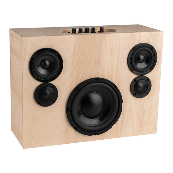
Blast Box Portable Bluetooth Speaker Kit
Thank you for purchasing the Blast Box Portable Bluetooth speaker kit. This speaker kit was
precision cut using CNC machinery for the best possible fit and finish. With a little time and
patience, your finished product will provide years of enjoyment. Please follow the following
instructions for the best possible results.
Follow this link to see the Blast Box assembly video:
Follow this link to hear a Blast Box sound test:
Suggested tools and consumables:
Drill
Screwdriver
Wood clamps (you can never have too many of these)
Sanding block and/or electric finishing sander
Wood glue
Wire stripper/crimper
Package contents:
First, empty the contents of the package and review parts to ensure everything has been included and
is in good condition. If any parts are missing or damaged please contact our customer service
department at 1-800-338-0531.
Note: Crossover components may be substituted with parts of equal or higher quality depending on
stock.
a) TPS3116D2 Class D 2.1 Bluetooth 4.0 Amplifier Board with Filter and Volume Control
b) Dayton Audio DCS165-4 6-1/2" Classic Subwoofer 4 Ohm
c) Dayton Audio DS215-PR 8" Designer Series Passive Radiator
https://youtu.be/XgAn3-kQjNQ
https://youtu.be/Ofy5A0m4xvQ
Main Components:
Rag or paper towels
Solder
Soldering iron
Hot glue gun
Polyurethane glue (Gorilla Glue)
Wrench/pliers
Advertisement

Related Manuals for Parts Express Blast Box


Summary of Contents for Parts Express Blast Box
- Page 1 Blast Box Portable Bluetooth Speaker Kit Thank you for purchasing the Blast Box Portable Bluetooth speaker kit. This speaker kit was precision cut using CNC machinery for the best possible fit and finish. With a little time and patience, your finished product will provide years of enjoyment. Please follow the following instructions for the best possible results.
- Page 2 d) Dayton Audio LBB-3 3 x 18650 Lithium Battery Charger Board/Module 12V e) 2 x Dayton Audio ND25TA-4 1" Titanium Dome Neodymium Tweeter f) 2 x Dayton Audio DSA90-8 3" Designer Series Aluminum Cone Full-Range Driver 8 Ohm Crossover Components: 2 x Dayton Audio DNR-8.0 8 Ohm 10W Precision Audio Grade Resistor 2 x Dayton Audio 1.00mH 20 AWG Air Core Inductor Crossover Coil 2 x Dayton Audio 0.10mH 20 AWG Air Core Inductor Crossover Coil...
- Page 3 Enclosure Components: l) Top Panel m) Amplifier mounting panel n) Front panel o) Back panel p) 2 x Vertical internal baffles q) 2 x Horizontal internal baffles r) 2 x Side panels s) Bottom panel Wire, Hardware, and Other Components:...
- Page 4 1 ft. Speaker Gasketing Tape 1/8” x 1/2" 1 x 3-Pack 18650 2600mAh Li-Ion Flat Top Battery 1 x Clear Acrylic Mounting Plate for Metal Panel Mount DC Jack 1 x Clear Acrylic Mounting Plate for TPS3116D2 Class D 2.1 Amp Board 5 x 0.110"...
- Page 5 10 x #8 x 3/4" Deep Thread Pan Head Screws Black 100 Pcs. 30 x #6 x 3/4" Deep Thread Pan Head Screws Black 2 x Dual Binding Post 1 Red 1 Black 1 x 2.1mm Metal Panel Mount DC Jack 10 ft.
-
Page 6: Enclosure Assembly
Enclosure Assembly: First, before gluing anything, do a dry fit of the enclosure to familiarize yourself with the parts and assembly. This will also give you a chance to ensure that all pieces have been cut properly. Next, set the enclosure parts out on a flat level surface and ensure that all pieces are free of dust and debris. - Page 7 Apply a small bead of glue to the inside of the rabbeted edges and dadoes of all joining surfaces of the horizontal inner baffles, vertical inner baffles, back, and side panels. Then set in place applying enough pressure to ensure glue is spread through each joint (some glue squeeze-out can be expected).
- Page 8 Apply a small bead of glue to the front of the amp mounting panel. Keep at least 1-1/4” away from the oval shaped opening, as shown. Also apply a small bead to each outside edge of the amp mounting panel. Then set in place as shown, applying enough pressure to ensure glue is spread through each joint (some glue squeeze-out can be expected).
- Page 9 Finally apply clamps so that even pressure is applied to all glued surfaces. With just 4 clamps, begin by using 2 clamps to apply pressure to the top and bottom panels. Next, use the other 2 clamps to hold the side panels together. Then remove the first 2 clamps from the top and bottom and move them to squeeze the front and back together near two corners.
-
Page 10: Crossover Assembly
Crossover assembly: Point-to-point wiring diagram Follow this link for a step-by-step video showing the Blast Box crossover assembly: https://youtu.be/eJSfeKH8Te8 Arrange the components as illustrated in the point-to-point wiring diagram above so the leads can be connected together as shown. Take careful note of the component type and the value of the component. -
Page 11: Final Assembly
With a hot soldering iron, apply solder to the connections between components. Heat the junctions evenly and verify that the solder flows into the connection rather than forming a "blob" on the surface (cold joint). Cut 4 lengths of red/black speaker wire approximately 12" in length and strip 1/4" - 1/2" of insulation from one end of each wire and 1/2"... - Page 12 Install dual binding posts through the 2 holes in each vertical internal baffle from inside the main enclosure using 1 of the binding post spacers for each pair. On the inside of each sub-enclosure place the ring terminals attached to the 6" red/black speaker wires to the matching red and black binding posts and secure with the supplied nuts (no binding post spacer should be used inside the sub-enclosures).
- Page 13 Prepare the TPS3116D2 Class D 2.1 Bluetooth 4.0 Amplifier Board by removing all knobs, nuts, and washers. Place the acrylic amplifier mounting plate on the amplifier with the labels on the outside and secure using the supplied nuts (no washers) and tighten using 10 mm (13/32") wrench (do not over tighten), take care not to scratch the mounting plate.
- Page 14 Place the acrylic mounting plate onto the inside of the back panel of the enclosure in the matching recess. Secure into place using 4 x #8 x 1/2" Deep Thread Pan Head Screws and 4 x nylon washers through the pre-drilled holes in the mounting plate and back panel (do not over tighten). A screwdriver can be inserted through the tweeter hole in the front panel for easy access.
- Page 15 Insert the amplifier module/mounting plate assembly into the opening in the top of the enclosure and secure in place using 8 x #6 x 3/4" Deep Thread Pan Head Screws (do not over tighten). Connect the wires from the DC IN terminal from the amplifier board to the Dayton Audio LBB- 3 3 x 18650 Lithium Battery Charger Board/Module by stabbing the stripped ends of the red and black Consolidated 22 AWG Solid Hook-Up Wire into the connectors labeled VBAT + (red wire) and VBAT - (black wire) on the end of the battery charger board.
- Page 16 You are now ready to enjoy your finished Blast Box portable Bluetooth speaker. Follow this link to see an easy wat to finish the Blast Box with a stylish flight case look: https://youtu.be/sn09e_r7Chw...
- Page 17 °, to worry about listening on axis. • For best bass response, and highest output, position the Blast Box near a wall or other rigid surface. • Lower the Sub Level and increase the Mid/High Level for maximum output capability.
- Page 18 • In situations where you will be listening primarily off-axis you can boost the Treble to improve extreme off-axis performance. • Familiarize yourself with all of the controls on the Blast Box to make adjustments on the fly, depending on the situation.
- Page 19 Blast Box Crossover Schematic:...
Need help?
Do you have a question about the Blast Box and is the answer not in the manual?
Questions and answers