Table of Contents
Advertisement
Important Note for the Installer.
A separate document (Installer level Settings) is available for programming the electronic controller should the
factory settings need to be altered. This covers temperature settings (example for UFH), Prepayment etc,.
Phone 01889 272199 to request copy.
These should not be left with the home-owner
Instructions
for installing and using HIPER HIU
Advertisement
Table of Contents

Related Manuals for Inta Hiper Xi45 INDIRECT HIU 45DHW/10HTG


Summary of Contents for Inta Hiper Xi45 INDIRECT HIU 45DHW/10HTG
- Page 1 Important Note for the Installer. A separate document (Installer level Settings) is available for programming the electronic controller should the factory settings need to be altered. This covers temperature settings (example for UFH), Prepayment etc,. Phone 01889 272199 to request copy. These should not be left with the home-owner Instructions for installing and using HIPER HIU...
-
Page 2: Section 1 - Important Information
Installation and Operating Instructions SECTIONS Hiper Xi45 INDIRECT HIU 45DHW/10HTG 1. Important information Part Code : HIPER4510 2. Description and Features 3. Dimensions and components Hiper Xi60 INDIRECT HIU 60DHW/10HTG 4. Installation and Assembly instructions, Accessories Part Code : HIPER6010 5. -
Page 3: Section 2 - Description
SECTION 2 - Description Heat Interface Units (HIU deliver heat generated from a centralised heating plant to multiple homes, apartments or flats. The method is to combine plate heat exchangers with a control valve to enable the supply of sufficient heat to provide hot water (DHWS) and room heating (HTG). The Hiper HIU has been developed to this concept with unique control and ability to optimise performance and operation. - Page 4 SECTION 2 - Description FEATURES continued Instant Hot Water Response - Instant water response is guaranteed by keeping heat (supplied by the district supply) close at hand to the HIU at all times. At regular intervals (factory set to 20 minutes), the controller opens (factory set to 2 min) the PICV to deliver a low flow of about 100 l/hr, then closes the valve again.
-
Page 5: Section 3 - Dimensions And Components
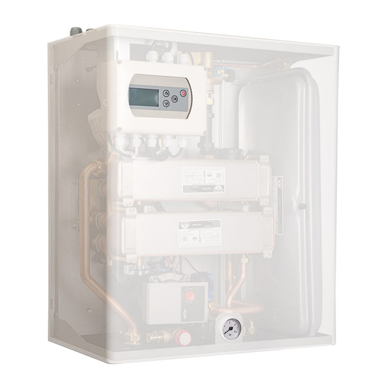
SECTION 3 - Dimensions and components SAFETY VALVE DISCHARGE PIPE CONNECTION* *optional exit hole for safety valve FILLING LOOP COLD FLOW RETURN CONNECTION DHWS Central Heating MAIN COMPONENTS 1. Strainer 2. PID Controller 3. PICV (behind the controller) 4. Heating PHE 5. -
Page 6: Section 4 - Installation And Assembly Instructions
Supplies with inadequate flow or pressure (less than 2.5 bar) Cold water mains supply should be protected from excessive high pressures. An Inta Pressure Reducing Valve is recommended and pre-set to 3 bar. To prevent water hammer a small expansion vessel is recommended – to be specified by the system designer. -
Page 7: Drain Locations
SECTION 4 - Installation and Assembly instructions CHECK LIST Checklist - Installation Checked (Initial) Choose appropriate location, Fix wall bracket level and securely. Hang the HIU into position. (Note, check if Stand Off Brackets required) Fit Primary isolation ball valves seal with gaskets provided. CHECK ALL CONNECTIONS ON THE HIU ARE TIGHT. - Page 8 SECTION 4 - Installation and Assembly instructions PRIOR TO INSTALLATION, please note. • Wall fixing bolts are to be provided by the installer and be suitable to bear the weight of the HIU and fix securely to the wall. • The position of the HIU should be in a location where pipe runs to DHW be kept to a minimum.
- Page 9 SECTION 4 - Installation and Assembly instructions OPTIONAL – FIRST FIX WITHOUT THE HIU ON SITE You will need - Part Number HIACPFFKIT. This can be provide in advance of the Hiper HIU Contents—1 pair Isolation Valves for the Primary connections to the Hiper HIU And 1 x Wall Bracket.
- Page 10 SECTION 4 - Installation and Assembly instructions 4 OPTION – FIRST FIX WITHOUT THE HIU ON SITE Stage • Now connect the secondary isolation ball valves. • Note the correct connection for flows and returns. • Connect the pipework, seal to prevent leaks when the system is pressurised.
-
Page 11: System Connections
• Once secure, hang the HIU by the Stand Off Brackets onto the two OUTER CLASPS on the wall bracket. Inta Part Number - HIAC01SOB PIPE WORK Connections and Isolation Valves Stage See Accessories for Isolation Valves! DISTRICT (PRIMARY) CONNECTIONS... - Page 12 ACCESSORIES SECTION 4 - Installation and Assembly instructions Stage Description Order as Part Code Primary First Fix Kit HIACPFFKIT Price included with HIPER HIU Can be delivered with HIU or in advance for first fix pipe work. (Use with HIPER First Fix Installation Kit Primary First Fix Kit Stand off Wall Brackets HIAC01S0BPACK...
-
Page 13: Section 5 - Electrical & Wiring Instructions
SECTION 5 - Electrical & Wiring instructions The HIU comes pre-wired for all components. A wiring box is the connection point for the installer. The installer is to provide a 230vAC 3 amp fused supply as per BS EN 7671:2008 Ensure the HIU is earthed in accordance with BS EN 7671:2008 The connections are clearly marked as : L N E... - Page 14 SECTION 5 - Electrical & Wiring instructions Connection of Pre-Payment Billing Systems For installations where the landlord of the properties has fitted a metering system that enables a scheme where the tenant pays for heat by pre-payment, the HIU is required to have the capability to shut down the supply of heat when payment agreements have not been met.
- Page 15 SECTION 5 - Electrical & Wiring instructions WIRING TO THE CONTROLLER ISOLATE THE ELECTRIC SUPPLY TO THE HIU! • The Controller front cover is fixed by 4 screws at each corner • Remove the cover and locate the terminals as pictured - spare terminals marked AUX •...
- Page 16 SECTION 6 - Commissioning HIU CHECK LIST Checklist Remarks /Notes System filled and no leaks found. Primary pipework has been flushed and is As per ICOM guide to clean. Note that the PICV must be powered shut, i.e. the controller is powered water treatment.
- Page 17 SECTION 7 - Operation - The HIU Controller The factory settings are set according to normal operating conditions and should only be changed if specified to do so! After initial start up, should the HIU be required to be turned off until the home is occupied press the ON/OFF button Switch on the Power When powered up for the first time, the controller...
-
Page 18: Section 8 - Maintenance Instructions
Central Heating side of the HIU - check the safety valve discharges by twisting the cap. Check the safety valve re-seats and seals. Satisfied all is checked, replace casing and carry out commissioning check list. System maintenance, commissioning and design is not the responsibility of INTA. 09/17 E & OE... - Page 19 SECTION 8 - Maintenance instructions Notes on the Plate Heat exchangers Plate Heat Exchangers are designed for easy access and simple removal for servicing. Four Fixing bolts and seals, all available as spares if required. Service engineers are advised to keep a stock of these spares in case during works one or more gets lost or damaged.
- Page 20 SECTION 9 - Fault codes and fault finding Explaining the HIU Controller Fault or Error diagnostics feature. FAULT CODE MESSAGE ACTION REMARKS and REFERENCES DISPLAY SYMBOL A fault or error has occurred. To identify what the fault is The warning signal is constantly flashing, press the OK button.
- Page 21 SECTION 9 - Fault codes and fault finding When carrying out any repair work on the HIU the unit must be switched off and isolated! Always isolate the power supply before opening the unit! FAULT CODE MESSAGE ACTION REMARKS and REFERENCES DISPLAY SYMBOL •...
- Page 22 SECTION 9 - Fault codes and fault finding When carrying out any repair work on the HIU the unit must be switched off and isolated! Always isolate the power supply before opening the unit! FAULT CODE MESSAGE ACTION REMARKS and REFERENCES DISPLAY SYMBOL A fault has been detected in the PICV.
-
Page 23: Troubleshooting Checklist
SECTION 9 - Installation and Assembly instructions - TROUBLE SHOOTING When carrying out any repair work on the HIU the unit must be switched off and isolated! Always isolate the power supply before opening the unit! REPORTED PROBLEM Trouble Shooting Checklist Reported problem;... - Page 24 7.0 RKC Pump 12 Flow Sensor H10015SP Honeywell Flow Sensor H10016SP Pressure switch H10017SP Inta HIU High Temperature TMV H10018SP HIU Automatic Air Vent H10019SP GASKET SEALS for Plate Heat Exchanger (4) H10020SP Fixing Bolts for 18 Plate Heat Exchanger (4)
-
Page 25: Section 11 - Technical Specifications
SECTION 11 - Technical specifications Hiper HIU Indirect models Indirect HIPER HIU Xi45 Indirect HIPER HIU Xi60 Indirect HIPER HIU Xi75 Technical Parameters Xi45 Xi60 Xi70 PRIMARY (heat supply from communal heat source) 16 bar 16 bar 16 bar MAXIMUM PRESSURE PRIMARY (heat supply from communal heat source) 90°... - Page 26 SECTION 11 - Technical specifications Main components Xi45 Xi60 Xi70 SECONDARY circulating pump Wilo Yonos Para RKA 15.7 WM Pressure Independent Control Valve (PICV) 220 – 1330 Ltrs/hr Central Heating - Zilmet Plate Heat Exchanger ZC315 ZC315 ZC315 Wras approved 1403059 Domestic Hot Water - Zilmet Plate Heat Exchanger ZC315 ZC315...
-
Page 27: Warranty
Warranty claims are subject to proof that the product has been correctly installed in accordance with the installation instructions and good working practice. Any Costs incurred by Inta that are not covered by the warranty will be invoiced to the claimant. HIU SERVICE CALL CHARGES Initial Call Out Charge, including travel and 30 minutes on site labour. - Page 28 09/17 E & OE...
Need help?
Do you have a question about the Hiper Xi45 INDIRECT HIU 45DHW/10HTG and is the answer not in the manual?
Questions and answers