Curtis ThermoPro G4 Series User Manual
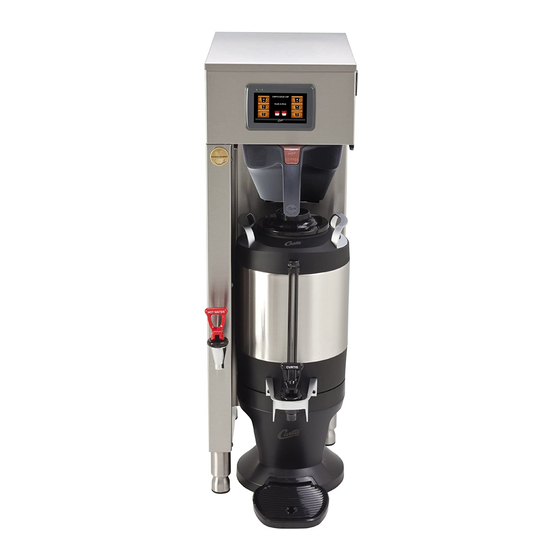
1.5 gallon coffee brewing system
Hide thumbs
Also See for ThermoPro G4 Series:
- User manual (37 pages) ,
- User manual (40 pages) ,
- User manual (36 pages)

Related Manuals for Curtis ThermoPro G4 Series


Summary of Contents for Curtis ThermoPro G4 Series
- Page 1 USER GUIDE ® G4 ThermoPro Series 1.5 Gallon Coffee Brewing System READ AND SAVE THESE INSTRUCTIONS NOTICE TO INSTALLER: Please leave this booklet with the machine.
-
Page 2: Table Of Contents
.................ES42 .......................ES52 ........................................................................................................EC1 ..............................Contact Information Wilbur Curtis Co., Inc. 6913 Acco Street | Montebello, CA 90640 US Phone: 323-837-2300 | Toll Free: 800-421-6150 Email: csrassistance@wilburcurtis.com | Web: www.wilburcurtis.com . - 4:00 . PT Email: techsupport@wilburcurtis.com 101317A... -
Page 3: Fs24
KEY FEATURES/SPECIFICATIONS/SYSTEM REQUIREMENTS FS24 Key Features ™ • Gold Cup Series – digital control module provides precise control over all aspects of brewing: time, temperature, volume plus specialty coffee needs from pre-infusion to pulse-brewing to water bypass. • Generation Four (G4) Digital Control Module – Large, 4.3” touch screen. Icon-driven interface streamlines operation. -
Page 4: Is2
INSTRUCTIONS could result in personal injury or void the warranty. • This appliance is designed for commercial use. Any service other than cleaning and preventive maintenance should be performed by an authorized Wilbur Curtis service technician. • serviceable parts inside. - Page 5 IMPORTANT SAFEGUARDS CE Requirements • This appliance must be installed in locations where it can be overseen by trained personnel. • • This appliance is not suitable for outdoor use. • • • This appliance must not be cleaned by water jet. •...
-
Page 6: Ii2
INSTALLATION INSTRUCTIONS WARNING: WARNING: Improper electrical connection may result in an electric shock hazard or damage the unit. This appliance must be properly grounded. NOTICE: DO NOT connect this appliance to a hot water supply. The water inlet valve is not rated for hot water. -
Page 7: Ii9
INSTALLATION INSTRUCTIONS Installation Leveling WARNING: Use the leveling legs to level the brewer only. Do not use them to adjust brewer height. Do not extend them higher than necessary. Position the brewer on the counter top. Level it left to right and front to back by turning the bottom of the legs. - Page 8 INSTALLATION INSTRUCTIONS Connecting the Brewer Wiring (Units That Come from Back of the Factory Without a Power Cord Attached) brewer WARNING: Do not connect the power cord to the power supply until instructed to do so. Brewers With Power Connector Mounted to the Back 11 Connect a C20 IEC power cord (not supplied) compatible with the electrical outlet installed in the Brewers With Strain Relief Mounted to the Back...
- Page 9 INSTALLATION INSTRUCTIONS Connection to an Electrical Outlet 18 If not already installed, install the appropriate type of power plug for your locality. Consult local electrical codes to determine the approved type of power plug for your region. 19 Connect the power plug to the appropriate electrical outlet.
-
Page 10: Oi11
OPERATING INSTRUCTIONS OI11 Brewing Instructions WARNING - TO AVOID SCALDING, AVOID SPLASHING. Keep body parts clear of the brewer during The G4 ThermoPro Brewer is factory preset for optimal performance. Back of brewer The brewer should be ON. Center an empty dispenser under the brew basket. -
Page 11: Ci1
CLEANING INSTRUCTIONS WARNING: HOT SURFACES - To avoid injury, allow the brewer and dispenser(s) to cool before cleaning. NOTICE - Do not use cleaning liquids, compounds or powders containing chlorine (bleach) or corrosives. USE OF THESE PRODUCTS WILL VOID THE WARRANTY. Cleaning The Brewer - Daily WARNING: DO NOT immerse the brewer in water or any other liquid. -
Page 12: Ci5
SANITIZE continued... * For 1.5 gal./5.7 L dispensers use type Z95 (Curtis PN WC-79000) For 1.0 gal./3.8 L dispensers use type Z61 (Curtis PN WC-79003) 1.0/1.5 GALLON THERMAL DISPENSER, CLEANING INSTRUCTIONS... - Page 13 CLEANING INSTRUCTIONS Cleaning the Thermal Dispenser (cont.) Disassemble the faucet - Unscrew the handle/ Style varies bonnet assembly from the top of the faucet and remove it. Inspect the seat cup for wear. Replace the Washer seat cup if it is damaged. Unscrew the cap and guard to dis-assemble.
-
Page 14: Ci9
CLEANING INSTRUCTIONS Cleaning the Airpot/Pour Pot (Daily) WARNING: DO NOT immerse the airpot/pour pot or lid assembly in water or any other liquid. Do not place the airpot/pour pot or lid in a dishwasher. Placing a airpot or pour pot in a dishwasher will void the warranty. Start by preparing a mild solution of detergent and warm water. - Page 15 Brew Buttons Control symbols - all symbols may not be present at the same time Home Undo Curtis logo Scroll Return to previous left/right Manual Programming Mode The ACCESS CODE screen will appear. The The MAIN MENU screen contains a series of sub- default pass code is 1 2 3 4.
- Page 16 PROGRAMMING GUIDE Manual Programming Mode (cont.) Recipes Control Settings Brew Settings Settings Summary Model Select Exit Temperature Settings Coffee Combo Warmer Settings Quality Timer Energy Savings Gourmet Std Satellite LED Color Light Roast Gemini Sounds By Volume/Time Dark Roast Gemini IF Diagnostics One Batch Pre/Pulse...
- Page 17 PROGRAMMING GUIDE Control Settings Menu Temperature - Warmer Settings (some models) • Auto-Off (G4GEMS/G4GEMT series) - adjusts the time that elapses before the dispenser warmer • Auto-Off (G4GEMSIF/G4GEMTIF series) - adjusts the time that elapses before the dispenser • Power Setting (All G4 Gemini series) - ®...
- Page 18 PROGRAMMING GUIDE Control Settings Menu (cont.) Passwords • Programming Password - default is 1234. • Brew Password - turns the brew access password feature on and off and is used to create the pressed. The correct access code must be entered before brewing will proceed. •...
- Page 19 PROGRAMMING GUIDE Brew Settings Menu (cont.) Pulse Brew - reaches brewing temperature. Setting Description Toward the beginning of brew cycle: 4 cycles of 10 seconds on and 10 seconds off, then on until end of brew cycle. Starts towards ends of brew cycle. 4 cycles of 10 seconds off and 4 cycles of 10 seconds on. Ends when brew cycle ends.
- Page 20 PROGRAMMING GUIDE Automatic Programming - USB IMPORTANT: starting the following process. Uploading the Software to the Flash Drive as desired. Downloading the Software to the Brewer from the Flash Drive a second. USB File Transfer FILE TRANSFER Upload Download No Action to USB from USB Settings/recipes...
- Page 21 ROUGH-IN DRAWINGS RD30 G4TP2S - Single Coffee Brewer 20.75 in [52.7 cm] 35.14 in [89.2 cm] 24.00 in [60.0 cm] 8.38 in 11.07 in [21.0 cm] [28.1 cm] 4.00 in [10.2 cm] G4TP2T - Twin Coffee Brewer 20.75 in 35.42 in [52.7 cm] [90.0 cm] 24.00 in...
- Page 22 ILLUSTRATED PARTS LIST IP42 G4TP2S - Main Chassis - Exploded View * Water tanks assemblies - See section IP43 for single voltage models - See section IP44 for dual voltage models G4TP2, ILLUSTRATED PARTS/RECOMMENDED PARTS 051618C...
- Page 23 ILLUSTRATED PARTS LIST IP42 G4TP2S - Main Chassis - Parts List ITEM # PART # DESCRIPTION ITEM # PART # DESCRIPTION WC-5350 TUBE, 1/2 ID x 1/8W SILICONE GEN USE SWITCH, TOGGLE NON-LIT DPST 25A WC-103 125/250VAC RESISTIVE WC-61509 COVER, TOP TP2S VALVE, INLET 2 GPM 120V 10W GEN USE WC-847 1 VALVE, DUMP RIGHT 120V 12W W/INTERNAL...
- Page 24 ILLUSTRATED PARTS/RECOMMENDED PARTS IP42 G4TP2T - Main Chassis - Exploded View * Water tank assembly, see section IP45 G4TP2, ILLUSTRATED PARTS/RECOMMENDED PARTS 051618C...
- Page 25 ILLUSTRATED PARTS LIST IP42 G4TP2T - Main Chassis - Parts List ITEM # PART # DESCRIPTION ITEM # PART # DESCRIPTION VALVE, DUMP RIGHT 120V 12W W/INTERNAL WC-29044-101 SLEEVE, OVERFLOW WC-820WDR 1 RESISTOR & DIODE CORD, 4mm² 90ºC 49A 450/750V 6 FT LG W/ WC-1250 2 VALVE, BREW DUMP RIGHT 240V 12W GEM12D/ FERRULES ONE END (NOT SHOWN)
- Page 26 ILLUSTRATED PARTS LIST IP43 WC-62032 - Tank Assembly WC-62032 - Tank Assembly - Parts List ITEM # PART # DESCRIPTION ITEM # PART # DESCRIPTION WC-62032 TANK, COMPLETE TP2S ULTEM FITTNGS THERMOSTAT, HI LIMIT HEATER CONTROL DPST WC-522* 277V 40A WC-5853-102 COVER, TOP HEATING TANK GEN USE WC-43055*...
- Page 27 ILLUSTRATED PARTS LIST IP44 WC-62031 - Tank Assembly WC-62031 - Tank Assembly - Parts List ITEM # PART # DESCRIPTION ITEM # PART # DESCRIPTION WC-62031 TANK, COMPLETE TP2S (2) 1600W/120V THERMOSTAT, HI LIMIT HEATER CONTROL WC-522 DPST 277V 40A WC-5853-102 COVER, TOP HEATING TANK GEN USE WC-43055...
- Page 28 ILLUSTRATED PARTS/RECOMMENDED PARTS IP45 WC-62030 - Tank Assembly WC-62030 - Tank Assembly - Parts List ITEM # PART # DESCRIPTION ITEM # PART # DESCRIPTION WC-62030 TANK, COMPLETE TP2T ULTEM FITTNGS WC-4382* GUARD, SHOCK HTNG ELMNT DOUBLE WC-37008 KIT, TANK LID ROUND (INCLUDES GASKET) THERMOSTAT, HI LIMIT HEATER CONTROL DPST WC-522* 277V 40A...
-
Page 29: Es49
ELECTRICAL SCHEMATICS ES49 SINGLE, DOMESTIC, 220 VOLT GTPSG4-10, ELECTRICAL SCHEMATIC 062519C... -
Page 30: Es41
ELECTRICAL SCHEMATICS ES41 G4GEMS63x, G4TP[X]1S63x, G4TP[X]2S63x GTPSG4-63, ELECTRICAL SCHEMATIC 033120C... - Page 31 ELECTRICAL SCHEMATICS ES50 SINGLE, 220-240 VOLT, DUAL ELEMENT GTPSG4-30, ELECTRICAL SCHEMATIC 081319D...
-
Page 32: Es42
ELECTRICAL SCHEMATICS ES42 G4GEMT10x, G4TP[X]1T10x, G4TP[X]2T10x GTPTG4-10, ELECTRICAL SCHEMATIC 033120C... -
Page 33: Es52
ELECTRICAL SCHEMATICS ES52 G4GEMT30x, G4TP[X]1T30x, G4TP[X]2T30x GTPTG4-30, ELECTRICAL SCHEMATIC 033120D... - Page 34 TROUBLESHOOTING GUIDE WARNING: Electric Shock Hazard - Scald and Burn Hazard - IMPORTANT: always check all Valve Test Procedure Troubleshooting Guidelines • • • • Valve Test Procedure in either direction Water Not Hot Enough replace the temperature sensor Water Heats More Slowly Than Usual During Brewing...
- Page 35 TROUBLESHOOTING GUIDE No Power - Display Not Lit Water Tank Does Not Fill Brewer Does Not Start When Brew Button is Pressed Brewing Brewing Sensor Error Message...
- Page 36 TROUBLESHOOTING GUIDE Water Tank Does Not Fill IMPORTANT: Coffee/Tea Too Strong Dispenser Not Filled To Normal Level During Brewing Dispenser Not Filled To Normal Level During Brewing sure that the spray head is correctly aligned and that the tubing is routed properly to allow for maximum water All Of The Time...
- Page 37 TROUBLESHOOTING GUIDE No Water/Tea Flows From Brewer During Brewing Water Tank Does Not Fill Low Water Flow Warning Water Level Error Message Water Level Error Message “Internal Error 1” Message on Display “Internal Error 2” Message on Display PROGRAMMING GUIDE...
- Page 38 TROUBLESHOOTING GUIDE Water Does Not Heat At All Check to see if the water level in the tank is in contact with the water level probe. If not, see Tank Does Not Fill. • The water will not heat unless it is in contact with the probe. If the water heats, but is not hot enough, see Water Not Hot Enough.
- Page 39 Display view varies Using the Diagnostics with model The MAIN MENU Control Settings. Diagnostics Auto Test to test all circuits. If a button is highlighted green the Curtis logo DIAGNOSTICS Left Auto Test Right Dump Vavle Inlet Valve Dump Vavle Cone Lock...
-
Page 40: Ec1
ERROR CODES Warning Messages - Allows Brewer to Continue Brewing MESSAGE DISPLAY WARNING DESCRIPTION CAUSE Brew count “Gallons Since Reset” exceeds programmed Maintenance Required Maintenance Required preventative maintenance period. If the Inlet valve remains on longer than XX seconds (during the brew cycle only) and repeats TWICE during that brew cycle. - Page 41 Return Merchandise Authorization (RMA): All returned equipment must be properly re-packaged in the original carton and received by Curtis within 45 days following the issuance of a RMA. NO UNITS OR PARTS WILL BE ACCEPTED WITHOUT A RETURN MERCHANDISE AUTHORIZATION (RMA).
Need help?
Do you have a question about the ThermoPro G4 Series and is the answer not in the manual?
Questions and answers