
Related Manuals for Texas Instruments DLP LightCrafter 6500


Summary of Contents for Texas Instruments DLP LightCrafter 6500
- Page 1 LightCrafter™ 6500 and 9000 Evaluation ® Module (EVM) User's Guide User's Guide Literature Number: DLPU028C October 2014 – Revised November 2016...
-
Page 2: Table Of Contents
............................Preface ..............DLP LightCrafter 6500 and 9000 Module Overview ........................Welcome ........What is in the DLP LightCrafter 6500 and 9000 Evaluation Module (EVM)? ........................ EVM Boards ..................Other Items Needed for Operation ..................DLP LightCrafter 6500 Connections ............ - Page 3 Power Supply Requirements ................... External Power Supply Requirements ..........................Safety ........................Revision C History ........................Revision B History ........................Revision A History DLPU028C – October 2014 – Revised November 2016 Contents Submit Documentation Feedback Copyright © 2014–2016, Texas Instruments Incorporated...
- Page 4 DLP LightCrafter 9000 EVM Block Diagram ................ 1-5. DLP LightCrafter 6500 Connectors (Top View) .............. 1-6. DLP LightCrafter 6500 Trigger Voltage Level Selectors ................ 1-7. DLP LightCrafter 9000 Connectors (Top View) .............. 1-8. DLP LightCrafter 9000 Trigger Voltage Level Selectors ......................
- Page 5 C Port 2 Connector Pins .................. 4-7. JTAG Boundary Scan Connector Pins ..................4-8. GPIO and PWM Connector Pins ..................... 4-9. Power Connector Pins DLPU028C – October 2014 – Revised November 2016 List of Tables Submit Documentation Feedback Copyright © 2014–2016, Texas Instruments Incorporated...
-
Page 6: Preface
DLP reference designs to enable faster development cycles requiring higher resolution for video and intelligent pattern display applications. This guide is an introductory document for the DLP LightCrafter 6500 and 9000 that provides an overview of the system and its software. Other documents provide more in-depth information of the hardware and software features of the components of the DLP LightCrafter 6500 and 9000. -
Page 7: Dlp Lightcrafter 9000 Evaluation Module
User's Guide: DLPC900 Programmer's Guide, DLPU018 If You Need Assistance Refer to the DLP Products and MEMS TI E2E Community support forums. DLPU028C – October 2014 – Revised November 2016 Read This First Submit Documentation Feedback Copyright © 2014–2016, Texas Instruments Incorporated... -
Page 8: Dlp Lightcrafter 6500 And 9000 Module Overview
DLPU028C – October 2014 – Revised November 2016 DLP LightCrafter 6500 and 9000 Module Overview Welcome The DLP LightCrafter 6500 and 9000 modules allow evaluation of TI’s DLP6500 and DLP9000 platforms. This technology brings together a set of components providing an efficient and compelling system solution for: •... -
Page 9: What Is In The Dlp Lightcrafter 6500 And 9000 Evaluation Module (Evm)
What is in the DLP LightCrafter 6500 and 9000 Evaluation Module (EVM)? www.ti.com What is in the DLP LightCrafter 6500 and 9000 Evaluation Module (EVM)? The DLP LightCrafter 6500 and 9000 module consist of two subsystems: • DLPC900 Board – Includes the DLPC900, digital receiver, flash, power management circuits, and supporting digital logic. -
Page 10: Evm Boards
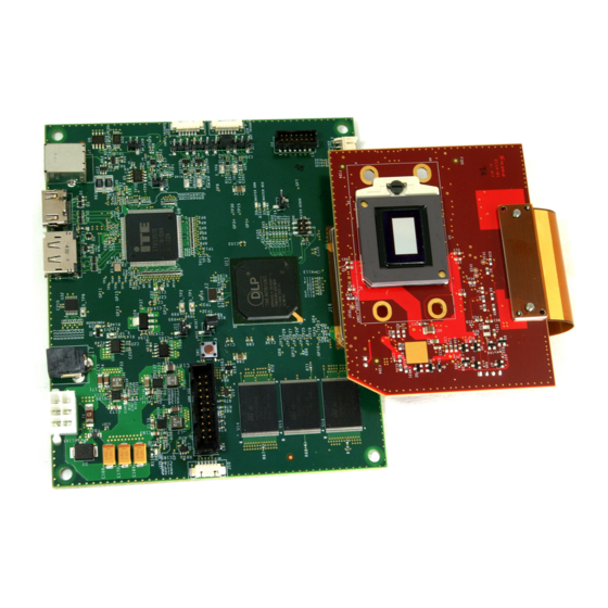
EVM Boards www.ti.com EVM Boards The DLP LightCrafter 6500 and 9000 EVMs contain the electronics to drive the DLP6500 and the DLP9000 DMDs. The EVMs offer several interface options for USB, I C, trigger inputs and outputs, video input through HDMI and Display Port connectors. -
Page 11: Dlp Lightcrafter 9000 Evm Block Diagram
3.3V 1.8V LDO TPS54620RGYR TPS54320RHLR TPS54620RGYR TLV117118DCY Figure 1-4. DLP LightCrafter 9000 EVM Block Diagram The DLP LightCrafter 6500 major components are: • DLP6500 0.65-inch 1080p DMD • DLPC900 Controller • 48-MB parallel FLASH contains DLPC900 firmware and pattern images •... -
Page 12: Other Items Needed For Operation
Other Items Needed for Operation The DLP LightCrafter 6500 and 9000 EVMs are flexible, ready-to-use evaluation modules (EVM). However, the DLP LightCrafter 6500 and 9000 EVMs do not ship with optics, illumination source, cables, power supplies, or additional hardware components. -
Page 13: Dlp Lightcrafter 6500 Connections
Note that neither cables nor the power supply is included with the module. Figure 1-5. DLP LightCrafter 6500 Connectors (Top View) • SW1 – Reset switch. When pressed, resets the controller. - Page 14 – Pin 6 is Green LED Enable output. – Pin 7 is Blue LED Enable output. – Pin 8 is RED PWM output. DLP LightCrafter 6500 and 9000 Module Overview DLPU028C – October 2014 – Revised November 2016 Submit Documentation Feedback...
-
Page 15: Dlp Lightcrafter 6500 Led Enable And Pwm Outputs
POSENSE goes high. GPIO_CONFIG: 0x8 0x3 1.5.1 DLP LightCrafter 6500 LED Enable and PWM Outputs The LED enables on J23 are low-current 3.3-V outputs and should not be used to drive LEDs directly. The enables should be used as a control to enable a regulator that provides the necessary current to the LEDs. -
Page 16: Dlp Lightcrafter 6500 Trigger Input And Output Voltage Selectors
DLP LightCrafter 6500 Connections www.ti.com 1.5.2 DLP LightCrafter 6500 Trigger Input and Output Voltage Selectors The trigger inputs on J20 are inputs from external devices to control the pattern sequence. While trigger input 2 is high, trigger input 1 will advance the pattern sequence to the next pattern in the sequence on every pulse. -
Page 17: Dlp Lightcrafter 9000 Connections
– Pin 1 = 3.3 V – Pin 2 = TX out – Pin 6 = Ground DLPU028C – October 2014 – Revised November 2016 DLP LightCrafter 6500 and 9000 Module Overview Submit Documentation Feedback Copyright © 2014–2016, Texas Instruments Incorporated... - Page 18 – Jump across pins 2 to 3 for 1.8 V • J23 – Trigger input connector. Trigger input 1 and 2 for triggering the DLPC900 with external devices. DLP LightCrafter 6500 and 9000 Module Overview DLPU028C – October 2014 – Revised November 2016 Submit Documentation Feedback...
- Page 19 GPIO output will go high in approximately 800 ms from the time POSENSE goes high. GPIO_CONFIG: 0x8 0x3 DLPU028C – October 2014 – Revised November 2016 DLP LightCrafter 6500 and 9000 Module Overview Submit Documentation Feedback Copyright © 2014–2016, Texas Instruments Incorporated...
-
Page 20: Dlp Lightcrafter 9000 Led Enable And Pwm Outputs
Pin 1 Pin 3 Pin 2 Pin 1 Figure 1-8. DLP LightCrafter 9000 Trigger Voltage Level Selectors DLP LightCrafter 6500 and 9000 Module Overview DLPU028C – October 2014 – Revised November 2016 Submit Documentation Feedback Copyright © 2014–2016, Texas Instruments Incorporated... -
Page 21: Dlp Lightcrafter 6500 And Dlp Lightcrafter 9000 Evm Flex Cable
DLP LightCrafter 6500 and DLP LightCrafter 9000 EVM Flex Cable www.ti.com DLP LightCrafter 6500 and DLP LightCrafter 9000 EVM Flex Cable Electrical malfunctions can occur by stressing the flex cable(s) connecting the DMD circuit board to the DLPC900 controller circuit board. Stressing the flex cable can be caused by: •... -
Page 22: Quick Start
Power-up the DLP LightCrafter 6500 or 9000 The DLP LightCrafter 6500 and 9000 are ready to use, out of the box. Steps 1 through 6 show how to power, display an image, and connect the EVM to a PC. -
Page 23: Pattern Mode Panel
8. Click the Start button to run the pattern sequence. 9. Click the Stop button to stop the pattern sequence. Figure 2-1. Pattern Mode Panel DLPU028C – October 2014 – Revised November 2016 Quick Start Submit Documentation Feedback Copyright © 2014–2016, Texas Instruments Incorporated... -
Page 24: Simple Three Pattern Sequence
Creating A Simple Pattern Sequence www.ti.com Figure 2-2. Simple Three Pattern Sequence Quick Start DLPU028C – October 2014 – Revised November 2016 Submit Documentation Feedback Copyright © 2014–2016, Texas Instruments Incorporated... -
Page 25: Operating The Dlp Lightcrafter 6500 And 9000
DLPU028C – October 2014 – Revised November 2016 Operating the DLP LightCrafter 6500 and 9000 This chapter introduces the PC software provided with the DLP LightCrafter 6500 and 9000. DLP LightCrafter 6500 and 9000 Control Software The DLPC900REF-SW bundle includes a QT-based GUI application to control the modules through the USB interface. -
Page 26: Pc Software
Figure 3-1. DLP LightCrafter 6500/9000 GUI System Common Controls The DLP LightCrafter 6500 & 9000 GUI communicates with the DLPC900 using USB 1.1. The DLPC900 enumerates as a USB device with HID Support. The PC polls all the HID peripherals and, once the PC detects the DLPC900, the Connected radio-button changes to green. -
Page 27: Chipset Type
3.3.2 Chipset Type The GUI will query the EVM to determine if it is connected to a DLP LightCrafter 6500 or 9000. The indicators in the Chipset Type group box will be updated to show which of the two EVMs is connected. -
Page 28: System Settings
Click the System Settings button at the top of the GUI to display the System Settings panel shown in Figure 3-2. Figure 3-2. System Settings Panel Operating the DLP LightCrafter 6500 and 9000 DLPU028C – October 2014 – Revised November 2016 Submit Documentation Feedback Copyright © 2014–2016, Texas Instruments Incorporated... -
Page 29: Video Mode
DLPC900 sequencer to control them. The LED current regulates the brightness of the LEDs. Setting the Invert PWM causes the LED urrents to have an opposite effect on the LEDs as the current is changed. Note, the DLP LightCrafter 6500 and 9000 do not come with LEDs or optical engines of any kind. -
Page 30: Video Support
Input Port Data Swap – Depending on the routing of the parallel RGB data lines, it may be necessary to swap the order of the color channels. Both the DLP LightCrafter 6500 and 9000 require ABC->BAC setting. ABC corresponded to RGB; therefore, the settings mentioned previously means that channels RG are swapped. -
Page 31: Pattern Modes
Using USB is preferred for its higher upload speed. Figure 3-4. Pattern Mode Design Panel DLPU028C – October 2014 – Revised November 2016 Operating the DLP LightCrafter 6500 and 9000 Submit Documentation Feedback Copyright © 2014–2016, Texas Instruments Incorporated... -
Page 32: Menu Bar
The bitmap images must be located in the same directory as the text file. See Figure 3-7 after the images have been added. Operating the DLP LightCrafter 6500 and 9000 DLPU028C – October 2014 – Revised November 2016 Submit Documentation Feedback Copyright © 2014–2016, Texas Instruments Incorporated... -
Page 33: Add From List
Pattern Modes www.ti.com Figure 3-6. Add From List Figure 3-7. Pattern Sequence DLPU028C – October 2014 – Revised November 2016 Operating the DLP LightCrafter 6500 and 9000 Submit Documentation Feedback Copyright © 2014–2016, Texas Instruments Incorporated... -
Page 34: Three Pattern Sequence
12. To stop the pattern sequence, click the Stop button. To restart the pattern sequence click the Start button. The pattern sequence will start from the beginning whenever the pattern sequence is stopped using the Stop button. Operating the DLP LightCrafter 6500 and 9000 DLPU028C – October 2014 – Revised November 2016 Submit Documentation Feedback... -
Page 35: Creating A Pattern Sequence In Pre-Stored Pattern Mode
While the video source is stable and locked, the status box for Locked to External Source will remain checked. DLPU028C – October 2014 – Revised November 2016 Operating the DLP LightCrafter 6500 and 9000 Submit Documentation Feedback Copyright © 2014–2016, Texas Instruments Incorporated... - Page 36 16. Click the Stop button to end this example. Figure 3-9 after all settings have been applied. Operating the DLP LightCrafter 6500 and 9000 DLPU028C – October 2014 – Revised November 2016 Submit Documentation Feedback Copyright © 2014–2016, Texas Instruments Incorporated...
-
Page 37: Video Pattern Mode
Pattern Modes www.ti.com Figure 3-9. Video Pattern Mode DLPU028C – October 2014 – Revised November 2016 Operating the DLP LightCrafter 6500 and 9000 Submit Documentation Feedback Copyright © 2014–2016, Texas Instruments Incorporated... -
Page 38: Creating A Pattern Sequence With Dmd Block Load
The DMD Idle Mode command is located in Section 3.6.6 within the Pattern Mode panel. Operating the DLP LightCrafter 6500 and 9000 DLPU028C – October 2014 – Revised November 2016 Submit Documentation Feedback Copyright © 2014–2016, Texas Instruments Incorporated... -
Page 39: Dmd Block Load Pattern Sequence
Pattern Modes www.ti.com Figure 3-10. DMD Block Load Pattern Sequence DLPU028C – October 2014 – Revised November 2016 Operating the DLP LightCrafter 6500 and 9000 Submit Documentation Feedback Copyright © 2014–2016, Texas Instruments Incorporated... -
Page 40: Pattern Settings
The DMD Idle Mode provides a 50/50 duty cycle across the entire DMD mirror array, where the mirrors are flipped between the on and off states to optimize the performance of the mirrors. Figure 3-11. Pattern Settings Panel Operating the DLP LightCrafter 6500 and 9000 DLPU028C – October 2014 – Revised November 2016 Submit Documentation Feedback... -
Page 41: Batch Files
Programmers Guide for the batch file commands in Appendix B for a complete list of commands that can be used within a batch file. DLPU028C – October 2014 – Revised November 2016 Operating the DLP LightCrafter 6500 and 9000 Submit Documentation Feedback Copyright © 2014–2016, Texas Instruments Incorporated... -
Page 42: Creating A Batch File
Within the Batch File panel, each command can also be deleted or a delay can be inserted between commands. Operating the DLP LightCrafter 6500 and 9000 DLPU028C – October 2014 – Revised November 2016 Submit Documentation Feedback... -
Page 43: Batch File Example
Once all three commands are added, save the file as a text file and use a name to describe what the batch file does. DLPU028C – October 2014 – Revised November 2016 Operating the DLP LightCrafter 6500 and 9000 Submit Documentation Feedback Copyright © 2014–2016, Texas Instruments Incorporated... - Page 44 NOTE: The user must exercise caution when selecting the correct firmware file. Install DLP LightCrafter 6500 or 9000 GUI version 2.0 or later. Operating or updating the firmware on the DLP LightCrafter 6500 or 9000 using GUI version 1.1 (or earlier) will render the EVM inoperable.
-
Page 45: Peripherals
The Pulse Width Modulate Control group box allows a user to configure any of the four available PWM outputs. NOTE: GPIO_00 – GPIO_03 are shared with the four PWM outputs. DLPU028C – October 2014 – Revised November 2016 Operating the DLP LightCrafter 6500 and 9000 Submit Documentation Feedback Copyright © 2014–2016, Texas Instruments Incorporated... -
Page 46: Firmware
24 1-bit images, 3 8-bit images, or a combination of images of various bit-depths which add up to a 24-bit composite image. Operating the DLP LightCrafter 6500 and 9000 DLPU028C – October 2014 – Revised November 2016 Submit Documentation Feedback Copyright ©... - Page 47 Pre-Stored Pattern Mode. The remainder of this topic will apply only to Pre-Stored Pattern Mode. The DLP LightCrafter 6500 and 9000 EVMs are pre-loaded with a pattern sequence that is displayed when power is applied to the EVMs. Since the GUI does not know the images that are stored in flash memory, it is advisable to delete all images from flash before storing new ones.
- Page 48 Pattern LUT Definition that is sent to the EVM, and then using the Batch File method to upload the Pattern LUT Definition and Configuration settings to the EVM. Operating the DLP LightCrafter 6500 and 9000 DLPU028C – October 2014 – Revised November 2016 Submit Documentation Feedback...
- Page 49 Pattern LUT Definition and Configuration batch files that select different images and bit positions from the images stored in the firmware. DLPU028C – October 2014 – Revised November 2016 Operating the DLP LightCrafter 6500 and 9000 Submit Documentation Feedback Copyright © 2014–2016, Texas Instruments Incorporated...
-
Page 50: Jtag Flash Programming
4. J2-8 → TDO1 (OUTPUT) 5. J2-9 → TDI (INPUT) 6. J2-10 → TMS1 (OUTPUT) 7. J2-11 → TRSTZ (OUTPUT) Operating the DLP LightCrafter 6500 and 9000 DLPU028C – October 2014 – Revised November 2016 Submit Documentation Feedback Copyright © 2014–2016, Texas Instruments Incorporated... -
Page 51: Altera Fpga Programming
Choose the driver found in the CDM WHQL Certified zip folder and allow driver installation to complete. Install a jumper at J9 on the DLP LightCrafter 6500 EVM or J10 on the DLP LightCrafter 9000 EVM. Connect the JTAG signals at J10 on the DLP LightCrafter 6500 EVM or J11 on the DLP LightCrafter 9000... -
Page 52: Connectors
Connectors This chapter describes the connector pins of the DLP LightCrafter 6500 and 9000 Module. Input Trigger Connectors The input trigger connector J20 on the DLP LightCrafter 6500 and J23 on the DLP LightCrafter 9000 pins are listed in Table 4-1. -
Page 53: Dlpc900 Uart
DLPC900 I C Port 1 NOTE: On the DLP LightCrafter 6500, the silk screen labels J14 and J15 are swapped on one board lot. Labels for I2C_2 and I2C_1 on the boards are correct. I2C_1 is J14 and I2C_2 is J15. -
Page 54: Dlpc900 I 2 C Port 2
DLPC900 I C Port 2 NOTE: On the DLP LightCrafter 6500, the silk screen labels J14 and J15 are swapped on one board lot. Labels for I2C_2 and I2C_1 on the boards are correct. I2C_1 is J14 and I2C_2 is J15. -
Page 55: Power
Ground Ground Ground Ground Ground Power The power socket J17 on the DLP LightCrafter 6500 and J20 on the DLP LightCrafter 9000 pins are shown in Table 4-9. Two matching connector part numbers are: • Switchcraft part number: 760 •... -
Page 56: Power Supply Requirements
Chapter 5 DLPU028C – October 2014 – Revised November 2016 Power Supply Requirements External Power Supply Requirements The DLP LightCrafter 6500 and 9000 do not include a power supply. The external power supply requirements are: • Nominal voltage: 12-V DC -5%/+10% •... -
Page 57: Safety
Page ............. • Added bullets "Automated optical inspection" and "Solder paste inspection" ......... • Added section "DLP LightCrafter 6500 and DLP LightCrafter 9000 EVM Flex Cable" ................• Clarified J7(LCr 6500) and J8 (LCr 9000) connection ................. • Changed figure "DLP LightCrafter 6500/9000 GUI"... -
Page 58: Revision A History
Added it is capable to add more than 400 patterns to flash memory........... • Added instructions to remove jumpers after JTAG programming is complete. Revision History DLPU028C – October 2014 – Revised November 2016 Submit Documentation Feedback Copyright © 2014–2016, Texas Instruments Incorporated... - Page 59 IMPORTANT NOTICE Texas Instruments Incorporated and its subsidiaries (TI) reserve the right to make corrections, enhancements, improvements and other changes to its semiconductor products and services per JESD46, latest issue, and to discontinue any product or service per JESD48, latest issue.
- Page 60 Mouser Electronics Authorized Distributor Click to View Pricing, Inventory, Delivery & Lifecycle Information: Texas Instruments DLPLCR9000EVM DLPLCR6500EVM...
Need help?
Do you have a question about the DLP LightCrafter 6500 and is the answer not in the manual?
Questions and answers