Advertisement
Quick Links
If you are reading this, most probably, you are
about to build Erica Synths DIY BASSLINE module.
The module is 45mm deep, skiff friendly, has solid
mechanical construction and doesn't require wiring.
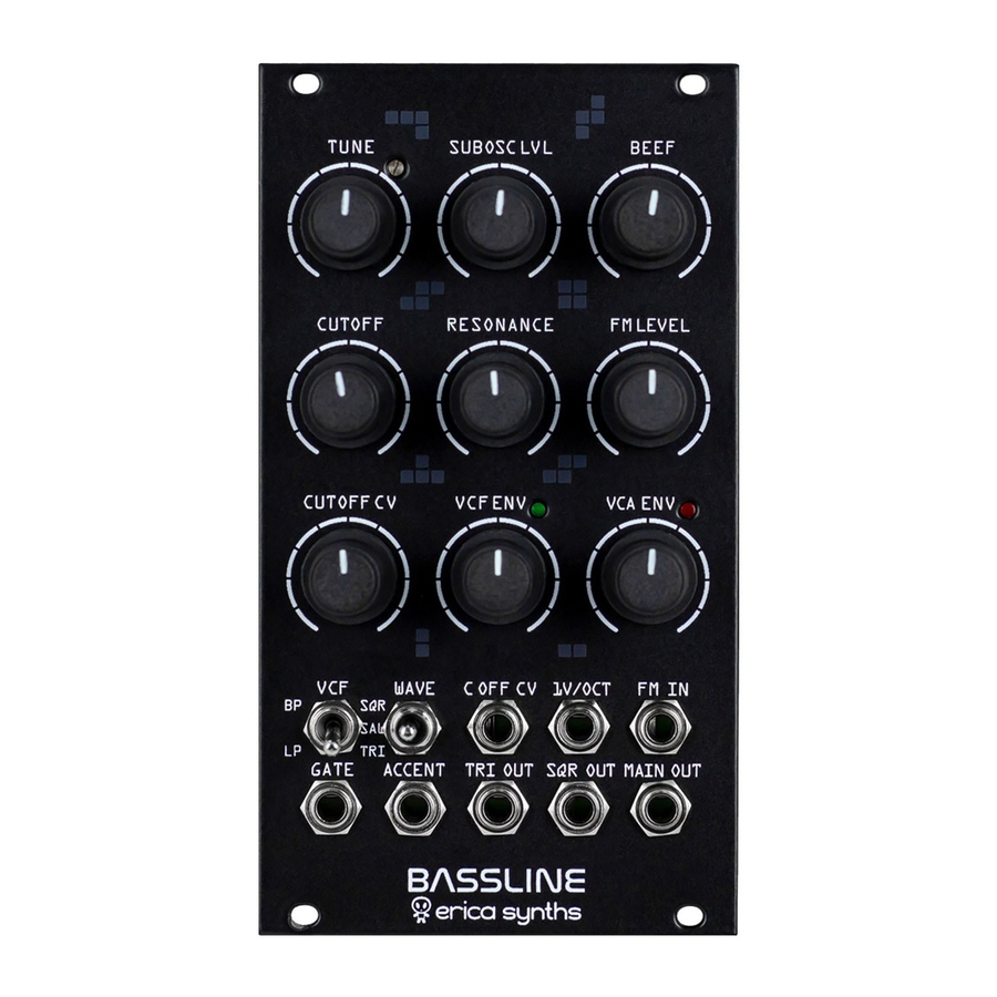
Erica Synths Bassline is full analogue synth
voice module for ultimate acid basslines. It features
highly stable AS3340-based VCO with three
waveforms, a filter inspired by Erica Synths Acidbox
and unique feature – transistor-based suboscillator.
Accent provides more expression to the bassline, by
adding volume and opening the VCF slightly.
The Bassline kit comes in three versions:
1) Set of 2 PCBs + rare ICs + mechanical parts (PCB
connectors and spacer),
2) Set of 2 PCBs + rare ICs + mechanical parts (PCB
connectors and spacer)+ panel,
3) Full kit.
FEATURES:
• Full analogue circuit
• Great 1V/oct tracking
• Simultaneous Triangle, Square and Master
outputs
• Accent
• Transistor-based suboscillator
• VCF and VCA decay envelopes
• LP/BP VCF
• External VCO FM and VCF cutoff CV inputs
SPECIFICATIONS:
• Pitch range
• Audio output amplitude
• CV amplitude (full span)
• Panel width
• Module depth
• Power consumption
GUIDE TO ASSEMBLY OF ERICA SYNTHS BASSLINE MODULE
C0-C8
10Vptp
-5V - +5V
16HP
45mm
80mA @+12V,
40mA@-12V
1
4
7
10
15
1
Set the initial tune of the VCO
Add some power to the sound! This is octave down transistor-based
2
suboscillaotr level control and effects Main output only
3
Set desired overdrive level! It effects Main output only
4
Big knobs are for VCF cutoff manual control!
Adjust the VCF resonance! The filter is the same as on DIY Polivoks
5
VCF, and it's capable of extreme resonance sweeps.
This is an external FM level attenuator. You can also do some self-
6
modulation by patching TRI OUT in to FM IN and increasing FM level.
Adjust VCF cutoff CV level! If nothing is patched in C OFF CV input, it
7
adjusts VCF envelope impact on the cutoff
8
Adjust the VCF cutoff envelope decay time
Adjust the VCA envelope decay time. Full CW setting will open
9
the VCA even the gate is not present
10
Select the VCF mode
11
Select the VCO waveform that is sent to the master output
12
This is an external CV input to control the VCF cutoff
13
This is the VCO 1V/oct input. It tracks well over 9 octaves
14
This is the VCO FM input
This is the Gate input. It accepts gate from any sequencer and
15
sends it to the VCF and VCA envelopes simultaneously
This is the Accent input. +10V CV will increase the volume and
16
open the VCF slightly to an expression to the bassline
These are additional VCO outputs, and they are not affected by VCF
17 18
and VCA. You can use them as additional sound sources that are in
tune with your bassline
19
This is the main output of the module
2
5
8
11
12
13
16
17
18
3
6
9
14
19
Advertisement

Related Manuals for Erica Synths BASSLINE


Summary of Contents for Erica Synths BASSLINE
- Page 1 VCF and VCA envelopes simultaneously This is the Accent input. +10V CV will increase the volume and open the VCF slightly to an expression to the bassline These are additional VCO outputs, and they are not affected by VCF 17 18 and VCA.
- Page 2 GUIDE TO ASSEMBLY OF ERICA SYNTHS BASSLINE ASSEMBLY Take precautions with regard to electrostatic discharge (ESD) safety. Handling components should be done in electrostatically safe environment. Use personal and workplace grounding. Any discharge (even a minor one) from body to a component may permanently damage it.
- Page 3 GUIDE TO ASSEMBLY OF ERICA SYNTHS BASSLINE Solder potentiometers, switches, jacks and transistors (pay close attention on transistor denominations and orientation) on the Controls board and vertically placed resistors on the Main board! Solder transistors and K140UD12 opamps on the Main board! Pay close attention on orientation of transistors and opamps! Solder electrolytic capacitors.
- Page 4 GUIDE TO ASSEMBLY OF ERICA SYNTHS BASSLINE Solder trimpots and pinheader for a jumper. The jumper Turn the Main board around and solder male configures cutoff CV potentiometer. If placed on top connectors! Make sure, they are 90 against pins, the CV potentiometer works as attenuverter the PCB! Place female connectors on the male allowing inverted envelopes, if on bottom pins –...
- Page 5 GUIDE TO ASSEMBLY OF ERICA SYNTHS BASSLINE Use M3x6 screw to fix the 11mm spacer on Insert LEDs, but do not solder them, yet! the Controls board Connect the Controls PCB and the Main PCB and use Now place the front panel and make sure LEDs fit in another M3x6 screw to fix them.
- Page 6 GUIDE TO ASSEMBLY OF ERICA SYNTHS BASSLINE CALIBRATION 1) Connect the VCO to the PSU. Let it "heat up" for ~10mins. 2) Turn the VCA Envelope potentiometer all way CW, TUNE potentiometer to 12:00 and all other potentiometers all way CCW! Set waveform select switch to the SAW, VCF mode switch - to LP! Install the VCF configuration jumper to Attenuator position (lowest).
Need help?
Do you have a question about the BASSLINE and is the answer not in the manual?
Questions and answers