Table of Contents
Advertisement
Quick Links
Advertisement
Table of Contents

Related Manuals for ABB Terra 54 Series


Summary of Contents for ABB Terra 54 Series
- Page 1 — MANUA L Terra 54 / 54HV charger Installation Manual...
- Page 2 This document contains information about one or more ABB products and may include a descrip- tion of or a reference to one or more standards that may be generally relevant to the ABB products. The presence of any such description of a standard or reference to a standard is not a representa- tion that all of the ABB products referenced in this document support all of the features of the de- scribed or referenced standard.
-
Page 3: Table Of Contents
Power feed ............................... 19 Construct foundation............................ 19 4.3.1 Placement on soil ......................... 19 4.3.2 Placing the ABB Standard or locally manufactured prefab concrete foundation ............................. 19 4.3.3 Instructions for a custom foundation (footprint) ..............20 Power cable ..............................20 Internet connection ............................20 5 Receiving, Placing and connecting ...................... - Page 4 5.3.1 Options ............................24 5.3.2 Move cabinet with hoist ......................25 5.3.3 Move cabinet forklift truck ......................26 Mounting the cabinet ............................ 26 5.4.1 Mounting the cabinet to a foundation ..................26 5.4.2 Mounting the cabinet ........................27 5.4.3 Install cable gland(s) ........................27 Install border covers ............................
-
Page 5: Glossary
Charge Station to charge that vehicle. Human Machine Interface; the display/screen on the charger. Low Temperature Option. ABB Network Operating Centre; remotely checks the correct functioning of the charger. Owner The legal owner of the charger. OCPP Open Charge Point Protocol. -
Page 6: Introduction
Introduction Preface This guide describes the planning and physical installation of the Terra 24 or Terra 54 at its location. The Terra 24 and Terra 54 Charge Stations are easy to install DC fast chargers for electric vehicles. Fast chargers are electrical installations with high electric currents. Therefore the installation must be planned carefully, and must be done by certified personnel only (according to local standards). -
Page 7: Terra Version Description
TER R A 54 / 54 H V C H AR G ER Terra version description The Terra 24 and 54 are available in different versions depending on the available outlets. The versions are: Version CHAdeMO CHAdeMO AC connector socket T24/T54 C T24/T54 CJ T24/T54 CJG... -
Page 8: Owner Responsibilities
• Neither ABB nor its affiliates shall be liable to the purchaser of this product or third parties for damages, losses, costs or expenses incurred by purchaser or third parties as a result of: an accident, misuse or abuse of this product or unau- thorized modifications, repairs or alterations to this product, or failure to strictly comply ABB operating and maintenance instructions. -
Page 9: Electric Hazards
2. Do a voltage check and make sure that the electrical power is disconnected from the system. 3. Only ABB certified technicians are permitted to commis- sion the Terra. 4. When the system is in an open or dangerous condition, do not allow unqualified persons to go near it. -
Page 10: Description Of The Product
TER R A 54 / 54 H V C H AR G ER Description of the product Overview of the system 2.1.1 Complete overview Example of a complete installation Power distribution board of the owner Cables in cable conduit (if required) Terra 54 Parking space for charging Electric vehicle... -
Page 11: Outside View
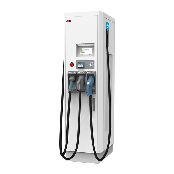
TER R A 54 / 54 H V C H AR G ER 2.1.2 Outside view Door handle / lock Charge outlet: DC connector and DC cable Emergency stop Air inlet Display / HMI Border cover RFID card reader Air outlet (backside) 2.1.3 Inside view Cable gland plate... -
Page 12: Geometry Of Infrastructure
TER R A 54 / 54 H V C H AR G ER Geometry of infrastructure 2.2.1 Required space for placing and maintaining the Terra 54 The Terra 54 requires a space of 1585 x 1480 mm. This space is calculated as follows: - Size Charger W x D x H: 565 x 780 x 1900 mm. -
Page 13: Bollards
TER R A 54 / 54 H V C H AR G ER 2.2.3 Bollards It is advised to place bollards around the charger to protect the charging station against cars hitting and damaging the cabinet. 2 0 18 - 10 - 03 13/40... -
Page 14: Electrical Engineering
Requirements External RCD NOTICE External RCD not included in delivery scope Upstream RCD’s are explicitly excluded from ABB’s delivery scope and belong to the scope of the installation company. The locally certified installation company can base the RCD device type, amongst other external factors, on below charger characteristics. -
Page 15: Conductor And Cable Diameter
(high immunity). As a suggestion to the installation company ABB recommends the following RCD type which will work in most grid situations: (1) ABB make F204 B S-125/0,3 code: 2CSF204823R3950. It is the responsibility of your installation company to select the right device. - Page 16 TER R A 54 / 54 H V C H AR G ER Example of cable lug to be used 2 0 18 - 10 - 03 16 /40...
-
Page 17: Site Design
TER R A 54 / 54 H V C H AR G ER Site design A site for EV charging can be designed in many different setups. This section is intended to give some useful information on the placement of a charger with respect to parking spaces and the vehicle inlets for the charging cable. - Page 18 TER R A 54 / 54 H V C H AR G ER This makes some positions of the charger with respect to the parking space more favorable than others. Please keep this in mind when designing a site. Some possible situations are showed below: 2 0 18 - 10 - 03 18/40...
-
Page 19: Site Construction
Depending on the situation and cable type, the cables must be embedded in the ground with or without a cable duct. See section Cabling on Page 20. 4.3.2 Placing the ABB Standard or locally manufactured prefab concrete foundation Make a hole in the ground with a minimum of the dimensions shown. -
Page 20: Instructions For A Custom Foundation (Footprint)
The preferred method of communication is to use the wireless 2/3G modem that is inte- grated into the Charger. A customer SIM card is not required, a subscription for the SIM card is provided by ABB for selected countries. If there is no wireless signal available, a standard wired internet connection is required. This... - Page 21 128 kb/s download: 4 Mmb/s. • Recommended availability: 99,9%. The connection must be available for the ABB service engineer and the NOC. • • Please contact ABB for a specific configuration. In case the separate internet connection is not used, please assure the cable entry hole is closed, to assure the IP54 grade of the cabinet, and prevent insects and small animals to en- ter the cabinet.
-
Page 22: Receiving, Placing And Connecting
If damage is discovered, leave cabinet in original package and request immediate inspection from carrier within 3 days of delivery. 4. Contact ABB The Netherlands by mail (service.evci@nl.abb.com) or phone (+3170 3076 201) to notify us about your findings. Unpacking cabinet, mounting preparations 5.2.1... -
Page 23: Mounting Preparations
TER R A 54 / 54 H V C H AR G ER Remove the outside shrink wrap. Remove the plastic protection profiles. Remove the innerside shrink wrap. 5.2.2 Mounting preparations Remove border covers Preconditions: • Tools: Allen key size 4. Remove the bolts (C) of the border covers. -
Page 24: Move Cabinet To Position
TER R A 54 / 54 H V C H AR G ER Open the cabinet front door (D). 4. Open the side door (E) via the front door. 5. Loosen and remove the cable gland (F) for the power cable. 6. -
Page 25: Move Cabinet With Hoist
TER R A 54 / 54 H V C H AR G ER DANGER Hazardous voltage Make sure the main switch of the power supply group for the product is set to the OFF position. Do a voltage check to make sure there is no electrical power on the cables or on the system. -
Page 26: Move Cabinet Forklift Truck
TER R A 54 / 54 H V C H AR G ER 5.3.3 Move cabinet forklift truck 1. Move the forks of the forklift truck in the gaps at the side of the Terra 54. 2. Move the Terra 54 carefully to its location. Mounting the cabinet Preconditions: •... -
Page 27: Mounting The Cabinet
TER R A 54 / 54 H V C H AR G ER Cables 5.4.2 Mounting the cabinet 1. Carefully lower the Terra 54 onto its location. 2. Make sure not to entrap the cable(s). 3. Make sure that the cabinet is aligned to the tapped holes. 4. -
Page 28: Install Border Covers
TER R A 54 / 54 H V C H AR G ER In case the separate internet connection is not used, please assure the cable entry hole is closed, to assure the IP54 grade of the cabinet, and prevent insects and small animals to en- ter the cabinet. -
Page 29: Connect Power Cable
TER R A 54 / 54 H V C H AR G ER 1. Cut the PE wire of the power cable to the correct length to reach the PE connector. NOTICE For safety, it is recommended to make the PE wire longer than the phase wires. - Page 30 7. Install the covers back onto the connector. WARNING Leave the main switch switched off. The Terra 54 is not ready for use yet. Please contact the ABB Service department at least one week in advance to make an appointment for com- missioning.
- Page 31 TER R A 54 / 54 H V C H AR G ER • Tools: Network cable pliers, RJ45 connector; network cable straight, 1. Cut the network cable to the correct length to reach the Ethernet connector. connector is located behind the right side door, near the bottom of the charger. 2.
-
Page 32: Commissioning
A certified service engineer from the ABB Service department or a trained engineer by ABB is required to perform the commissioning. During this commissioning the safety and the func- tioning of the charger will be tested. - Page 33 • Change Deliver status to <SAT>. After completing the Site Acceptance Test, ABB’s Network Operation Center will be triggered to perform a final check on the connection and configuration of the charger. Upon approval the charger will be operational and initialized for use.
-
Page 34: Cleaning Of The Cabinet
TER R A 54 / 54 H V C H AR G ER Cleaning of the cabinet Cleaning of the cabinet The Terra 54 Charge Station is powder coated. This coating must be kept in good condition. Clean the Terra 54 Charge Station three times a year in the following way: Remove rough dirt by spraying with low-pressure tap water. -
Page 35: Technical Data
TER R A 54 / 54 H V C H AR G ER Technical Data Electrical data Input Supply voltage 3 phase, 400 V AC: PE, N, L1, L2, L3 Input voltage range 400 V AC +/- 10% (50 Hz or 60 Hz) Maximum rated input current &... -
Page 36: Mechanical Data
TER R A 54 / 54 H V C H AR G ER Max AC output current 3 x 32 A / 3 x 63 A Output Voltage Range 400 V +/- 10% General EN61851-23 / DIN 70121 CCS 2 CHAdeMO 1.0 DC connection standard 3.9 meters +/- 10% DC cable length... -
Page 37: Certifications
TER R A 54 / 54 H V C H AR G ER Altitude 2000 m max. Certifications CE Certification EMC: EN 61000-6-3 Class B emission; EN 61000-6-2 immunity (see certificate) LVD: IEC 61851-1, IEC 62196, IEC 60950, EN 61010, EN 60335 (see certificate) RFID: ISO/IEC 14443 A/B, ISO/IEC15693, ISO 18902 NFC 2 0 18 - 10 - 03 37/40... -
Page 38: Contact Information
TER R A 54 / 54 H V C H AR G ER Contact information NOTICE In case of problems Please contact your local ABB Service organization or Service partner for first line problem analysis and solving. In case they cannot solve the problem, they will contact the second line Service organization. -
Page 39: Appendix A - Concrete Foundation
TER R A 54 / 54 H V C H AR G ER Appendix A – Concrete foundation 10.1 Terra 53/54 drawing 2 0 18 - 10 - 03 3 9/40... -
Page 40: Appendix B - Disposal Instruction
TER R A 54 / 54 H V C H AR G ER Appendix B - Disposal instruction 11.1 Directive on Waste Electrical and Electronic Equipment (WEEE – 2012/19/EU) 2 0 18 - 10 - 03 40/40...