
Summary of Contents for Kronos H-46 Series
- Page 1 BATTERY-POWERED STRAPPING TOOL KRONOS H-46 H-46A H-46B Original Instruction 02/2018...
-
Page 3: Table Of Contents
CONTENTS PART I 1. General Safety Rules ................A1 2. Functional Unit ................... A3 3. Technical Data ..................A4 4. Operation Elements ................A5 5. Operation .................... A6 6. Maintenance ..................A15 7. Troubleshooting ................A16... - Page 4 PART II 1. Wiring Diagram .................. B1 PART III 1. Tensioning Unit .................. C1 2. Gripper Unit ..................C9 3. Linkage Unit ..................C11 4. Sealing & Cutting Unit ..............C13 5. Body Frame Unit ................C17 6. Battery Unit ..................C19...
-
Page 5: Part I
PART I... -
Page 6: General Safety Rules
1. General Safety Rules Warning: DO NOT attempt to operate the tool until you have read and understood all instructions and safety rules contained in this manual. Failure to comply may result in accidents involving Save this owner’s manual for future fire, electric shock, or serious personal injury. - Page 7 f. Dress properly. Do not wear loose clothing or jewellery. Keep your hair, clothing and gloves away from moving parts. Loose clothes, jewellery or long hair can be caught in moving parts. Power Tool Use and Care a. Do not use the tool if the switch does not turn it on and off. Any tool that cannot be controlled with the switch is dangerous and must be repaired.
-
Page 8: Functional Unit
2. Functional Unit 6. Battery Unit 2. Gripper Unit 3. Linkage Unit 5. Body Frame Unit 4. Sealing & Cutting Unit 1. Tensioning Unit -A3-... -
Page 9: Technical Data
3. Technical Data Model number H-46A-12 H-46A-16 H-46B-16 H-46B-19 remarks Battery Type BOSCH Li-Ion , 18Vdc 4.0Ah About 40 minutes Charging Time (after 20 minutes, approx. 70% charge capacity) Strapping Speed 5 sec/cycle (Auto) Strap Width 11-13mm 15-16mm 15-16mm 19mm Strap Type PET, PP PP:0.6mm -1.05mm... -
Page 10: Operation Elements
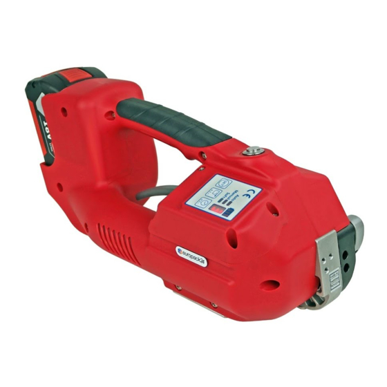
4. Operating Elements Sealing switch Operation Panel Tension switch (Auto) Battery Handle lever A :Operation mode indicator B :Operation mode set button C :Tension force adjustment button D :Sealing time adjustment button E :Battery power indicator F :Digital display for Tension , Sealing time, error code…. -A5-... -
Page 11: Operation
5. Operation 5.1 Charging the Battery When you receive battery, its capacity may not be sufficient. Please charge fully before using. Insert battery into battery charger slot. The charging process and error functions are indicated by a green and a red light . For detailed information, refer to the operating instructions for the battery and battery charger. - Page 12 5.2 Inserting the Battery Insert the battery from the top downward to the bottom into the battery slot of the tool until hear the “click” sound. (refer to Fig. b). (Fig. b) Removing the Empty Battery If the Battery power indicator on Operation Panel is flash, that means the battery is exhausted.
- Page 13 5.3 Adjustments Operation Panel 5.3.1 Adjusting the Operation mode (Auto) → (Semi) → (Manu) → → → Press and hold the button “B” for 1 sec, if the tool beeps and flashes the indicator, the tool is for adjusting the operation mode now. Press then release the button “B” to change the mode, and the mode sequence is as the cycle above.
- Page 14 Strap Tension Force Correspondence Table: H-46A normal lbs 198 soft lbs 88 H-46B kg 120 normal lbs 264 soft lbs 88 5.3.3 Adjusting the Sealing Time Press and hold the button “D” for 1 sec, if the tool beeps, the tool is for adjusting the sealing time now.
- Page 15 5.6 Tensioning and Sealing the Straps 5.6.1 Auto mode Press down the tension switch “1” ,hold on or leave the tension switch,the tool will tensioning till desired tension is reached. Then the tool will do sealing and cutting by itself. After the audible signal sound, cycle is finished.
- Page 16 5.7 Removing the Tool Pull up the handle lever, pull the tool right / backwards and off the strapping. 5.8 Seal - Control A regular control of the seal is necessary. The seal can be examined visually. Make a seal, peel it apart and examine it as follows: Correct Seal The seal must be completely welded over the whole width of the strap on a length.
- Page 17 Caution! During use of various width strap, it can happen that the welding is not uniform. If this happens you can set the welding area adjustment the screw (pic.D1 -D2) If welding is mostly on the external strap side (pic.D3) to unscrew slightly the external set screw and if it need screw slightly the internal set screw to have a uniform welding (pic.D4) If welding is mostly on the internal strap side (pic.D5) to unscrew slightly the internal set screw and if it needs screw slightly the external set screw to have a uniform welding...
- Page 18 5.9.2 Cycle counter Press and hold sealing switch and “SET” for 1 second, the digital display will show the strapping cycle. The counter number contains 6 digits which are displayed orderly from millions digit to one digit after showing the “-” symbol, and each digit displays 1 second with a 0.5-second blank interval.
- Page 19 5.10.2 SUSPENSION HOOK The tool could be equipped with a suspension hook(H46-50300). The hook must be fixed to the tool by two screws (included) in vertical or horizontal position 5.11 Change strap width Strap stop (Front) Strap stop (Rear) (#3) (#9) H-46A-12 H46-10610...
-
Page 20: Maintenance
6. Maintenance Please take off the battery before doing maintenance. Daily: Use air gun to clean the area around Tensioning Wheel (H46-10700/H46-10710) and Gripper (H46-10900) and the area around Cutter (H46-40900) daily. Be sure to use the air gun by blowing the debris from the left side to avoid any debris blowing to inside of the tool. -
Page 21: Troubleshooting
DISPOSAL The power tool, accessories and packaging materials should be sorted for environmental-friendly recycling. Do not dispose of power tools into household waste! According the European Guideline 2002/96/EC for Waste Electrical and Electronic Equipment and its implementation into national right, power tools that are no longer usable must be collected separately and disposed of in an environmentally correct manner. - Page 22 (2) The strap can not be cut completely a. The sealing time might be set too short. b. The strap is not thread correctly so a small part of the strap is not cut completely. c. The Cutter (H46-40900) is worn. (3) Error Code E01:M1 over load.
- Page 23 PART II...
-
Page 24: Wiring Diagram
1 Wiring Diagram -B1-... - Page 26 PART III...
- Page 28 TENSIONING UNIT H46-10000 (For H-46A) H46-10010 REF. PART NO. DESCRIPTION Q'TY REMARKS H46-10000 Tensioning Unit (For H-46A, 12mm) H46-10010 Tensioning Unit (For H-46A, 16mm) H46-10200 Bracket A H46-10300 Swivel Shaft H46-10400 Front Gear A H46-10500 Cam Disk H46-10600 Strap Stop (For 16mm) H46-10610 Strap Stop (For 12mm) H46-10700...
-
Page 29: Tensioning Unit
TENSIONING UNIT H46-10000 (For H-46A) H46-10010 REF. PART NO. DESCRIPTION Q'TY REMARKS HSS0303N HSS, M3×3 (N) HSS0305 HSS, M3×5 HSS0406GN HSS, M4×6 (G)(N) FHS0308N FHS, M3×8 (N) FHS0410N FHS, M4×10 (N) THS0405N THS, M4×5 (N) THS0408N THS, M4×8 (N) THS0412N THS, M4×12 (N) HBS0412N HBS, M4×12 (N) - Page 30 -C4- -C4-...
- Page 32 TENSIONING UNIT H46-10020 (For H-46B) H46-10030 REF. PART NO. DESCRIPTION Q'TY REMARKS H46-10020 Tensioning Unit (For H-46B, 16mm) H46-10030 Tensioning Unit (For H-46B, 19mm) H46-10210 Bracket B H46-10300 Swivel Shaft H46-10410 Front Gear B H46-10500 Cam Disk H46-10600 Strap Stop (Only 16mm) H46-10710 Tensioning Wheel B H46-10800...
- Page 33 TENSIONING UNIT H46-10020 (For H-46B) H46-10030 REF. PART NO. DESCRIPTION Q'TY REMARKS HSS0303N HSS, M3×3 (N) HSS0305 HSS, M3×5 HSS0406GN HSS, M4×6 (G)(N) FHS0308N FHS, M3×8 (N) FHS0410N FHS, M4×10 (N)(Only 16mm) THS0405N THS, M4×5 (N) THS0408N THS, M4×8 (N) THS0412N THS, M4×12 (N)(Only 16mm) HBS0412N...
- Page 34 -C8- -C8-...
-
Page 36: Gripper Unit
GRIPPER UNIT H46-20000 REF. PART NO. DESCRIPTION Q'TY REMARKS H46-20200 M2 Bracket H46-20300 Shaft H46-20400 Eccentric Shaft H46-20500 Lever H46-20600 Lever H46-20700 Upper Linkage H46-20800 Shaft H46-21000 Lower Linkage H46-21100 Shaft H46-21310 Bracket H46-21400 Collar (φ5) H46-21410 Collar (φ6) H46-21600 Bushing H46-40600 H45-20080... -
Page 38: Linkage Unit
LINKAGE UNIT H46-30000 REF. PART NO. DESCRIPTION Q'TY REMARKS H46-30100 Handle Lever H46-30200 Handle Cam H46-30300 Block H46-30400 Toothed Lever H46-30600 Pawl Wheel H46-30700 Pawl Shaft H46-30800 Set Screw H46-30900 Spring H46-31000 Spring H44-10070 Washer H45-10250 Washer ER03 Snap Ring, E-3 MB1008 Metal Bushing, 1008 MB1010... -
Page 40: Sealing & Cutting Unit
SEALING & CUTTING UNIT H46-40000 REF. PART NO. DESCRIPTION Q'TY REMARKS H46-40100 Motor Support H46-40200 Swivel Bracket H46-40300 Welding Eccentric H46-40400 Motor Support H46-40500 Welding Shoe H46-40800 Pully H46-40900 Cutter H46-41000 Welding Stop Gripper H46-41100 Bolt H46-41500 Washer H46-41600 Gear H46-41700 Washer H46-42000... - Page 41 SEALING & CUTTING UNIT H46-40000 REF. PART NO. DESCRIPTION Q'TY REMARKS HBS0430HN HBS, M4×30 (H)(N) HBS0545HN HBS, M5×45 (H)(N) SW04 SW, M4 SW05 SW, M5 -C15-...
- Page 42 -C16- -C16-...
-
Page 44: Body Frame Unit
BODY FRAME UNIT H46-50000 H46-50010 REF. PART NO. DESCRIPTION Q'TY REMARKS Body Frame Unit (For H-46A) H46-50000 Body Frame Unit (For H-46B) H46-50010 H46-50100 Body Frame (For H-46A) H46-50110 Body Frame (For H-46B) H46-50300 Suspension Bracket (Option) H46-50800 Cover Front H46-50900 Cover Rear H46-51000... -
Page 46: Battery Unit
BATTERY UNIT H46-60000 H46-60010 REF. PART NO. DESCRIPTION Q'TY REMARKS H46-60000 Battery Unit (For H-46A, 220V/230V/240V) H46-60010 Battery Unit (For H-46A, 110V) H46-60020 Battery Unit (For H-46B, 220V/230V/240V) H46-60030 Battery Unit (For H-46B, 110V) H46-60100 Control Panel H46-60200 Push Button Switch H46-60300 Battery H46-60400...
Need help?
Do you have a question about the H-46 Series and is the answer not in the manual?
Questions and answers
H46A strapper E10 error code.