Table of Contents
Advertisement
Model No. WEBE4067.0
Serial No.
Write the serial number in the
space above for future reference.
Serial Number Decal (under seat)
QUESTIONS?
As a manufacturer, we are com-
mitted to providing complete cus-
tomer satisfaction. If you have
questions, or if parts are missing,
PLEASE DO NOT CONTACT
THE STORE; please contact
Customer Care.
IMPORTANT: You must note the
product model number and
serial number (see the drawing
above) before contacting us:
CALL TOLL-FREE:
1-877-992-5999
Mon.–Fri. 6 a.m.–6 p.m. MST
Sat. 8 a.m.–4 p.m. MST
ON THE WEB:
www.weiderservice.com
CAUTION
Read all precautions and instruc-
tions in this manual before using
this equipment. Save this manual
for future reference.
USER'S MANUAL
Visit our website at
www.proform.com
new products, prizes,
fitness tips, and much more!
Visit our website at
www.healthrider.com
new products, prizes,
fitness tips, and much more!
Visit our website at
www.nordictrack.com
new products, prizes,
fitness tips, and much more!
Visit our website at
www.weiderfitness.com
new products, prizes,
fitness tips, and much more!
Advertisement
Table of Contents

Related Manuals for WEIDER CLUB C725


Summary of Contents for WEIDER CLUB C725
- Page 1 Model No. WEBE4067.0 Serial No. USER’S MANUAL Write the serial number in the space above for future reference. Visit our website at www.proform.com Serial Number Decal (under seat) new products, prizes, fitness tips, and much more! QUESTIONS? As a manufacturer, we are com- mitted to providing complete cus- tomer satisfaction.
- Page 2 TABLE OF CONTENTS WARNING DECAL PLACEMENT ............. 2 IMPORTANT PRECAUTIONS .
- Page 3 IMPORTANT PRECAUTIONS WARNING: To reduce the risk of serious injury, read all important precautions and instructions in this manual and all warnings on the weight bench before using the weight bench. ICON assumes no responsibility for personal injury or property damage sustained by or through the use of this product.
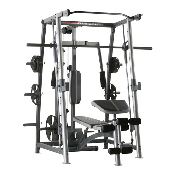
- Page 4 ® CLUB manual. To help us assist you, note the product model C725 weight bench. The weight bench offers an number and serial number before contacting us. The impressive selection of exercise stations designed to model number and the location of the serial number develop every major muscle group of the body.
- Page 5 PART IDENTIFICATION CHART See the drawings below to identify small parts used in assembly. The number in parentheses by each drawing is the key number of the part, from the PART LIST near the end of this manual. Note: Some small parts may have been preattached.
- Page 6 M4 x 10mm Self- M6 x 20mm M8 x 15mm M8 x 25mm Screw (122) tapping Screw (79) Shoulder Bolt (143) Button Screw (112) M6 x 40mm Screw (140) M6 x 8mm M8 x 10mm Set Screw (99) Set Screw (49) M6 x 48mm Button Bolt (124) 33mm Spacer (52)
- Page 7 ASSEMBLY • For help identifying small parts, use the PART Make Assembly Easier IDENTIFICATION CHART on pages 5 and 6. Everything in this manual is designed to ensure • As you assemble the weight bench, make sure all parts are oriented as shown in the drawings. that the weight bench can be assembled suc- cessfully by almost anyone.
- Page 8 2. Attach the Seat (33) to the Bench Frame (1) with four M6 x 20mm Screws (122). 3. Attach the Front Leg (3) to the Bench Frame (1) with two M10 x 110mm Screws (117) and two M10 Washers (83). See step 1.
- Page 9 5. Apply grease to an M10 x 175mm Bolt (42). Attach the Backrest Frames (8) to the Bench Frame (1) with the Bolt, two M10 Washers (83), a Grease 33mm Spacer (52), and an M10 Nylon Locknut (116). Set the end of the Backrest Post (7) in one of the slots in the Bench Frame.
- Page 10 8. Slide two Foam Pads (35) onto the Front Leg (3). Then, press two Pad Caps (37) into the Foam Pads. 9. Insert the two Pad Tubes (51) into the Leg Lever (4). Slide two Foam Pads (35) onto each Pad Tube.
- Page 11 11. Identify the Left Rear Upright (12) by looking at the locations of the hooks. Orient the Left Rear Upright as shown, and attach it to the Rear Base (9) with two M10 x 70mm Button Bolts (97), two M10 Washers (83), and an M10 Nylon Locknut (116).
- Page 12 13. Orient one of the Front Uprights (11) so that the slots are on the indicated side. Attach the Front Upright to the left Side Base (14) with two M10 x 100mm Button Screws (129) and two M10 Washers (83). Attach the other Front Upright (11) to the right Side Base (14) in the same way.
- Page 13 15. Orient the Center Upright (13) as shown. Attach the Center Upright to the Rear Base (9) with two M10 x 85mm Button Bolts (125), two M10 Washers (83), and two M10 Nylon locknuts (116). Do not Tighten the Nylon Locknuts yet. 16.
- Page 14 18. Press the Weight Bumper (30) down onto the Weight Carriage Base (20). Next, attach the Weight Carriage Upright (21) to the Weight Carriage Base (20) with two M10 x 85mm Button Bolts (125). Do not tighten the Button Bolts yet. 19.
- Page 15 21. Attach a Spotter Hook (115) to a Barbell Spotter (109) with an M10 x 26mm Button Bolt (119) and an M10 Nylon Locknut (116). Do not overtighten the Nylon Locknut; the Spotter Hook must pivot easily. Next, slide a Barbell Spotter Bumper (111) and the Barbell Spotter (109) onto the left Barbell Guide (25).
- Page 16 23. Attach the Top Frame (17) to the Left Rear Upright (12) with two M10 x 62mm Bolts (96), two M10 Washers (83), and two M10 Nylon Locknuts (116). Do not tighten the Nylon Locknuts yet. Make sure that the heads of the Bolts are inside the Left Rear Upright.
- Page 17 26. Attach the Weight Carriage Frame (18) to the Center Upright (13) with two M10 x 85mm Button Bolts (125) and two M10 Washers (83). Do not tighten the Button Bolts yet. 27. Attach the Weight Carriage Frame (18) to the Weight Carriage Upright (21) with two M10 x 75mm Button Bolts (130) and two M10 Washers (83).
- Page 18 29. Identify the Right Arm (23) and insert it into the Arm Frame (24). See the inset drawing. Make sure that the welded pin on the Right Arm is behind the rod on the Arm Frame as shown. Apply grease to an M10 x 94mm Bolt (134). Grease Attach the Right Arm (23) to the Arm Frame (24) with the Bolt and an M10 Thin Nylon Locknut...
- Page 19 32. Insert a Phillips screwdriver into the indicated hole in a Trunnion (70), and tighten the Trunnion into the Top Frame (17). Next, press a Top Frame Cap (16) onto the Top Frame. Attach the other Trunnion (70) and the other Top Frame Cap (16) in the same way.
- Page 20 35. See the CABLE DIAGRAM on page 34 to iden- tify the cables as you assemble them. Grease Identify the Arm Cable (82). Apply grease to an M8 x 25mm Shoulder Bolt (143). Attach the Arm Cable to the Left Arm (22) with the Shoulder Bolt and an M8 Nylon Locknut (139).
- Page 21 38. Wrap the Arm Cable (82) over a “V”-pulley (75). Attach the “V”-pulley, a Large Cable Trap (77), and two Full Pulley Guards (76) to the other side of the bracket on the Center Upright (13) with an M10 x 63mm Button Bolt (133), an M10 Washer (83), and an M10 Nylon Locknut (116).
- Page 22 41. Attach an M6 x 48mm Button Bolt (124) and an M6 Nylon Locknut (150) to the Swivel Bracket (31) and the Bracket Guard (149) as shown. Make sure that the High Cable (81) is between the Button Bolt and the Small Pulley (74). Next, wrap the High Cable (81) around a Small Pulley (74).
- Page 23 44. Wrap the High Cable (81) under a Small Pulley (74). Attach the Small Pulley, a Small Cable Trap (93), and two Half Pulley Guards (91) to the sec- ond hole from the top of the “U”-bracket (90) with an M10 x 52mm Button Bolt (135) and an M10 Nylon Locknut (116).
- Page 24 46. Wrap the High Cable (81) around a Small Pulley (74). Attach the Small Pulley to the indicated bracket on the Weight Carriage Frame (18) with an M10 x 45mm Button Bolt (131) and an M10 Nylon Locknut (116). Bracket 47.
- Page 25 48. Wrap the High Cable (81) over a Small Pulley (74). Insert the Small Pulley and the Cable into the remaining Bracket Guard (149); make sure that the Cable is under the indicated rod. Next, attach the Bracket Guard and the Small Pulley inside the Swivel Bracket (31) with an M10 x 60mm Button Bolt (136), two M10 Washers (83), two Pulley Caps (73), two 6.5mm Spacers (100),...
- Page 26 51. Wrap the Rear Cable (94) under a Small Pulley (74). Attach the Small Pulley, a Small Cable Trap (93), and two Half Pulley Guards (91) at the holes closest to either end of the two Pulley Plates (92) with an M10 x 52mm Button Bolt (135) and an M10 Nylon Locknut (116).
- Page 27 54. Wrap the Low Cable (80) over a Small Pulley (74). Attach the Small Pulley and two Half Pulley Guards (91) to the Double “U”-bracket (98) with an M10 x 45mm Button Bolt (131) and an M10 Nylon Locknut (116). Make sure that the Half Pulley Guards are oriented as shown.
- Page 28 57. Wrap the Low Cable (80) under a Small Pulley (74). Attach the Small Pulley and two Half Pulley Guards (91) to the Weight Carriage Base (20) with an M10 x 45mm Button Bolt (131) and an M10 Nylon Locknut (116). Make sure that the Half Pulley Guards are oriented as shown.
- Page 29 ADJUSTMENT This section explains how to adjust the weight bench. See the EXERCISE GUIDELINES on page 35 for impor- tant information about how to get the most benefit from your exercise program. Also, refer to the accompanying exercise guide to see the correct form for several exercises. ADJUSTING THE BACKREST To adjust the position of the Backrest (32), lift the indi- cated handle on the Backrest Post (7).
- Page 30 USING THE FREE WEIGHT BAR Before using the free weight bar (not shown), set the Weight Rests (26) at the lowest point to which you want the barbell to move. To do this, hold a Weight Rest (26) and pull out the Upright Pin (28).
- Page 31 USING THE LOCKING BAR Grip the Locking Bar (114) with both hands. Turn the Hook Locking Bar until the two hooks disengage the slots in the Front Uprights (11). Raise or lower the Locking Bar to a new position and turn it until the hooks engage the slots in the Front Uprights.
- Page 32 ATTACHING THE ACCESSORIES TO THE HIGH PULLEY STATION To use the high pulley station, first place the desired weights on the Weight Carriage (see page 31). Next, attach the Lat Bar (59) to the High Cable (81) with a Cable Clip (63). For some exercises, the Chain (62) should be attached between the Lat Bar and the Cable with two Cable Clips.
- Page 33 MAINTENANCE Make sure that all parts are properly tightened each time the weight bench is used. Replace any worn parts immediately. The weight bench can be cleaned with a damp cloth and a mild, non-abrasive detergent; do not use solvents to clean the weight bench. TIGHTENING THE CABLES Woven cable, the type of cable used on the weight bench, can stretch slightly when it is first used.
- Page 34 CABLE DIAGRAM The diagram below shows the proper routing of the cables. The numbers in each drawing show the proper rout- ing for that cable. Use the diagram to make sure that the cables, cable traps, and pulley guards are assembled correctly.
- Page 35 EXERCISE GUIDELINES THE FOUR BASIC TYPES OF WORKOUTS PERSONALIZING YOUR EXERCISE PROGRAM Muscle Building Determining the appropriate length of time for each To increase the size and strength of your muscles, workout, and the numbers of repetitions and sets to push them close to their maximum capacity.
- Page 36 COOLING DOWN The repetitions in each set should be performed smoothly and without pausing. The exertion stage of each repetition should last about half as long as the End each workout with 5 to 10 minutes of stretching. return stage. Proper breathing is important. Exhale Include stretches for both your arms and legs.
- Page 37 EXERCISE WEIGHT SETS REPS MONDAY Date: TUESDAY AEROBIC EXERCISE Date: EXERCISE WEIGHT SETS REPS WEDNESDAY Date: THURSDAY AEROBIC EXERCISE Date: EXERCISE WEIGHT SETS REPS FRIDAY Date: Make photocopies of this page for scheduling and recording your workouts.
- Page 38 PART LIST—Model No. WEBE4067.0 R0907A Key No. Qty. Description Key No. Qty. Description Bench Frame Pad Tube Rear Stabilizer 33mm Spacer Front Leg M8 Jamnut Leg Lever Cable Eyelet Weight Tube Cable Stop Backrest Post Handle M10 x 20mm Button Bolt Backrest Post Pulley Handle Backrest Frame...
- Page 39 Key No. Qty. Description Key No. Qty. Description Barbell Collar Weight Clip Barbell Adapter M10 x 63mm Button Bolt 48mm x 2mm Round Inner Cap M10 x 94mm Bolt Right Barbell Carriage M10 x 52mm Button Bolt Bar Slide Bushing M10 x 60mm Button Bolt Barbell Bushing Leg Lever Spacer...
- Page 40 EXPLODED DRAWING A—Model No. WEBE4067.0 R0907A...
- Page 41 EXPLODED DRAWING B—Model No. WEBE4067.0 R0907A...
- Page 42 EXPLODED DRAWING C—Model No. WEBE4067.0 R0907A 116 83 138 76 75 77...
- Page 43 EXPLODED DRAWING D—Model No. WEBE4067.0 R0907A...
- Page 44 ORDERING REPLACEMENT PARTS To order replacement parts, please see the front cover of this manual. To help us assist you, be prepared to pro- vide the following information when contacting us: • the model number and serial number of the product (see the front cover of the manual) •...
Need help?
Do you have a question about the C725 and is the answer not in the manual?
Questions and answers
What is the barbell weight for the Weider C725? Is there a counterbalancing system in the Weider C725?
The Weider Club C725 uses a barbell (part 113) and requires equal weight on each side of the barbell or weight carriage (part 19) for balance during use. Weights are added to the barbell adapters (part 102) or the weight carriage and secured with weight clips (part 132). The maximum weight capacity is 310 lbs (140 kg) for the barbell and 150 lbs (68 kg) for the weight carriage. There is no separate counterbalancing system mentioned; proper balance is maintained by evenly distributing the weights.
This answer is automatically generated