
Related Manuals for LFA RTP 9


Summary of Contents for LFA RTP 9
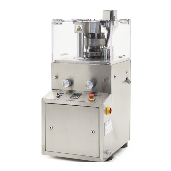
- Page 1 RTP 9® Tablet Press User Manual We don’t just sell machines— we provide service.
-
Page 2: Copyright Notice
Copyright Notice © LFA Machines Oxford Limited, published in 2019 by LFA Machines Oxford Limited 2019. Registered in England and Wales, company number 08428898, registered office for service Demar House 14 Church Road East Wittering, Chichester, West Sussex, PO20 8PS. -
Page 3: Important Safety Information
• Ensure that machine is secure with anti- For personal protection while transporting the vibration feet on the workspace floor. RTP 9®, abide by these actions: • Inspect machine before use. • Use an engine hoist to lift the machine. -
Page 4: Important Safety Information
Important Safety Information READ THIS BEFORE OPERATING MACHINE Symbols WARNING WARNING This signals potential risk for personal injury. This signals potential risk for electrical shock. CAUTION This signals potential risk for damage to the machine or other parts. Modes for Stopping In the case of an emergency during automatic operation, immediately unplug the RTP 9®... -
Page 5: Table Of Contents
Lower Tracking Lower Roller Cam Troubleshooting Common Machine/Part Issues Common Tablet Issues De-Jamming the RTP 9® Cleaning Storing the RTP 9® Appendix Glossary Description of RTP 9® Parts Food Grade Point of Contact Parts Technical Specifications Maintenance Checklist Diagrams Resources... -
Page 6: Rtp 9® Components
RTP 9® Components 1. Lower Punches 12. Fill Tray 2. Fill Tray Thumb Bolts 13. Fill Cam 3. Fill Cam Adjustment Worm Gear 14. Ejection Cam 4. Lower Roller Cam Shaft 15. Upper Support Columns 5. Upper Roller Cam Shaft 16. -
Page 7: Rtp 9® Electrical Components
RTP 9® Electrical Components WARNING Only qualified electricians should work with these controls. 1. The variable frequency drive (for motor speed) 2. Fuses 3. Breaker 4. Terminal block 5. Emergency stop 6. Power isolator switch... -
Page 8: Preface
The purpose of this document is to support your understanding of the RTP 9®’s components, features, functions, and design. With this manual, you will be able to successfully operate and maintain your RTP 9®... -
Page 9: Training
Using an online video chat system, an LFA technician can interact face-to-face with you and assist with your understanding of the machine. Or, if you prefer, LFA can provide training via phone for all customers who call the office. To set up a training, call or email your local LFA office:... -
Page 10: Installation
• Sterile shoe covers (food grade products only) The Appropriate Workstation for the Machine The floor on which the machine is to be placed must support the RTP 9®’s 260 kg (about 573 lbs) weight. The static floor loading limit is 0.8 kN/m2. - Page 11 The shipping crate will contain the following: 1. The assembled RTP 9® 2. The Tooling (already installed) 3. Power Transformer (for 110 V countries only)
- Page 12 4. Toolkit including: • Die Installation Bar • Die Removal Bar • Grease guns • Panel door keys • Socket set • Crosshead screwdriver • Flathead screwdriver • Wrenches • Allen key set...
- Page 13 Unpacking the RTP 9® Tools Needed • Flathead screwdriver • Hammer • Wrench set Instructions 1. Pry open each of the clips on the shipping container with a flathead screwdriver. 1.1 Note: Hammer the clips even further down to aid in removing the shipping container from the base.
-
Page 14: Assembly
Assembly The RTP 9® comes fully assembled. If you have a 110 V outlet, simply connect the RTP 9®'s electrical plug into the Power Transformer's outlet. After that, plug the Power Transformer into the power supply. The RTP 9® also comes with anti-vibration pads underneath its base's four corners. The anti-... -
Page 15: Positioning The Rtp 9
5. Feed the lifting straps through the four Upper Support Columns and around the Turret. 6. Bring together the lifting straps above the RTP 9® and into the engine hoist's lifting hook. 7. Carefully raise the RTP 9® with an engine hoist and guide it to your desired location. -
Page 16: Controls
Controls Basic Components Hopper Upper Roller Cam Upper Tracking Dies Upper and Lower Punches Fill Tray A description of the principal components follows: • The Hopper holds the dry materials that will be compressed. • The Fill Tray distributes the dry materials into the Die Bores and pushes tablets into the Ejection Tray. - Page 17 Control Console 1. Starts machine. 2. Stops machine and resets variable frequency driver. 3. Controls production speed. 4. Cuts off machine in emergency. 5. Adjusts fill depth. 6. Adjusts punch pressure.
- Page 18 RTP 9® Process The basic mechanism of the RTP 9® involves filling the Tooling (Dies, Upper Punches, and Lower Punches) with powder, compressing the powder, and ejecting the tablets. Filling the Tooling with Powder The dry materials are poured into the Hopper, which funnels the powder into the Fill Tray. As the machine operates, the Turret moves, which causes the Upper Punches to withdraw from the Dies.
- Page 19 4.1 Note: Manually press a tablet to avoid the chance of jamming the machine. 5. Remove the Handle and reinsert the panel door. 6. Plug in the RTP 9® to an electrical outlet. 6.1 Note: For 110 V outlet, plug in the Power Transformer and flip its switch.
-
Page 20: Settings And Adjustment
Settings and Adjustment The RTP 9®s settings can be adjusted. Tuning the machine can help with changing the tablets’ characteristics. Fill Depth At times, a tablet will be too small or too large, and its weight must change. This simple adjustment determines the tablet’s weight. - Page 21 Powder Flow from Hopper If you find that there is excess powder waste due to overflow, the Hopper will need to be adjusted. Tools and Materials Needed • Set of metric Allen keys • Disposable latex/rubber gloves (for food grade products and to protect hands from grease) •...
- Page 22 Fill Tray Height The size of granules in your powder can affect how smoothly dry materials are moved through the Fill Tray, which can affect how much powder is wasted. Sometimes this requires the Fill Tray's height to be adjusted. Tools and Materials Needed •...
- Page 23 • Disposable latex/rubber gloves (for food grade products and to protect hands from grease) • Hairnet and/or beard net (food grade products only) • Sterile shoe covers (food grade products only) WARNING: To prevent any potential personal injury, unplug the RTP 9® from the electrical outlet. Instructions Note: Wear latex/rubber gloves (and appropriate food grade attire if applicable) during this process.
- Page 24 • Disposable latex/rubber gloves (for food grade products and to protect hands from grease) • Hairnet and/or beard net (food grade products only) • Sterile shoe covers (food grade products only) WARNING: To prevent any potential personal injury, unplug the RTP 9® from the electrical outlet. Instructions Note: Wear latex/rubber gloves (and appropriate food grade attire if applicable) during this process.
-
Page 25: Maintenance
Maintenance To ensure that the RTP 9® will have a long operational life, maintenance is essential. This section includes methods for replacing parts, troubleshooting solutions, and how often to grease and clean your machines to keep its performance optimal. General Maintenance Prescriptions •... - Page 26 2. Remove the Upper Punches and Lower Punches. 2.1 For additional assistance, please refer to the Tooling removal instructions on page 33. 3. Lubricate the heads of the Upper Punches and Lower Punches with NLGI Grade 1 grease. 4. Lubricate the barrels of the Upper Punches and Lower Punches with SAE 10 oil. 5.
- Page 27 6. Open the lefthand side panel door. 7. Lubricate the Lower Roller Cam Shaft's grease nipple with NLGI Grade 2 grease. 8. Lubricate the the Pressure Adjustment Gears with NLGI Grade 2 grease. 9. Lubricate the Upper Roller Cam Shaft's grease nipple with NLGI Grade 2 grease.
- Page 28 10. Open the righthand side panel door. 11. Lubricate the Fill Adjustment Gear with NLGI Grade 2 grease.
- Page 29 Lubrication Schedule LFA recommends the following RTP 9® parts to be lubricated according to the following frequency: Part Location Image Frequency Type of Lubricant Inspect after every 3 months or 100,000 Ball bearings at the Drive Shaft tablets and apply if dry.
- Page 30 Part Location Image Frequency Type of Lubricant Inspect after every 3 Gear on Fill months or 100,000 Fill Adjustment Adjustment shaft tablets and apply if dry NLGI Grade 2 Gear (open righthand side If old, gritty grease is panel door) present, clean before lubricating.
-
Page 31: Dismantling For Repair And Replacement
Dismantling for Repair and Replacement Eventually due to wear and tear, some parts of the RTP 9® will need to be removed for repair and replacement. To prevent any delays in your tablet production, it is best practice to keep extra parts just in case. -
Page 32: Wear Parts And Causes Of Damage
LFA recommends having a spare set or two. Fill Tray On the RTP 9®, the Fill Tray spreads the powder over the Die Table and into the Die Bores. It is formed from cast brass with chrome plating and is designed to wear. -
Page 33: Tooling
Punches, and/or Dies you currently have are damaged, it is necessary to change the Tooling. To buy new Tooling from LFA, simply go to https://www.lfatabletpresses.com/products/tablet- press-tooling To watch a video of an RTP 9® Tooling change, go to https://www.lfatabletpresses.com/rtp-9- tooling-change Tools and Materials Needed •... - Page 34 3. Loosen the Fill Tray's Thumb Bolts with an Allen key and remove them by hand. 4. Remove the Fill Tray from the Turret. 5. Remove the rear side panel door. 6. Insert the Handle onto the Drive Belt Pulley socket.
- Page 35 7. Remove the Upper Tracking Key with an Allen key. 8. Rotate the Handle until an Upper Punch is where the Upper Tracking Key was previously. 9. Pull the Upper Punch upwards to remove it from the Turret.
- Page 36 10. Repeat steps 8-9 until all Upper Punches are removed. 11. Push up the the Lower Punch Insertion Disc underneath the Lower Punches and remove it from the RTP 9®. 12. Rotate the Handle until a Lower Punch is aligned with where the Lower Punch Insertion Disc was previously.
- Page 37 15. Rotate the Handle until a Die is aligned with where the Lower Punch Insertion Disc was previously. 16. Remove Die's set screw with an Allen key. 17. Hold the smaller part of the Die Removal Bar up through the hole where the Lower Punch Insertion Disc was previously and into the Turret.
- Page 38 20. Tap the end of the Die Removal Bar with a rubber mallet until the Die pops up from the Turret. 21. Repeat steps 15-20 until all Dies are removed. Note: To help ensure that the Dies are inserted correctly, LFA recommends using an Insertion Ring. You can order the Die Seat Cleaner and Insertion Ring on our website at https://www.
- Page 39 28. Insert a new Lower Punch up through the Lower Punch Insertion Disc's hole and into the new Die's Bore. 28.1 Note: Lubricate the barrel of the Lower Punch. 29. Place the new Lower Punch's head on the Lower Tracking. 30.
- Page 40 33. Insert a new Upper Punch through the top of the Turret. 33.1 Note: Lubricate the barrel of the Upper Punch. 34. Place the new Upper Punch's head on the Upper Tracking. 34.1 Note: Be sure that the new Upper Punch's head is above the Upper Tracking to prevent damage.
- Page 41 39.1 Note: Please refer to the Fill Tray Height adjustment instructions on page 22 for calibration. 40. Tighten the Fill Tray Thumb Bolts back onto the Fill Tray and RTP 9® by hand and/or with an Allen key. 41. Resecure the Perspex Casing and the Hopper with an Allen key.
-
Page 42: Fill Tray
• Disposable latex/rubber gloves (for food grade products and to protect hands from grease) • Hairnet and/or beard net (food grade products only) • Sterile shoe covers (food grade products only) WARNING: To prevent any potential personal injury, ALWAYS unplug the RTP 9® from the electrical outlet when replacing parts. Instructions Note: Wear latex/rubber gloves (and appropriate food grade attire if applicable) during this process. - Page 43 3. Loosen the Fill Tray Thumb Bolts with an Allen key or by hand and remove them. 4. Take off the Fill Tray from the Turret. 5. Remove the Fill Tray Scraper and Take-Off Blade from the Fill Tray with a crosshead screwdriver.
- Page 44 Replace the Fill Tray 6. Loosely attach the Fill Tray Scraper and Take-Off Blade on the new Fill Tray with a crosshead screwdriver. 7. Place the new Fill Tray on the Turret and align it with the Fill Tray Height Adjusters' holes. 8.
-
Page 45: Upper Tracking
• Disposable latex/rubber gloves (for food grade products and to protect hands from grease) • Hairnet and/or beard net (food grade products only) • Sterile shoe covers (food grade products only) WARNING: To prevent any potential personal injury, ALWAYS unplug the RTP 9® from the electrical outlet when replacing parts. Instructions Note: Wear latex/rubber gloves (and appropriate food grade attire if applicable) during this process. - Page 46 3. Loosen the Fill Tray's Thumb Bolts with an Allen key and remove them by hand. 4. Remove the Fill Tray from the Turret. 5. Remove the rear side panel door and insert the Handle onto the Drive Belt Pulley socket.
- Page 47 6. Remove the Upper Tracking Key with an Allen key. 7. Rotate the Handle until an Upper Punch is where the Upper Tracking Key was previously. 8. Pull the Upper Punch upwards to remove it from the Turret. 9. Repeat steps 7-8 until all Upper Punches are removed.
- Page 48 10. Remove the large nuts in the Upper Roller Cam Housing with a socket wrench. 11. Pull up the Upper Roller Cam Housing from the Turret. 11.1 Note: Be sure to keep a hold of the Upper Tracking to prevent it from falling. 12.
- Page 49 Replace the Upper Tracking 13. Place the new Upper Tracking onto the Upper Roller Cam Housing. 14. Reinsert the Upper Roller Cam Housing and the new Upper Tracking onto the RTP 9® tighten its nuts with a socket wrench. 14.1 Note: The correct tension for these nuts is 70-90 Nm.
- Page 50 15. Insert an Upper Punch through the top of the Turret. 16. Place the Upper Punch's head on the new Upper Tracking. 16.1 Note: Be sure that the Upper Punch's head is above the new Upper Tracking to prevent damage. 17.
- Page 51 20. Remove the Handle from the Drive Belt Pulley. 21. Place the Fill Tray back on the Turret. 21.1 Note: Please refer to the Fill Tray Height adjustment instructions on page 22 for calibration. 22. Tighten the Fill Tray Thumb Bolts back onto the Fill Tray and RTP 9®...
-
Page 52: Upper Roller Cam
Tools and Materials Needed • Set of metric Allen keys with ball ends • Socket wrench from RTP 9® Toolkit (36 mm) • New Upper Roller Cam part • Disposable latex/rubber gloves (for food grade products and to protect hands from grease) •... - Page 53 3. Loosen the Fill Tray's Thumb Bolts with an Allen key and remove them by hand. 4. Remove the Fill Tray from the Turret. 5. Remove the rear side panel door and insert the Handle onto the Drive Belt Pulley socket.
- Page 54 6. Remove the Upper Tracking Key with an Allen key. 7. Rotate the Handle until an Upper Punch is where the Upper Tracking Key was previously. 8. Pull the Upper Punch upwards to remove it from the Turret. 9. Repeat steps 7-8 until all Upper Punches are removed.
- Page 55 10. Remove the large nuts in the Upper Roller Cam Housing with a socket wrench. 11. Pull up the Upper Roller Cam Housing from the Turret. 11.1 Note: Be sure to keep a hold of the Upper Tracking to prevent it from falling.
- Page 56 12. Remove the Upper Roller Cam Pressure Adjuster with an Allen key. 13. Pull out the Upper Roller Cam Shaft from the Upper Roller Cam. 14. Remove the Upper Roller Cam from the Upper Roller Cam Housing.
- Page 57 17. Reinsert the Upper Roller Cam Pressure Adjuster onto the Upper Roller Cam Shaft and tighten its bolt with an Allen key. 18. Reinsert the Upper Roller Cam Housing onto the RTP 9® and tighten the nuts with a socket wrench.
- Page 58 19. Insert an Upper Punch through the top of the Turret. 20. Place the Upper Punch's head on the Upper Tracking. 20.1 Note: Be sure that the Upper Punch's head is above the Upper Tracking to prevent damage. 21. Rotate the Handle until the next Upper Punch can be inserted. 22.
- Page 59 24. Remove the Handle from the Drive Belt Pulley. 25. Place the Fill Tray back on the Turret. 25.1 Note: Please refer to the Fill Tray Height adjustment instructions on page 22 for calibration. 26. Tighten the Fill Tray Thumb Bolts back onto the Fill Tray and RTP 9®...
-
Page 60: Lower Tracking
• Set of metric Allen keys with ball ends • Crosshead screwdriver • Socket wrench (36 mm) from RTP 9® Toolkit • Disposable latex/rubber gloves (for food grade products and to protect hands from grease) • Hairnet and/or beard net (food grade products only) •... - Page 61 3. Loosen the Fill Tray's Thumb Bolts with an Allen key and remove them by hand. 4. Remove the Fill Tray from the Turret. 5. Remove the rear side panel door and insert the Handle onto the Drive Belt Pulley socket.
- Page 62 6. Remove the Upper Tracking Key with an Allen key. 7. Rotate the Handle until an Upper Punch is where the Upper Tracking Key was previously. 8. Pull the Upper Punch upwards to remove it from the Turret.
- Page 63 9. Repeat steps 7-8 until all Upper Punches are removed. 10. Push up the the Lower Punch Insertion Disc underneath the Lower Punches and remove it from the RTP 9®. 11. Remove the righthand panel door. 12. Rotate the Handle until a Lower Punch is aligned with where the Lower Punch Insertion Disc was previously.
- Page 64 15. Remove the large nuts in the Upper Roller Cam Housing with a socket wrench. 16. Pull up the Upper Roller Cam Housing from the Turret. 16.1 Note: Be sure to keep a hold of the Upper Tracking to prevent it from falling.
- Page 65 17. Pull up the Turret and set it aside. 18. Remove the Ejection Cam and the Fill Cam with an Allen key. 19. Turn the Fill Depth Knob clockwise to raise the Dosing Cam.
- Page 66 20. Pull up the Dosing Cam from the RTP 9®. Replace the Lower Tracking 21. Secure the new Lower Tracking components with an Allen key and a crosshead screwdriver. 22. Reinsert the Turret over the Main Drive Shaft. 23. Reinsert the Upper Cam Housing and tighten its screws with a socket wrench.
- Page 67 27. Repeat steps 24-26 until all the Lower Punches are inserted into the Turret. 28. Reinsert the Lower Punch Insertion Disc with the beveled side facing up. 28.1 Note: Manually turn the RTP 9®'s Turret for a couple of rotations to ensure that the Lower Punches are situated correctly.
- Page 68 32. Repeat steps 29-31 until all the Upper Punches are inserted into the Turret. 33. Resecure the Upper Tracking Key with an Allen key. 33.1 Note: Manually turn the RTP 9®'s Turret for a couple of full rotations to ensure that the Upper Punches are situated correctly.
- Page 69 36.1 Note: Please refer to the Fill Tray Height adjustment instructions on page 22 for calibration. 37. Tighten the Fill Tray Thumb Bolts back onto the Fill Tray and RTP 9® by hand and/or with an Allen key. 38. Resecure the bolts on the Perspex Casing with an Allen key.
-
Page 70: Lower Roller Cam
Lower Roller Cam The Lower Roller Cam compresses the Lower Punches to make tablets. These instructions also apply to replacing the Lower Roller Cam Shaft. To watch a video of what a worn Lower Roller Cam looks like, go to https://www.lfatabletpresses. - Page 71 3. Pull on the Fill Depth Knob until it disengages from the RTP 9®. 4. Pull out the Lower Roller Cam's housing by hand. 5. Remove the Lower Roller Cam from the Lower Roller Cam Shaft. 5.1 Note: For Lower Roller Cam Shaft removal, use a small crowbar to disengage it...
- Page 72 6. Insert the new Lower Roller Cam onto the Lower Roller Cam Shaft. 7. Reinsert the Pressure Knob into the correct position. 8. Place the new Lower Roller Cam's housing back onto the RTP 9®. 8.1 Note: Ensure that everything is in the correct position before fully tightening the bolts.
-
Page 73: Troubleshooting
Troubleshooting Sometimes unavoidable issues will occur while operating the RTP 9®. Fortunately, there are several methods to remedy these issues. Common Machine/Part Issues Symptom Possible Cause Possible Solution Regularly oil and grease all the Grease point areas are dry. Grease Nipples and high friction areas. - Page 74 The Tooling is damaged. Upper Punches, Lower Punches, and Dies) If the machine is able to make tablets with LFA's Firmapress®, then the There are flowing issues with the mix. problem is your mix. Adjust your formulation. If still an issue, contact...
-
Page 75: Common Tablet Issues
If the machine is able to make tablets There are problems with the with LFA's Firmapress®, then the formulation of the granules and problem is your mix. Adjust your ingredients. formulation. If still an issue, contact LFA for support. -
Page 76: Jamming The Rtp
De-Jamming the RTP 9® Some reasons why an RTP 9® might jam are: • The fill depth is set too low and the pressure is set too high. At its highest punch pressure force, the machine will automatically cut off. -
Page 77: Cleaning
Cleaning During the RTP 9®’s operation, excess powder will find its way into parts of the machine, particularly on the Tooling, Fill Tray, Turret, Upper Tracking, and Lower Tracking. It is important to clean the RTP 9® thoroughly to prevent rusting and cross contamination. - Page 78 11. Repeat steps 6-10 for each remaining part until they are all clean. Clean the Base 12. Spray the RTP 9® base with the cleaner, particularly in the Tooling's location. 13. Rinse the cleaner off with potable water. 14. Sanitize the the RTP base with a clean cloth.
-
Page 79: Storing The Rtp 9
After its thorough cleaning, the RTP 9® needs to be stored in the proper conditions. It is important to store it in an environment in which the machine is safe from rusting. The RTP 9®’s high traction areas and the Tooling need to be lubricated separately before you store them. - Page 80 Lubricating the Grease Points and High-Traction Parts 1. Open the left and right side panel doors. 2. Remove the Hopper and Perspex Casing with an Allen key. 3. Lubricate the Lower Cam Roller Shaft's grease nipple with a grease gun. 4.
-
Page 81: Appendix
The adjustable amount of force that is used to Punch pressure press tablets. LFA trademarked term for rotary tablet press. Enables a tablet press to form tablets. It Tooling consists of Dies, Upper Punches, and Lower Punches. -
Page 82: Description Of Rtp 9® Parts
Description of RTP 9® Parts Upper Tracking Key The Upper Tracking Key keeps the Tooling on the Upper Tracking. In order to change the Upper Punches, this part must be removed. Order at https://www.lfatabletpresses.com/rtp-9- upper-tracking-key Tooling The Tooling consists of the Dies, the Upper Punches, and the Lower Punches. - Page 83 Fill Tray Scraper and Take-Off Blade Fill Tray Thumb Bolts The Fill Tray Scraper (nonmetal) helps keep the The Fill Tray Thumb Bolts secure the Fill powder flowing into the Dies' bores, and the Tray onto the Turret. Order at https://www.
- Page 84 Handle Roller Cam to the Upper Roller Cam Housing. The Handle can be attached to the Gearbox and Order at https://www.lfatabletpresses.com/rtp-9- is used to manually operate the RTP 9®. Order at lower-pressure-cam-shaft https://www.lfatabletpresses.com/rtp-9-hand- wheel Drive Belt Pulleys The Drive Belt Pulleys (2) are fixed onto the Pressure Adjustment Cog Motor and the Gearbox.
- Page 85 Fill Depth Shaft The Fill Depth Shaft fits into the Dosing Cam Pressure Adjustment Shaft Assembly Cog and is turned by the Fill Depth The Pressure Adjustment Shaft fits into the Knob. Order at https://www.lfatabletpresses.com/ Pressure Adjustment Cog and is turned by rtp-9-fill-depth-shafts the Pressure Knob.
- Page 86 The Upper Roller Cam Housing contains the Cam Housing and the Turret. It is a major driving Upper Roller Cam, the Upper Support Columns, force in the RTP 9®'s operation. Order at https:// and the Main Cam Shaft. Order at https://www.
- Page 87 Perspex Casing The Perspex Casing covers the upper section of the RTP 9® to prevent cross-contamination and personal injury (Handles not included). Order at https://www.lfatabletpresses.com/rtp-9-perspex- casing Turret The Turret houses the Tooling as well as the Main Cam Shaft and the Fill Tray. Order at https://www.lfatabletpresses.com/rtp-9-turret...
-
Page 88: Food Grade Point Of Contact Parts
Food Grade Point of Contact Parts Contact Part Material Turret Cast iron 250 Ejection Tray SUS304 Hopper SUS304 Tooling User specified (Upper Punches, Lower Punches, and Dies) Fill Tray Tin bronze QSN-6-3 Fill Tray Scraper and Take-Off Blade Bakelite and copper coat Zn Technical Specifications Tooling Specification RTP Tooling... -
Page 89: Maintenance Checklist
Maintenance Checklist Before Operation □ Visually inspect the tablet press and the parts. □ Ensure all locking nuts are tight. □ Visually inspect Grease Nipples and regrease where necessary. □ Manually rotate the machine without powders to ensure that it is not jammed □... -
Page 90: Diagrams
Diagrams RTP 9® Tooling Dimensions R T P S t a n d a r d T o o l i n g D i m e n s i o n s w w w . L F A T a b l e t P r e s s e s . c o m... - Page 91 RTP 9® Dimensions 630mm / 24.8in 630mm / 24.8in Drawing RTP 9 Dimensions Name Product RTP 9 Name Version V1.0 Provided LFA Machines www.lfamachines.com...
- Page 92 RTP 9® Exploding Diagram Drawing RTP 9 Explosive Diagram Name Product RTP 9 Name Version V1.0 Provided LFA Machines www.lfamachines.com...
- Page 93 RTP 9® Wiring Diagram...
-
Page 94: Resources
LFA Machines YouTube Channel For information regarding the warranty policy of Our YouTube videos provide you an opportunity the RTP 9® and other LFA products, please visit to see demonstrations of how to use our tablet https://www.lfatabletpresses.com/warranty presses, common troubleshooting tips, and... - Page 95 LFA MACHINES Copyright © 2019 by LFA Machines www.lfamachines.com Germany Taiwan United Kingdom United States Business Parc Am Unit 4B 955 N Sylvania Ave 403, Section 2, 2號 Trippelsberg 92 Murdock Road Fort Worth Taiwan Boulevard Düsseldorf Bicester Texas Taichung City...
Need help?
Do you have a question about the RTP 9 and is the answer not in the manual?
Questions and answers