Advertisement
Table of Contents
- 1 Table of Contents
- 2 Notes on this Manual
- 3 Safety
- 4 Product Description
- 5 Unpacking and Inspection
- 6 Electrical Connection
- 7 Commissioning
- 8 Start-Up and Shut down the Inverter
- 9 Maintenance and Cleaning
- 10 Trouble Shooting
- 11 Decommissioning
- 12 Technical Data
- 13 PV System Installation
- 14 Contact
- Download this manual
Advertisement
Table of Contents

Related Manuals for Must PH5000-T Series


Summary of Contents for Must PH5000-T Series
- Page 1 PV Grid Inverter...
-
Page 3: Table Of Contents
1.Notes on this manual ...............1 2. Safety ..................3 3. Product description..............6 4.Unpacking and inspection............8 5.Electrical Connection..............14 6.Commissioning..............18 7.Start-up and shut down the inverter...........21 8.maintenance and Cleaning............21 9. Trouble shooting..............21 10.Decommissioning..............23 11.Technical Data..............23 12.PV system installation............26 13.Contact................27... -
Page 4: Notes On This Manual
PH5000-T series inverter model: PH50-7000T, PH50-8000T, PH50-9000T, PH50-10000T, PH50-11000T, PH50-12000T, PH50-13000T, PH50-15000T. The manual and other documents must be stored in a convenient place and be available at all times. For possible changes in this manual, we accepts no responsibilities to inform the users. - Page 5 1.3.2 Markings on this product Symbol description Electrical voltage! Danger of high voltage and electric shock. Risk of burns! Danger of hot surface. Operation after 5 minutes Signals danger due to electrical shock and indicates the time(5 minutes)to 5min allow after the inverter has been turned off and disconnected to ensure safety in any installation operation .
-
Page 6: Safety
Grid. PH5000-T series inverters are built according to all required safety rules. Nevertheless, improper use may cause lethal hazards for the operator or third parties, or may result in damage to the units and other property. - Page 7 Before connecting the PH5000-T to the power distribution grid, contact the local power distribution grid company. This connection must be made only by qualified technical personnel to connect, and only after receiving appropriate approvals, as required by the local authority having jurisdiction.
- Page 8 Switch the rotary DC Disconnect to the Off position immediately. Contact installer. All operations regarding transport, installation and start-up, including maintenance must be operated by qualified, trained personnel and in compliance with all prevailing codes and regulations. Anytime the inverter has been disconnected from the power network, please be much careful as some components can retain charge sufficient to create a...
-
Page 9: Product Description
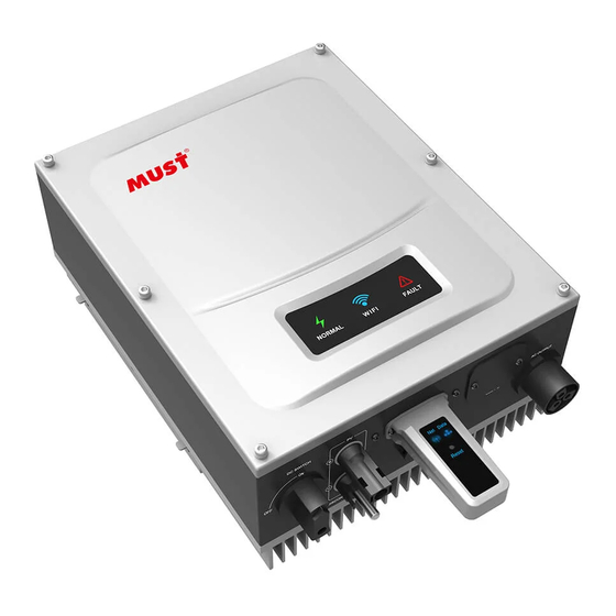
WiFI Description Position PV Input DC switch AC Output RS 485 WiFI The PH5000-T series inverter can choose whether to bring a DC switch depending on customers' need. information Symbol on the inverter Symbol Description Explanation Inverter status symbol Indicates inverter operation status... - Page 10 3.2 Inverter label The inverter can be identified by the label on the left side of inverter. It shows the Products type,the inverter specific features and the parameter on the label. PV Grid Inverter Model Name PH50-***T DC max. voltage ***V MPPT voltage range **-***V...
-
Page 11: Unpacking And Inspection
If you want to storage the inverter in the warehouse, Please select a suitable place to storage. The inverter must be stored in original package and please keep stored in a dry environment The storage temperature should be always between -25 C and +60 C. And the storage relative humidity should be always between 0 and 95%.(Recommend storage environment) - Page 12 Blasting screws 4PCS Output terminals 1PCS Certificate 1PCS Manual 1PCS Wi-Fi Plug14 Quick Installation 1PCS Guideline 4.2 Tools Tool Model Function Hammer drill To drill holes on the wall Recommend drill dia. Remove PV terminal Removal tool Wire stripper Strip wire Turn the screw to connect rear Wrench panel with inverter...
- Page 13 The inverter must only be operated with PV generator. Do not connect any other source to it. Both AC and DC voltage sources are terminated inside the PV Inverter. Please disconnect these circuits before servicing.
- Page 14 This is guidance for installer to choose a suitable installation location, to avoid potential damages to device and operators. The installation location must be suitable for the inverter's weight and dimensions for a long period time. Select the installation location so that the status display can be easily viewed.
- Page 15 3 0 0 Ambient dimensions of series inverters There must be sufficient clearance between the individual inverters to ensure that the cooling air of the adjacent inverter is not taken in. If necessary, increase the clearance spaces and make sure there is enough fresh air supply to ensure sufficient cooling of the inverters.
- Page 16 Please make sure the inverter is installed at the right place.The inverter can’t install close to trunk. Fig4.6 4.5 Installation the Inverter 4.5.1 Mounting Expansion Bolt In order to avoid electrical shock or other injury, inspect existing electronic or plumbing installations before drilling holes. danger To mount the inverter on the wall, we should mount expansion bolt to the wall firmly first.
-
Page 17: Electrical Connection
300mA. You must install a separate three-phase circuit-breaker or other load disconnection unit for each inverter in order to ensure that the inverter can be safely disconnected under load. We suggest you choose the AC breaker rating current in this table:... - Page 18 The AC wiring steps: 1. The grid connection is contains using 5 conductors (L1,L2,L3, N, and PE). 2. Remove the parts of the AC connection plug from the accessory bag. Prepare the pressure screw, sealing ring, threaded sleeve over the AC cable. socket element threaded sleeve sealing ring...
- Page 19 For installation countries falling within the scope of validity of IEC standard 62109, you must install the protective conductor on the AC terminal with a conductor cross-section of at least 10 mm²...
- Page 20 If the inverter is not equipped with a DC switch but this is mandatory in the country of installation, install an external DC switch. The following limit values at the DC input of the inverter must not be exceeded: Max.current input A Max.current input...
-
Page 21: Commissioning
TN-C-S Transformer Transformer Transformer Transformer PH5000-T PH5000-T PH5000-T PH5000-T Note: For TT grid structure , RMS voltage between neutral wire and earth wire must be less than 20V. 6.Commissioning 6.1 LED display Error display Operation normal (Red) (Green) WiFi communication (Blue)... - Page 22 6.2 WIFI Communication Connection Please refer to the Wi-Fi Plug14 Quick Installation Guideline. 6.3 RS485 Cable Connection Rs485 cable connection PIN 1,2 RS485+ PIN 5,7 RS485- PIN 3,4,6,8 Shielding layer or no connection Definitions of RS485 PLUG(standard) as follows PIN 1,2 RS485+ PIN 5,7 RS485-...
- Page 23 2. Slightly loosen the swivel nut,remove the filler-plug from the M20 cable gland. 3. Make the cable through the hole of cable gland and put the cable into the Rs485 terminals, fix all cable with screwdriver(‘1’and‘2’ to ‘RS485+’,‘5’and‘7’ to ‘RS485-’,‘3’ ‘4’ ‘6’ ‘8’to the shielding layer or no connection.)The type of cable is recommended as STP, FTP, ASTP.
-
Page 24: Start-Up And Shut Down The Inverter
7.Start-Up and shut down the inverter 7.1 Start-Up the inverter 1. Connect the AC breaker of the inverter. 2. Turn on the dc switch, and the inverter will start automatically when the input voltage is higher than 200V. 7.2 Turn-off the Inverter Do not disconnect the DC connectors under load. - Page 25 Error message Description Suggestion 1.Check AC wiring, especially the ground wire No utility grid connected or utility NO Utility 2.Contact the installation contractor grid power failure. or supplier 1.Restart inverter. Inverter 2.If error message still exists, contact NTC error temperature fault the installation contractor or supplier.
-
Page 26: Decommissioning
If possible, always pack the inverter in its original carton and secure it with tension belts. If it is no longer available, you can also use an equivalent carton. The box must be capable of being closed completely and made to support both the weight and the size of the inverter. - Page 27 Output (AC) Rated AC output power 7000W 8000W 9000W 10000W 11000W 12000W 13000W 15000W 7700VA 8800VA 9900VA 11000VA 12100VA 13200VA 14300VA 16500VA Max.AC apparent power Max.output current 11.1A 12.7A 14.3A 15.9A 17.5A 20.6A 23.8A Nominal AC Voltage 230V/400V AC Voltage range 184Vac-300Vac 50±5Hz AC grid frequency range...
- Page 28 General Data、Features 500*428*200 Dimension(W/H/D)(mm) weight (kg) Operation temperature -25℃-+60℃ with derating above 45℃ range ≤35dB(A) Noise emission(typical) Altitude 3000m <1W Self-consumption night transformerless Topology Cooling concept Natural Environmental Ip65 protection Rating Relative humidity 100% Features AC connection connector Display Interfaces:USB/WI-FI/ YES/YES /Opt/YES GPRS/ RS485 Standard 5 years/10 years(opt.)
-
Page 29: Pv System Installation
12.PV system installation Installation with multiple inverters on three phase system (A) Single inverter PV array Inverter Breaker Fuse Energy meter Fuse (B) Multi inverter Energy meter Breaker -26-... -
Page 30: Contact
13 Contact If you have technical problems about our products, contact the installation contractor or supplier . We need the following information in order to provide you with the necessary assistance: Inverter type Inverter error messages Inverter LED display Type and number of PV modules connected Optional equipment -27-... - Page 32 PV Grid Inverter 420-00369-00...
Need help?
Do you have a question about the PH5000-T Series and is the answer not in the manual?
Questions and answers
What is normal operating temperature and its maximum limit Ph50.10000TM grid tied invertor
The normal operating temperature range for the Must PH5000-T Series grid-tied inverter is -25℃ to +60℃, with a maximum limit of +60℃.
This answer is automatically generated