Advertisement
Quick Links
Quick Start Install Guide
Easy Step-by-Step Instructions for Removing and Installing SoftPro Salt
Based Water Softeners
Congratulations on your purchase of your new SoftPro Water Softener System.
Below are the installation instructions to get you up and running in no time. We highly
recommend that you follow along in our simple installation videos.
Typical Install Times:
● 3 Hours for a Handyman/ Plumber
● 4 Hours for DIY
Tools Required:
● Flathead Screwdriver
● Phillips Head Screwdriver
● Tongue-and-Groove Pliers (ie. Channellock)
● Adjustable Wrench
● Pipe Cutter
Additional Parts Required:
● Teflon Tape
● ½" ID Teflon Tubing ( length to your drain or drain pipe)
● ½" Hose Clamp
● Additional Pipe Fittings for Rigid Drain Pipe (optional)
● For PVC Pipe:
○ PVC Primer and Glue
● For Copper, PEX, and CPVC pipe:
QualityWaterTreatment.com
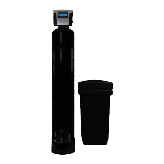
SOFTPRO ELITE SYSTEM
Salt Based
CITY WATER
Advertisement

Related Manuals for Quality Water Treatment SOFTPRO ELITE


Summary of Contents for Quality Water Treatment SOFTPRO ELITE
- Page 1 Quick Start Install Guide Easy Step-by-Step Instructions for Removing and Installing SoftPro Salt Based Water Softeners SOFTPRO ELITE SYSTEM Salt Based CITY WATER Congratulations on your purchase of your new SoftPro Water Softener System. Below are the installation instructions to get you up and running in no time. We highly recommend that you follow along in our simple installation videos.
- Page 2 I NSTALL GUIDE v 20.4 ○ Quick Connect Fittings (ie. Optional Quick-connect Kit/ Hose or SharkBite fittings) Guides: 1) Unpacking and Inspecting Your New System 2) Removing an Old, Existing Water Softener System 3) Installing Your New SoftPro Water Softener System Step-by-Step Install Video ...
- Page 3 I NSTALL GUIDE v 20.4 ● After unpacking, what if there is damage to the valve, tank or other equipment? We got you. If you find visual damage to any of the parts, please take pictures and/or video of the damage. Then please immediately send us the images/ video, and we will get parts shipped to you.
- Page 4 I NSTALL GUIDE v 20.4 a. Carbon Filter Tank Note: The tank comes pre-loaded with carbon media. b. Neoprene Jacket c. Upflow Head d. Upper Basket e. Bypass Valve 2 x 1” Connectors Optional - Chlorine Removal KDF-55. If purchased, the Chlorine Removal KDF-55 will be pre-installed inside the mineral tank.
- Page 5 I NSTALL GUIDE v 20.4 8. Optional - Whole House Carbon Filter Package below. Now that you have verified that you have all components listed let’s get started on installing your new softener.
- Page 6 I NSTALL GUIDE v 20.4 For Removal of Old Softener System If applicable, the following guide is typical of how many common water softeners are removed. If you find that your existing setup is unconventional, please take pictures and videos to send to our support team to review.
- Page 7 I NSTALL GUIDE v 20.4 Step 3) Open the nearest cold water faucet to help empty the remaining water in the pipes. We don’t want a flood. H elpful tip: Open a cold water faucet in the home, Removing a shower head because it is up high will create a good vacuum so pipes can drain faster and better.
- Page 8 I NSTALL GUIDE v 20.4 If the bypass valve includes the inlet and outlet valves, then close both the inlet and outlet valves. If the bypass valve has one stem, close the plunger into the stem or pull handle as shown in the first image.
- Page 9 I NSTALL GUIDE v 20.4 6) D isconnect inlet and outlet lines. Remove the holding clips at the water softener inlet and outlet. Disconnect the water softener from the water pipes. If there are no clips, then cut the water line pipe as it enters the water softener. Use the appropriate cutting tool for the different types of pipes (copper, PVC, PEX, CPVC, etc.)
- Page 10 I NSTALL GUIDE v 20.4 Step 7) D isconnect brine line. Disconnect the brine line from the side of the softener valve. Step 8) R emove the old brine tank and mineral tank. Step 9) Clear and clean the area for your new SoftPro Water Softener System. You are now ready to install your new SoftPro Water Softener System.
- Page 11 I NSTALL GUIDE v 20.4...
- Page 12 I NSTALL GUIDE v 20.4 Step-by-Step Install Video We highly recommend that everyone refer to our install videos. Makes it easy and fast! Step-by-Step Install Video: QualityWaterTreatment.com/Install Installing your New Water Softener Installing your new SoftPro Water Softener is straightforward. The following step-by-step guide accompanied by our install videos ( QualityWaterTreatment.com/Install ), will get your new system up and running for you to enjoy fantastic soft water.
- Page 13 I NSTALL GUIDE v 20.4 A ssemble your water softener: Step 1 ) Setup your brine tank. a) Remove the grid plate and legs from the brine tank, and snap the legs into the bottom of the grid plate. You will hear a “click” sound after securing each leg. ( Note...
- Page 14 I NSTALL GUIDE v 20.4 b) Place the grid plate with legs facing downward into the bottom of the brine tank and push down firmly. Align the brine well cylinder to the small brine line hole near the top of the brine tank.
- Page 15 I NSTALL GUIDE v 20.4 d) Connect the brine line to the float in the brine well cylinder. Run the brine line tubing through the small hole near top of the brine tank. iii) Attach the plastic nut and insert the plastic sleeve into the tubing end. Only hand tighten the brine line nut to the float assembly.
- Page 16 I NSTALL GUIDE v 20.4 Step 2) Setup the optional Whole House Carbon Filter*. (*If not purchased, skip to the next step.) Note: T he Whole House Carbon Filter is p re-loaded with carbon media. Install the neoprene jacket. Wrap the black neoprene jacket around the carbon filter tank.
- Page 17 I NSTALL GUIDE v 20.4 d) Lower upflow head with upper basket attached over the distributor tube located in the carbon filter tank. Only hand tighten the head onto the tank. Note: D o not use lubricants or Teflon tape. e) Install the bypass valve to the upflow head.
- Page 18 I NSTALL GUIDE v 20.4 f) Attach the two connection fittings onto the bypass valve. g) Plumb the main water supply line to the Inlet side of the carbon filter. Note: The “arrow” pointing away from the valve is the INLET side. Note:...
- Page 19 I NSTALL GUIDE v 20.4 i) Install a hose bib. Install a “T” fitting and a hose bib on the OUTLET side of the carbon filter. a) Note: This will be used to initially clean out any carbon dust from your carbon filter tank prior to the water entering your water softener.
- Page 20 I NSTALL GUIDE v 20.4 Step 3) Install the neoprene jacket. Wrap the black neoprene jacket around the carbon filter tank. Zip it up and pull the bottom of the jacket down to remove wrinkles. Step 4) Unscrew media spill cap from the top of the tank . Step 5) Attach upper basket to bottom of control valve by twisting into place, gently pull on basket to make sure it is secure...
- Page 21 I NSTALL GUIDE v 20.4 Step 6) Add additional resin media (only to 80k or larger), if required.* (Otherwise skip to the next step.) *If over a 80,000 or larger grain capacity softener, then add the appropriate media/ resin we supplied you with to the top of the mineral tank.
- Page 22 I NSTALL GUIDE v 20.4 Step 7) Attach the control valve to the mineral tank. a) Place the valve onto the top of the mineral tank. b) Guide the bottom of the basket to insert the distributor riser tube (“D-Tube” or Riser Tube) that is located inside the tank.
- Page 23 I NSTALL GUIDE v 20.4 WARNING: B e careful not to pinch or wind the electrical cord in the threads/ valve and tank connection. Step 8) Install the bypass valve to the control valve. a) Remove the two red clips from the rear of the SoftPro control valve.
- Page 24 I NSTALL GUIDE v 20.4 b) Press the bypass valve into the rear of the Softpro control valve. c) Reinstall the red clips. Gently tug on the clips to make sure they are locked into place.
- Page 25 I NSTALL GUIDE v 20.4 Step 9) Wrap Teflon tape onto both elbow fittings. WARNING: USE ONLY TEFLON TAPE. Do not use pipe dope or plumbers putty. This can damage the plastic fittings. Step 10) Connect the plumbing fittings to the bypass valve. See Quick-Connect Kit or standard connection step...
- Page 26 I NSTALL GUIDE v 20.4 Attach the appropriate water lines to appropriate sides of the bypass valve. The water supply line connects to the INLET side with the b lue t ag. The feed/ soft water line connects to the OUTLET side with the r ed tag.
- Page 27 I NSTALL GUIDE v 20.4 Step 11) Connect the brine line to the control valve.
- Page 28 I NSTALL GUIDE v 20.4 Insert the plastic sleeve ( this can be found on the thin wire holding the vanilla tag on the brine line elbow) and hand tighten the brine line nut to the elbow fitting.
- Page 29 I NSTALL GUIDE v 20.4 Step 12) Connect the drain line to the control valve. WARNING: D o not remove the drain line elbow or fitting from the rear of the control valve. ( This fitting includes the drain line flow control. If removed, the system will not work properly and the resin will drain out when the system regenerates.
- Page 30 I NSTALL GUIDE v 20.4 c) Run the drain line to an appropriate drain area. d) WARNING: Do not install the drain line more than 3 feet above the control valve.Note: Waste connections or drain outlet shall be designed and constructed to provide for connection to the sanitary waste system through an air-gap of 2 pipe diameters or 1 inch (22 mm) whichever is larger.
- Page 31 I NSTALL GUIDE v 20.4 Rigid Drain Line Pipe Option: To use a rigid pipe (PVC, CPVC etc.), attach the rigid pipe to the open end of the vinyl tubing. Note: Vinyl tubing must be connected to the control valve, and then the rigid pipe can be connected to the open end of the vinyl tubing using a ½”...
- Page 32 I NSTALL GUIDE v 20.4 Step 13) S hut-off the main water supply. Close the water main shut-off valve to the home. It’s usually located in the front of the property. If you have a shut off as water enters home you can also shut it off there. a) Verify and label the water supply and feed lines for the water softener.
- Page 33 I NSTALL GUIDE v 20.4 c) If a soft water loop does not exist: then you will need to install a loop from the main water supply line prior to entering your home or have a professional install one. Step 14) For the optional Whole House Carbon Filter Installation, if applicable, complete the carbon filter connection to the water softener.
- Page 34 I NSTALL GUIDE v 20.4 a) Plumb the Carbon Filter Outlet side to the water softener INLET side. (a) Plumb the line from the carbon filter hose bib “T” fitting to the water softener. b) Verify that the carbon bypass valve is in the bypass position Step 15) Connect the water softener to the plumbing.
- Page 35 I NSTALL GUIDE v 20.4 The B lue l abel is marked as inlet and the R ed L abel is marked as outlet. Optional Step) Install soft water hose bib:. A soft water hose bib located near the water softener can aid in convenient water testing and allow access to soft water (great for washing cars and windows, etc.).
- Page 36 I NSTALL GUIDE v 20.4 a) Verify that the water softener valve is in the bypass position. Step 16) Turning the water back on. a) SLOWLY turn on your water main. b) Turn on a faucet in the home or attach a garden hose to the soft water hose bib and turn it on ( recommended) c) Run the water until it shows clear.
- Page 37 I NSTALL GUIDE v 20.4 Once the water runs clear into the container, turn off the faucet. Step 17) For Whole House Carbon Filter Installation, see below for initially cleaning the carbon filter tank. (Skip to the next step if not applicable.) a) SLOWLY turn open the INLET side of the carbon filter bypass valve (opens clockwise) until the carbon filter tank fills with water.
- Page 38 I NSTALL GUIDE v 20.4 Step 18) Initial cleaning of the softener mineral tank. f) SLOWLY turn open the INLET side of the softener bypass valve (opens clockwise) until the mineral tank fills with water. Once the tank is full, the water will stop running. g) SLOWLY ...
- Page 39 I NSTALL GUIDE v 20.4 Note: Check the water inside the container for clarity. Note: ● Manual regeneration is NOT required. ● Resin media has been previously pre-charged and ready for use. Step 19) Add 2 gallons of water to the brine tank. Step 20) Add salt to the brine tank.
- Page 40 I NSTALL GUIDE v 20.4 Step 21) Plug your control valve power supply into the electrical outlet. Your new SoftPro Water Softener is complete and ready for programming. Programming Your New SoftPro Valve We highly recommend that everyone refer to our programming videos. Makes it easy and fast! Step-by-Step Valve Programming Video: QualityWaterTreatment.com/Install...
- Page 41 I NSTALL GUIDE v 20.4 Does this system backwash after each regeneration? No. This system does not backwash after every regeneration. This efficient system backwashes every 8 to 10 regenerations.( we have you set it to 5 or 6 in the programming video).
- Page 42 I NSTALL GUIDE v 20.4 Cold water should be almost immediate in the home, hot water can take up to a week if using a non tankless water heater. You can drain the tank to make it go by faster if you choose.
- Page 43 I NSTALL GUIDE v 20.4 Help@QualityWaterTreatment.com...
Need help?
Do you have a question about the SOFTPRO ELITE and is the answer not in the manual?
Questions and answers