Table of Contents
Advertisement
Advertisement
Table of Contents

Summary of Contents for Lang Radar Touch RT500
- Page 1 Manual Version 3.4...
-
Page 2: Table Of Contents
5.1 Changing the IP address of your computer................22 5.2 Changing the IP address of the measurement device............... 24 5.3 How to ping the radarTOUCH....................... 25 5.4 Solving Problems .......................... 27 5.5 Pin Assignment ..........................27 5.6 Technical Data ..........................28 T. Schwirten LANG AG 14.10.10 Page 2... -
Page 3: Radartouch Contents
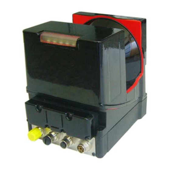
- Safety wire RT500 standard mounting system (Figure 7) with: - Two screws M5 * 45 - Two screws M5 * 50 - Safety wire Figure 1 RT500 measurement device (Colour might vary!) T. Schwirten LANG AG 14.10.10 Page 3... - Page 4 Manual radarTOUCH Version 3.4 Figure 2 Power supply cable and mains adapter Figure 3 Ethernet cable with 5Pin XLR female to Ethernet adapter Figure 4 USB Dongle containing the radarTOUCH Software T. Schwirten LANG AG 14.10.10 Page 4...
- Page 5 Version 3.4 Figure 5 RT500 Deluxe mounting system Figure 6 Accessories deluxe mounting system Figure 7 RT500 Standard mounting system (in case of renting) Consists of: Truss mounting (left) and ceiling mounting (right) T. Schwirten LANG AG 14.10.10 Page 5...
-
Page 6: About The Radartouch
Figure 9 Using the radarTOUCH in front of a rear projection T. Schwirten LANG AG 14.10.10 Page 6... - Page 7 Figure 11 shows the minimum diffuse reflection in percent compared to the distance that an obstacle needs to be detected. For these values the size of the obstacle has to be big enough and is a given fact in the diagram. T. Schwirten LANG AG 14.10.10 Page 7...
- Page 8 These diagrams should only provide an approximate idea of the object sizes that might be considered when integrating a radarTOUCH and are usually more pessimistic than the reality. In the end, only practical tests can deliver reliable answers. T. Schwirten LANG AG 14.10.10 Page 8...
-
Page 9: Installing And Connecting The Radartouch
(the longer 50mm screws belong to the top of the measurement device, this is where the cables are connected) (see also Figure 16). The mechanical adjustments require some practice but then it is possible to adjust it rather close to any surface (~2.0cm). T. Schwirten LANG AG 14.10.10 Page 9... - Page 10 Z-Direction Tilt Figure 14 Adjustment features Deluxe Mounting System (Top view) Measurement Ceiling device Figure 15 Deluxe Mounting System (Side view) M5x45 M5x50 Figure 16 Measurement device attached to the deluxe mounting system T. Schwirten LANG AG 14.10.10 Page 10...
-
Page 11: Standard Mounting System
Rotation angle measurement device compared to the active area (should be 0°) but only in a small range Tilt Rotation Figure 17 Adjustments for standard mounting system Rotation Figure 18 Screws for rotating adjustment T. Schwirten LANG AG 14.10.10 Page 11... -
Page 12: Connection
(Please refer to chapter “5.1 Changing the IP address of your computer” learn how to » change the IP address) T. Schwirten LANG AG 14.10.10 Page 12... -
Page 13: The Radartouch Software
The slider “Vertical offset” and “Horizontal offset” adjust the vertical and horizontal position of the active area. With the Smoother slider you can adjust the strength of a de-noising algorithm. If it is set to the value 1, it is set to bypass. T. Schwirten LANG AG 14.10.10 Page 13... - Page 14 PreViz and in the drop down box. The ID is always -1. You can adjust all parameters like the way it is done with all the other active areas. If you check the “Enable” box, the mouse will be controlled. T. Schwirten LANG AG 14.10.10 Page 14...
-
Page 15: The Previz
Draws every 10 measurements the number on the angular element » g: Draws start and end points of the obstacles » Figure 22 PreViz with one active area Figure 23 PreViz with two active areas T. Schwirten LANG AG 14.10.10 Page 15... -
Page 16: Multiblobviz
Figure 24 MultiBlobViz test program The middle of a blob should be the middle of you finger, then the active area was set up correctly. Check the center and also the boarders of your screen. T. Schwirten LANG AG 14.10.10 Page 16... -
Page 17: The Info-Window
Shall the left button be clicked and released when entering the active area with an obstacle? Or shall it work like a drag and drop function which keeps the button clicked as long as the obstacle is detected? T. Schwirten LANG AG 14.10.10 Page 17... -
Page 18: Open Sound Control (Osc): Tuio
→ IDs of all detected obstacles This is sent once for one measurement and includes all active detected obstacles. For more detailed information please have a look at http://www.tuio.org/?tuio10. Everything needed is described there. T. Schwirten LANG AG 14.10.10 Page 18... -
Page 19: Xml Files
<hFlip>false</hFlip> <vFlip>false</vFlip> <interpreterList> <activeArea> <activeHeight>600</activeHeight> <activeWidth>1000</activeWidth> <colour>0</colour> <colour>0</colour> <colour>255</colour> <HOffset>0</HOffset> <VOffset>50</VOffset> </activeArea> <smootherLevel>1</smootherLevel> <port>3333</port> <inetAdress>192.168.60.11</inetAdress> <uniqueID>0</uniqueID> </interpreterList> <selectedInterpreterInComB>0</selectedInterpreterInComB> <mouseSettings> <activeArea> <activeHeight>200</activeHeight> <activeWidth>300</activeWidth> <colour>255</colour> <colour>0</colour> <colour>0</colour> <HOffset>0</HOffset> <VOffset>50</VOffset> </activeArea> <smootherLevel>1</smootherLevel> <uniqueID>-1</uniqueID> <mouseEnabled>false</mouseEnabled> </mouseSettings> </ns2:settings T. Schwirten LANG AG 14.10.10 Page 19... -
Page 20: Configuration File
== 2 This version does a single click and a double click depending on the time between two new obstacles. If the system detects two obstacles, it keeps the left mouse button clicked. T. Schwirten LANG AG 14.10.10 Page 20... - Page 21 If both parameters are set to zero, the system uses the normal algorithm for detecting obstacles. If you choose to use them, the system uses a different algorithm that has its strengths performing some sort of a blob reduction. trackingSettings You should not change anything here! T. Schwirten LANG AG 14.10.10 Page 21...
-
Page 22: Appendix
Ethernet cable to the computer. » Go to „My Network Places (right mouse button) > Properties„ » Make sure that this LAN-connection is the connection to the radarTOUCH and open its Properties: T. Schwirten LANG AG 14.10.10 Page 22... - Page 23 » Choose the TCP internet protocol and click on Properties » Now you can give your computer a static IP address or change it: » Confirm your settings and close the Network Places T. Schwirten LANG AG 14.10.10 Page 23...
-
Page 24: Changing The Ip Address Of The Measurement Device
If you change the IP address of the device, you also have to change the IP in the radarTOUCH software. For this, please refer to chapter 4.3.2 Configuration file. Figure 26 radarTOUCH IP Changer GUI Figure 27 Confirm dialog Figure 28 Dialog after setting the new IP T. Schwirten LANG AG 14.10.10 Page 24... -
Page 25: How To Ping The Radartouch
The default IP address of the radarTOUCH is 192.168.60.3 » Now this IP will be pinged four times and if the ethernet connection is available there will be a response like it is shown in the following picture: T. Schwirten LANG AG 14.10.10 Page 25... - Page 26 If the IP address you want to ping is wrong, the following response will appear: » In both of this cases please check the connection and the IP of your PC. (Please refer to chapter “5.1 Changing the IP address of your computer”) T. Schwirten LANG AG 14.10.10 Page 26...
-
Page 27: Solving Problems
Pin 1 Pin 1 Green/white Yellow Pin 2 Pin 2 Green Orange CAT 5 radar ↔ Pin 3 Pin 3 Cable TOUCH Pin 4 Pin 4 Red/white White Pin 5 Pin 5 Blue T. Schwirten LANG AG 14.10.10 Page 27... -
Page 28: Technical Data
4 connectors (to be plugged from above) Environmental data Ambient temp. 0°C…+50°C/-20°C…+50°C (operation/storage) -20…+50°C/-20°C…+50°C (RTouch-500plus – with heater) VDE safety class II, all-insulated Laser class 1 (acc. To EN 60825-1) Protection class IP 65 Standards applied IEC 60947-5-2 T. Schwirten LANG AG 14.10.10 Page 28...
Need help?
Do you have a question about the Radar Touch RT500 and is the answer not in the manual?
Questions and answers