
Related Manuals for Perma ECOSY 5


Summary of Contents for Perma ECOSY 5
- Page 1 Translation of the Original Operating Instructions perma ECOSY 5 The Expert in Lubrication Solutions...
-
Page 2: Validity Of The Operating Manual And Information On This Publication
Exception: When triggering an “additional discharge”, all outlets are supplied with the same amount of lubricant. Without the specific approval of perma-tec GmbH & Co. KG, no part of this documentation may be copied or made available to third parties. -
Page 3: Table Of Contents
Table of contents ..................3 Various ..................5 About this Operating Manual ............5 Versions and Scope of Delivery ............6 The Oil Lubrication System perma ECOSY 5 ........7 Legal Requirements ................. 8 Safety Instructions ............... 9 Staff Responsible for Safety ............. 9 General Safety Instructions ............. - Page 4 Test Run for All Outlets ..............45 Discharge Amount From Pump to Distributor Dependent on Counter Pressure and Temperature ....47 Connection of perma ECOSY 5 ........... 48 10.1 The Mains Supply (85 - 240 V AC) - Connection Via Plug-in Connector A ..........48 10.2...
-
Page 5: Various
About this Operating Manual • This operating manual is intended for the safe operation of the automatic lubrication system perma ECOSY 5. It contains safety instructions which must be strictly adhered to. • Everyone who works on or with the lubrication system must have access to this operating manual during their shift. -
Page 6: Versions And Scope Of Delivery
Versions and Scope of Delivery • perma ECOSY 5, its attached parts and oil composition are individually put together according to customer requirements. • The lubrication system is delivered with an oil-filled pump. The reservoir is empty. The oil must be ordered separately and will be delivered in a separate container. -
Page 7: The Oil Lubrication System Perma Ecosy 5
The Oil Lubrication System perma ECOSY 5 1.3.1 Markings • The perma ECOSY 5 lubrication system is clearly marked with a label on the pump. • CE mark on the reservoir • Manufacturer: perma-tec GmbH & Co. KG Hammelburger Straße 21... -
Page 8: Legal Requirements
• perma-tec GmbH & Co. KG can not be held liable for damages and malfunctions caused by: … violation and / or non-observance of the safety instructions …... -
Page 9: Safety Instructions
• Ensure that the relevant safety and operating instructions are observed when the lubrication system is installed or serviced on machines or in factories (e.g. stop the machine)! © 2020 - perma-tec www.perma-tec.com GmbH & Co. KG... -
Page 10: Safety Instructions For Perma Ecosy 5
• Operate the lubrication system only when it is in perfect condition. • Retrofitting, changing, or reconstructing the lubrication system is not allowed. • If you are planning to modify the lubrication system, perma-tec must be consulted first. • The lubrication system must be filled with the correct oil. It must... -
Page 11: Safety When Handling Lubricants
• Prevent lubricant from getting into soil or sewer system! • For the disposal of lubricants, follow the individual waste disposal regulations in your country! • Only use genuine spare-parts from perma-tec! Safety in Case of Fire • Personal protection comes before material protection! •... -
Page 12: Technical Data
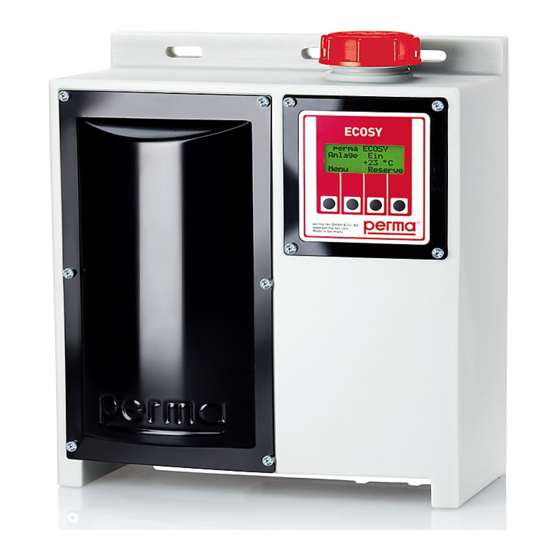
Technical Data Product Characteristics 3.1.1 Design perma ECOSY 5 basically consists of (Fig. 3-1, 3-2): 1 Housing with mounting holes 2 Filling hole with filter and screw cap 3 Display and control unit 4 Cover of the pump compartment 5 Pump and distributor unit... - Page 13 Languages (Display) de, en, fr, cs, it, es, nl (illuminated) NOTE All options exist; usable functions depend on connections and chosen accessories (see chapter 10 “Connection”, 15.1 “Accessories” and 15.2 “Spare Parts”). © 2020 - perma-tec www.perma-tec.com GmbH & Co. KG...
- Page 14 Clearance needed for canister and filling de- vice used for refilling Fig. 3-3: External dimensions in mm NOTE If there is not enough space to refill the reservoir using a canister, use a pump (with filter) and a clean tube. perma ECOSY...
-
Page 15: Operating Conditions
• Prior to doing work where arcs might occure, protect any endangered tubes and ECOSY 5 parts! 3.2.1 Temperatures • Range: -20 °C to +60 °C (-4 °F to +140 °F) with suitable oils. -
Page 16: Storage
3.2.3 Lubricating Oils Oil for use in lubrication system perma ECOSY 5 cannot contain any solids. The viscosity class of the oil must be 65 to 2000 mm²/s at 40 °C. You may also download data sheets of lubricants supplied by perma-tec from perma-tec’s web page (www.perma-tec.com) or... -
Page 17: Mounting
3-3 and fix the system with screws. Finger tighten screws and add a quarter turn. • Remove cover of pump compartment (4, Fig. 3-1). • Connect perma ECOSY 5 outlets with the lubrication point using tube or hose connections. Outlet number is imprinted on the distributor housing. -
Page 18: Connection To Power Supply
• Install control sensor. Ensure that connection cable is secure. • Connect control sensor according to chapter 10.2.3. • Check: turn perma ECOSY 5 on and hold a piece of metal to the sensing end of the control sensor. If the control sensor was attached correctly, an indication light will light up on the back of the control sensor. -
Page 19: Operation
Operation Preparation Before starting perma ECOSY 5 for the first time, fill the reservoir until the display no longer shows “RESERVE” (see chapter 7). NOTE If there is not enough space to refill the reservoir using a container, use a pump (with filter) and a clean tube. -
Page 20: Check Prior To Operation
Inspection: at regular intervals, depending on discharge settings. Recommendation: once a month. • perma ECOSY 5 can be linked to a superior control system (see chapter 10 “Connection of perma ECOSY 5”). The fill level will then be monitored electronically and necessary refills will automatically be signalled via the PLC. -
Page 21: Refilling The Reservoir
CAUTION • No smoking, no open flames within a radius of 15 m (45 ft)! • Ensure that no water or foreign liquids enter perma ECOSY 5 or the lubrication point. Refills may only be carried out in dry areas or with effective protective measures! •... -
Page 22: Perma Ecosy 5 Settings
ECOSY 5 Settings CAUTION Prior to operation, check setting of discharge volume and adjust it according to your particular application! Control Panel Settings (Edit-Mode) The following can be set at the control panel: • Parameters Manufacturer setting • Discharge volume per outlet... - Page 23 Setting of perma ECOSY 5 is only possible in the Edit-Mode. All settings that are marked with {PIN} require the entry of the PIN (Personal Identification Number). The PIN is pre-set to “000” by the manufacturer. When you first start, you can change the settings by just confirming the pre-set PIN with “OK”...
-
Page 24: Function Indication
Function Indication The status of the perma ECOSY 5 is shown on the display with “ON” or “OFF”. If operating mode “TIME” was selected, the perma ECOSY 5 is always “ON”. With “SENSOR” or “CONTROL”, the lubrication system is only “ON”... - Page 25 This discharge impulse, and any additional ones, are saved in memory. Once the temperature rises again above the limit, the system will carry out all saved discharge impulses. © 2020 - perma-tec www.perma-tec.com GmbH & Co. KG...
-
Page 26: Setting Of Parameters
Press “>>” until the arrow on the screen appears next to the required << >> Esc outlet. Parameter In this example, the settings of outlet 3 Vol. outlet 3 will be changed. Vol. outlet 4 << >> Esc Press “OK”. perma ECOSY... - Page 27 0500 ml/1000h Every time you press “ESC”, you will Edit reach a higher menu level. Tightly seal all inactive outlets with a plug (see menu “parameter” outlets set to 0 discharge volume). © 2020 - perma-tec www.perma-tec.com GmbH & Co. KG...
-
Page 28: Setting Of Temperature Limit
8.3.2 Setting of Temperature Limit perma ECOSY 5 is already shut down if the set temperature limit is reached. This means that if -5 °C (23 °F) was set, the discharging process will already be interrupted at -5 °C (23 °F) until the tem- perature rises above this set value again. - Page 29 -15 °C. Temp. shut off -10 °C -15 °C Save the changed value with “OK”. >> Press “ESC” as many times as necessary until you get to the main menu [B1]. © 2020 - perma-tec www.perma-tec.com GmbH & Co. KG...
-
Page 30: System Configuration
NOTE • Discharges can be triggered by external control signals. Such signals do not come from the ECOSY 5 software, but from ex- ternal sensors, a primary control, or a manual entry. • Internal signals will convert the external signals into lubricant discharges. - Page 31 8.4.1.1 Discharge Process in Operating Mode TIME • In operating mode TIME, the ECOSY 5 runs autonomously (purely on a 24-hour basis) and calculates the discharge point based on the discharge volumes selected / set. • The objective is to convey the selected volume to the lube point in equal amounts each time (programming basis is 1000 h).
- Page 32 8.4.1.2 Discharge Process in Operating Mode CONTROL • In operating mode CONTROL, the ECOSY 5 reacts to the system status of the machine to be lubricated. Only the machine‘s “ON” time is taken into consideration. Downtimes are not factored in for the discharge. To this end, the machine must send a signal (permanent signal, 24 V) to switch the ECOSY 5 “ON”...
- Page 33 8.4.1.3 Discharge Process in Operating Mode SENSOR • In operating mode SENSOR, the ECOSY 5 reacts to the system status of the machine to be lubricated. Only the machine‘s “ON” time is taken into consideration. Downtimes are not factored in for the discharge.
-
Page 34: Setting Of Operating Mode
“>>”. << >> Esc Menu Configuration Test run Press “OK”. << >> Esc Configuration “Operating mode” is already selected. Operating mode Temp. unit Press “OK” (after selected PIN was confirmed according to chapter 8.4.6). << >> Esc perma ECOSY... - Page 35 >> Esc are not saved. Configuration After acknowledging with “OK”, Operating mode press “ESC” as many times as Temp. unit necessary until you get to the << >> Esc main menu. © 2020 - perma-tec www.perma-tec.com GmbH & Co. KG...
-
Page 36: Setting Of Temperature Unit (°C Or °F)
>> Esc Configuration Temp. unit Language Press “OK”. << >> Esc Select the required unit with the Temp. unit arrows “>>” or “<<”. Celsius Fahrenheit The display switches from Celsius << >> Esc to Fahrenheit and back again. perma ECOSY... - Page 37 When the language is changed, the originally set temperature values remain. If required, they must be changed separately. a) Temperature unit b) Temperature shut-off © 2020 - perma-tec www.perma-tec.com GmbH & Co. KG...
-
Page 38: Setting Of Language (Pre-Set To German)
If you press “>>” only 1 time, display shows “Temp. Einheit” (= Temp. unit) << >> Esc Konfiguration Temp. Einheit Press “>>” again and display will Sprache show “Sprache” (= Language) << >> Esc Konfiguration Sprache Kontrast Press “OK”. << >> Esc perma ECOSY... - Page 39 Contrast B30E sary until you get to the main menu. << >> Esc All menus are already in English. ECOSY System +20 °C Display of the main menu in English Menu © 2020 - perma-tec www.perma-tec.com GmbH & Co. KG...
-
Page 40: Adjusting The Contrast
Temp. unit “Temp unit” is displayed B26, 2nd push of button: << >> Esc “Language” is displayed B50, 3rd push of button: B51. “Contrast” is displayed Configuration Temp. unit Language << >> Esc Configuration Language Contrast << >> Esc perma ECOSY... - Page 41 ++ Esc Contrast Press “OK” to save the selected contrast setting. ++ Esc Configuration Contrast Press “ESC” until you reach the main Change PIN menu again. << >> Esc © 2020 - perma-tec www.perma-tec.com GmbH & Co. KG...
-
Page 42: Pin (Personal Identification Number)
8.4.6 PIN (Personal Identification Number) ECOSY 5 settings can only be changed in the Edit-Mode. In order to get to the Edit-Mode, the correct PIN must be entered. For the initial start it is sufficient to confirm the factory set PIN “000” by pressing “OK”. - Page 43 “ESC” several times. The Edit-Mode stays active for about 1 >> minute after the last push of the button. If you want to re-activate the Edit-Mode, you must enter the correct PIN. © 2020 - perma-tec www.perma-tec.com GmbH & Co. KG...
-
Page 44: Carrying Out A Test Run
>> Esc chapter 8.4.6. Test run Press “OK”. Single outlet All outlets “Single outlet” is already selected. << >> Esc Change is not necessary. Single outlet Outlet No. 1 Select the required outlet with “++” or “--”. ++ Esc perma ECOSY... -
Page 45: Test Run For All Outlets
Only activated outlets are supplied with oil, where the programmed discharge is greater than “0” (see chapter 8.3.1 “Setting of Dischar- ge Amount”). ECOSY System +20 °C Press “Menu”. Menu Menu Parameter Configuration Press “>>”. << >> Esc © 2020 - perma-tec www.perma-tec.com GmbH & Co. KG... - Page 46 (see “Error Displays” in chapter 11). All outlets After the discharge, exit menu with Lube on “ESC”. conf. outlets Press “ESC” as many times as necessary << >> Esc until you get to the main menu. perma ECOSY...
-
Page 47: Discharge Amount From Pump To Distributor Dependent On Counter Pressure And Temperature
Discharge Amount From Pump to Distributor Dependent on Counter Pressure and Temperature Discharge amount from pump to distributor of perma ECOSY 5 will be constant, if the temperature is constant. In case of coun- ter pressure from the lubrication point and if the temperature changes, the discharge volume may also change. -
Page 48: Connection Of Perma Ecosy 5
Connection of perma ECOSY 5 All tasks on the control system of the ECOSY 5 must be carried out by qualified staff. NOTE To ensure max. operating safety (e.g. broken wire), perma ECOSY 5 has been fitted with POSITIVE logic at the input side and with NEGATIVE logic at the output side. -
Page 49: The Control Panel - Connection Via Plug-In Connector B
10.2 The Control Panel - Connection Via Plug-in Connector B The perma ECOSY 5 is connected to control systems via the 8-pole plug-in connector. The plug is included with the delivery and must be connected as illustrated in the circuit diagrams. -
Page 50: 10.2.1 Connection Via Relays
• For 24 V DC, the mains supply (plug connection A) MUST NOT be used! • The used 24 V power supply must be sufficiently dimensioned for the operation of perma ECOSY acc. to its power consumption (chapter 3.1.2.). perma ECOSY... -
Page 51: 10.2.3 Connection Of Ecosy Control Sensor
Controls / sensor 24V 1 brown Controls / sensor GND 3 blue Controls / sensor IN 4 black 2 - 4 mm Fig. 10-6: ECOSY Control sensor Fig. 10-7: Range with cable © 2020 - perma-tec www.perma-tec.com GmbH & Co. KG... -
Page 52: Troubleshooting
- Check the set Operating mode. ECOSY 5 displays: Filling level of perma - Refill oil (at least until the “Error reserve ECOSY 5 has fallen below reserve display is no longer min. level” the minimum. indicated), then acknowledge error. - Page 53 (mech. sealed outlets can not be activated). ECOSY 5 displays: Stroke recognition of pump - Send perma ECOSY 5 to “Error pump not defective or defective pump. your local supplier for working” repairs.
-
Page 54: Dismounting The Lubrication System
• Tightly seal containers and secure them against unintentional spilling. • Seal tube ends with plugs or blind plugs. • Tightly seal tube connections on the ECOSY 5 with plugs or blind plugs. • Absorb any spilled oil and completely remove it from the floor. -
Page 55: Dismounting The Ecosy 5
12.2 Dismounting the ECOSY 5 CAUTION Position the ECOSY 5 upright at a safe place so that no oil may spill and the system is protected against damages and overturn- ing (recommendation: place the lubrication system in a leak proof container like a tub)! •... -
Page 56: Disposal
Disposal Help us in protecting the environment and saving resources by recycling valuable raw material. Please follow the individual waste disposal regulations in your country. perma ECOSY... -
Page 57: Accessories For Perma Ecosy 5
Accessories and spare parts must meet the technical requirements! This is always guaranteed with genuine spare parts from perma-tec. We recommend that you contact local suppliers if you are planning to extend your system or to install accessories or spare parts on perma lubrication systems. 15.1 Accessories •... -
Page 58: Maintenance And Service
The filter of the filler neck should be cleaned if it contains any dirt. Send ECOSY 5 to your local supplier for any other maintenance work. For shipment of perma ECOSY 5 to your local supplier, please refer to chapter 12 and 13 for correct dismounting and shipping. -
Page 59: Ec Declaration Of Conformity
EN ISO 12100:2010 (EN 61000-6-2:2005, EN 61000-6-4:2007+A1:2011) Euerdorf, 20 October 2015 Walter Graf, Managing Director Egon Eisenbacher, Technical Management © 2020 - perma-tec www.perma-tec.com GmbH & Co. KG... - Page 60 GmbH & Co. KG Hammelburger Str. 21 97717 EUERDORF DEUTSCHLAND Tel.: +49 9704 609-0 info@perma-tec.com www.perma-tec.com...
Need help?
Do you have a question about the ECOSY 5 and is the answer not in the manual?
Questions and answers