
Related Manuals for DTS 600 Elite


Summary of Contents for DTS 600 Elite
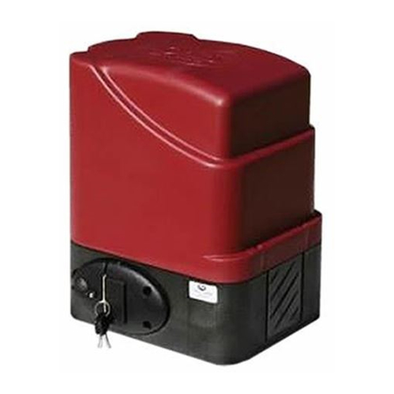
- Page 1 SLIDING GATE MOTOR INSTALLATION MANUAL DTS 600 Elite with SL150 PCB DTS SECURITY P.O.BOX 3399 Base plate-mounting instructions EDENVALE 1610 TELEPHONE 086 1000 387 Spartan +2711 392 5540 (H/O) Pretoria +2712 361 5528 E-EEEE www.dtssecurity.co.za...
-
Page 2: Default Settings
INDEX PAGE Default settings & Error Codes and messages Features Gearbox mounting & Gate motor override How set install the limit switch actuators Power connection & Courtesy light connections External connections Programming (Calibrating the motor) Motor direction setting Auto close, Condo mode, PIRAC mode 7 &... - Page 3 FEATURES: Standard mode. Selectable motor direction change. Auto close facility. (Infra-red beams must be fitted if auto close is activated). Party mode. (Auto close override) Condominium / Free exit loop facility. P.I.R.A.C. (Passive Infra-Red Access Control) facility. Slowdown (Ramp down) facility. Tamper facility, Anti-hijack/Alarm facility.
-
Page 4: Rack Mounting Instructions
Gearbox mounting instructions 1. Fit gearbox over mounting bolts protruding from base plate. 2. Slide gate fully open and closed, insuring pinion gear has approximately 5mm clearance to gate at all times. 3. Fasten gearbox down firmly to base plate using M10 washers and nuts. How to override the gate motor for manual operation 1. -
Page 5: Power Connections
POWER CONNECTIONS High access power supply unit – 220V at motor. ( DTS600, 120VA has a 2 Amp fuse) Connect 220V AC to LEN (Live/Earth/Neutral) connector on side of power supply unit. Black lead from power supply unit gets connected to – ( neg.) HA PSU connection on PCB. Red lead from power supply unit gets connected to + ( pos.) HA PSU connection on PCB. - Page 6 Diagram to connect IR Beams to PCB Note: If SENTRY beams are fitted, then BEAM, CL on the PCB must be connected to N/O on the beam (CL = N/C and OP = N/O) Note: - If no beams are connected, CL and TX CMN on the PCB by the Safety beams MUST be bridged. Also NOTE- IR beams must be fitted if a DTS600 motor is installed.
- Page 7 PROGRAMMING 1 – Run Time (Calibrating) Setup (With total power up, AC and DC, on PCB) • Unlock and open the override lever on the gearbox. • Open the gate manually approximately 1metre. Close and lock the override lever on the gearbox. •...
-
Page 8: Alarm Mode
• By using the Up or Down arrow buttons, select the time in seconds required. • Min. 1 second to Max. 179 seconds • Press ENT button on desired seconds. • Scroll down to MENU BACK and press ENT button twice to exit. 3 –... - Page 9 D) Alarm Mode Scroll down one level and select by pressing the ENT button ALARM OFF, CONTINUOUS, TIMED MODE or PULSE MODE. Alarm OFF The alarm facility connected to the PCB relay output will not be active. Continuous The alarm facility connected to the PCB relay output will give a continuous alarm/siren output when the alarm is triggered.
- Page 10 b) Pos Close, Gate will close hard on end stopper and release automatically in the gearbox. (No movement will be visible on the gate) • From desired selection, scroll down to MENU BACK and press ENT button three times. c) LOAD= •...
- Page 11 4 – Lrn Master • Follow the same steps as for Lrn Gate. --------------------------------------------------------------------------------------------------- Remote Programming using Master Remote (Gate must be in the close position) • Press the master remote button, buzzer will emit a continuous beep for 5 seconds. •...
- Page 12 ELECTRONICS Standard Mode. (No function selected). When the gate is activated it will open and can be stopped in mid cycle by pressing the transmitter or manual push button. Pressing the transmitter or push button can reverse the gate. In standard mode the gate will remain on its open limit until it is triggered to close. If main power fails, the motor will still operate until battery reaches 9.5 volt.
- Page 13 7. Tamper Alarm Facility. The tamper alarm will automatically arm itself when the gate is in the closed position and will trigger the alarm relay if the gate is moved or forced off the closed limit switch without a valid trigger. If latch mode is configured, the relay will switch every 3 minutes until the alarm is restored.
- Page 14 List of audio indications and warnings. One continuous beep - PCB is damage, replace PCB. One 1.5 second beep - “Party mode” has been activated. One 2 second beep - Factory defaults have been set. One 2 second beep - Beams are incorrectly wired or faulty when programming the motor. or Runtime was aborted for whatever reason.
- Page 15 PCB Control card. NOTE: If no beams are fitted, CL and TX CMN on the PCB by the Safety beams MUST be bridged. Note; 1) The 12V OUT on the 600 PCB is a regulated voltage up to 12Volt DC. 2) Please ensure that the auxiliaries connected to the 12 volt auxiliary output do not exceed 500 m/Amps in total.
-
Page 16: Troubleshooting
TROUBLESHOOTING SYMPTOMS CAUSES ACTION When pressing the remote Transmitter battery flat. Replace transmitter battery. transmitter or manual push button the gate operator will Transmitter or manual push Check with supplier. button is physically damaged. not respond at all. Transmitter has not been Follow the receiver setup programmed into the receiver instructions. - Page 17 The gate opens but will not The primary supply has failed Check the household main and the unit is running on supply, the transformer or close. battery reserve with the PSU and all related cabling. condominium/loop option selected and it has reached its low battery limit (9.5 Volt).
- Page 18 The unit gives two beeps and The pedestrian (PT) mode on Check equipment /cabling opens partially and stops, the PCB is being triggered. attached to the pedestrian (PT) gives two beeps and then on the PCB input. closes. A transmitter code has been Delete the transmitter and re- programmed incorrectly into program the transmitter into...
-
Page 19: Manufacturer's Warranty
(Remote batteries are consumables and therefore carry NO warranty) • All goods are warranted to be free from faulty components and manufacture. • Faulty goods will be repaired or replaced at the sole discretion of DTS Security Products, free of charge.
Need help?
Do you have a question about the 600 Elite and is the answer not in the manual?
Questions and answers