
Related Manuals for Alton Amateur 8’0” x 5’6”


Summary of Contents for Alton Amateur 8’0” x 5’6”
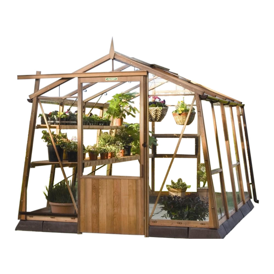
- Page 1 8’ Wide AMATEUR CEDAR GREENHOUSE ASSEMBLY INSTRUCTIONS PLEASE READ ALL INSTRUCTIONS BEFORE PROCEEDING 10/10...
-
Page 2: Table Of Contents
Fixing End Gable and First Side Panel SHELVING AND STAGING Fixing the Plain Gable End High Level Shelving 26-27 Fixing the remaining Side Panels Staging Assembly Fixing Door End Gable Glass details 29-30 ALTON GREENHOUSES, Station Works, Fenny Compton, Southam, Warwickshire CV47 2XB Telephone: 01295 770795... -
Page 3: Your New Greenhouse
YOUR NEW CEDAR GREENHOUSE Introduction Planning and preparation Thank you for buying an Alton Cedar Greenhouse. All of the illustrations relate to a 10’6”/3.20m long Please read carefully through these instructions Amateur Greenhouse. For other models you will before beginning to put your greenhouse up. - Page 4 OPTIONAL ACCESSORIES Get even more out of greenhouse Cladding Alton have a range of accessories which will add Alton Cladding is an ‘instant fit’ cedar wood extra benefits to your new Amateur greenhouse. cladding which simply clips over the outside of the greenhouse.
-
Page 5: Siting Your Greenhouse
Finally, and most importantly choose a site where your Alton Greenhouse will look right so that it will complement to your garden. page 5... -
Page 6: Concrete Base Kerbs
CONCRETE BASE KERBS Base kerb dimensions INTERNAL DIMENSIONS EXTERNAL DIMENSIONS Model Width Length Diagonal Width Length Diagonal 8’0” x 5’6” 7’5” (2261mm) 4’9” (1448mm) 8’ 9 ” (2685mm) 8’3” (2515mm) 5’3 ” (1619mm) 9’9 ” (2991mm) 8’0” x 8’0” 7’5” (2261mm) 7’3 ”... -
Page 7: Fixing To Concrete Kerbs
FIXING TO CONCRETE KERBS Fixing of cills to concrete kerbs Fixing end Gable and the first side panel Layout the wooden cills in position making sure fig 3 the side cills bevelled edge faces outwards from fig 2 the building. There is no bevel on the gable end cills. - Page 8 FIXING GABLE END & SIDES Fixing plain gable end and side panels Fix the sections together with 3 off 3 ” (85mm) The lift up vents will require the transit blocks to bolts, washers and nuts as shown in fig 5. It’s a be removed to give access to all the fixing holes.
-
Page 9: Fixing The Remaining Side Panels
FIXING SIDE PANELS Fixing the remaining side panels fig 8 fig 6 fig 7 fig 5 fig 9 fig 8 Repeat the same procedures for fitting the Fix the plastic tongue in the slot between the side remaining side sections in place. Where side panels. - Page 10 FIXING DOOR END GABLE Fixing Door End Gable fig 1 Fix door gable end to the cills with 2” / 50mm countersunk screws through each pre-drilled hole. If the side vent is next to the door gable the bolts must be reversed as shown in fig 3. Use 3 off ”/70mm bolts, washers and nuts plus the plastic covers.
- Page 11 PARTITION OPTIONAL Partition assembly It is important that the partition assembly is fig 1 see fig 4 see fig 2 completed at this stage - before the remaining end panels and roof panels are fixed. Gather all parts required for the partition assembly.
- Page 12 PARTITION OPTIONAL Partition assembly DO NOT fix a plate any lower than 333mm from the eaves as this will impair the ventaccess fig 5 operation. NOTE 2: Be sure that the bracket which secures the partition to the roof sections will NOT interfere with the high level shelving fixtures.
- Page 13 RIDGE BAR Preparation and Fixing of Ridge Bar On models over 13’/3.96m the ridge may be fig 1 supplied in sections. Lay them upside down on fig 2 & level ground and join them by overlapping the cut ends and securing them with the metal channel which is fixed with 4 off 1 ”/32mm countersunk screws.
- Page 14 RIDGE BAR / ROOF PANELS Preparation and Fixing of Ridge Bar Fixing Roof Panels Apply the sealing mastic to the ridge, either when Prior to commencing the assembly of the roof its fixed in position or now while it’s still on the gather together all the necessary bolts, washers, ground.
- Page 15 ROOF PANELS Fixing Roof Panels Now repeat the above with the roof panel on the fig 3 opposite side of the greenhouse. When they are both in place with all bolts and screws fitted you can tighten the screws holding the ridge bracket to the ridge.
- Page 16 ROOF PANELS Fixing roof Vents and Caps If you have roof vents adjacent (either side) to fig 8 each other you will have to trim the vent caps as detailed in fig 7. Note: if you have more than one set of adjacent roof vents, these will require cutting at both ends fig 7...
- Page 17 ROOF FASCIAS & FINIALS Fixing the Roof Fascias and Finials The gable roof cover strips (4) should be fitted fig 2 next. At the door end you will need to cut out the necessary gap for the door post. fig 1 fig 4 fig 2 fig 3...
- Page 18 BRACING & SUPPORTS DIFFERENT BRACING AND SUPPORT METHODS ARE REQUIRE FOR DIFFERENT LENGTHS OF GREENHOUSE, PLEASE READ CAREFULLY BEFORE PROCEEDING Bracing and Supports fig 2 fig 3 Gable end fig 3 fig 4 braces are fixed as shown in fig 4 & 5. Double check the verticals before...
- Page 19 BRACING THE GREENHOUSE Bracing the Greenhouse on models exceeding 13’ / 3.96m On all models 15’ 7”/ 4.75mm a MIDDLE fig 2 fig 1 BRACE is fitted instead of a standard brace at every roof/side section join. See fig 1. Standard eave braces are fitted (on all models) to all other glazing bars except at the gable ends.
- Page 20 SINGLE DOOR Fixing the Single Door see fig 2 see fig 3/4 fig 2 fig 1 To help you get the correct clearance under the door it can help to lay the timber door stop (slamming strip) on level ground at the door entrance so the under side is level with the fig 3 bottom of the kerbs.
- Page 21 SINGLE DOOR Fixing Single Doors · Handle + Staple fig 5 fig 8 see fig 8 see fig 9 886mm see fig 7 Positioning of the metal bottom door guide is important. The door must not rest on the guide, it must hang by the rollers in the top track and have a clearance between the door and the bottom Staple...
- Page 22 DOOR HANDLE Fixing the door handle To fix the new handle, decide on your preferred position and hold the handle to the frame while you drill two 5mm screw holes into the door frame. Where the drill has marked the inside of the handle drill two small pilot holes.
- Page 23 LOUVRE VENTS OPTIONAL Louvre Vent Assembly and Fitting Louvre vents are fitted at staging height and are position, pushing fig 2 positioned to complement other ventilation gently upwards to available: eg ventaccess and roof vents. ensure a good fit 21” / 535mm They can only be fitted where the glass you and make secure are replacing is 730 x 1422mm.
- Page 24 VENTILATION Ventilator Options fig 1 see fig 2 3 & 4 fig 2 fig 5 fig 3 Offset Stud Central Stud If you have not ordered an Automatic Opener as an optional extra we supply a casement stay for each roof vent. With the roof vent closed fix the casement stay centrally to the roof vent with 2 off ”/ 19mm...
- Page 25 GUTTERING IF YOU HAVE A RAINWATER ADAPTOR KIT, PLEASE SEE SEPARATE INSTRUCTIONS SUPPLIED WITH THE KIT. Gutter Assembly and Fitting Tighten up the downpipe and fix the shoe at the Decide at which end the downpipes will be bottom. See fig 6. located.
- Page 26 HIGH LEVEL SHELVING High Level Shelving The high level shelving can be fitted on either side of the greenhouse. fig 3 There are two different brackets for supporting the shelving against the side of the greenhouse. Those in figure 2 are fitted at each end of the greenhouse or at the end of the shelving when against a fig 1 fig 2...
- Page 27 HIGH LEVEL SHELVING High Level Shelving You may need to attached an additional bracket to Position narrow the end of this strap when fitting shelving next to a fig 6 side against " / 19mm partition post roundhead screw partition. See fig 6. You will need to modify shelving when fitting shelving in a building with middle brace.
- Page 28 STAGING Staging Assembly Fitting of 700mm staging on 8ft Amateur touching the string and fig 2 The staging can be fitted on either side of the fitted using the 40mm greenhouse. 3/4” roundhead screws screws. Where 2 pieces of staging join there will need to be 2 brackets fig 1 fixed.
- Page 29 8’ wide Amateur Cedar Greenhouse Glass Details In the event that any glass is broken upon delivery Door End Gable Glass we ask that you purchase the glass locally and forward us the bill for repayment. This will be the 554mm quickest way to rectify matters and get your greenhouse completed.
- Page 30 GLASS DETAILS Roof & Side glazing Partition glazing Roof Panel glass 730mm 730mm 318mm 1080mm 702mm Side Panel glass 730mm 730mm 518mm Side Panel 838mm 1422mm 1436mm 1422mm 584mm 718mm 586mm Door Panel 772mm Top Panels 141mm 317mm Glass details for left hand partition section. The right hand glass are exactly the same sizes.
- Page 31 page 31...
- Page 32 ALTON Greenhouses, Station Works, Fenny Compton, Southam, Warwickshire CV47 2XB Telephone: 01295 770795 · Fax: 01295 770819 10/10...
Need help?
Do you have a question about the Amateur 8’0” x 5’6” and is the answer not in the manual?
Questions and answers