Aruba Instant On 1930 Series Installation And Getting Started Manual
Hide thumbs
Also See for Instant On 1930 Series:

Related Manuals for Aruba Instant On 1930 Series


Summary of Contents for Aruba Instant On 1930 Series
- Page 1 Aruba Instant On 1930 Installation and Getting Started Guide Part Number: 5200-5878 Published: May 2020 Edition: 1...
- Page 2 © Copyright , 2020 Hewlett Packard Enterprise Development LP Notices The information contained herein is subject to change without notice. The only warranties for Hewlett Packard Enterprise products and services are set forth in the express warranty statements accompanying such products and services. Nothing herein should be construed as constituting an additional warranty. Hewlett Packard Enterprise shall not be liable for technical or editorial errors or omissions contained herein.
-
Page 3: Table Of Contents
Contents Chapter 1 About this document..............Applicable products............................5 Related publications............................5 Chapter 2 Overview.................... Switch hardware features..........................6 Network ports............................10 Power............................1930 switch series PoE power delivery................Ethernet Alliance PoE Certified.................... LEDs..............................Mode button............................Reset button............................Power connector..........................Switch features............................. Chapter 3 Site preparation and switch installation precautions..Safety recommendations.......................... - Page 4 Troubleshooting................... Testing the switch by resetting it........................ Restoring to Factory Defaults........................Chapter 7 Specifications..................44 Environmental specifications........................Acoustics................................45 Safety................................Standards..............................Cabling and Technology Information Specifications................46 Technology Distance Specifications....................Chapter 8 Support information..............Aruba Instant On 1930 Installation and Getting Started Guide...
-
Page 5: Chapter 1 About This Document
Aruba Instant On 1930 48G Class 4 PoE JL686A 4SFP/SFP+ 370W Switch Used with the JL680A Aruba Instant On 1930 8G 2SFP Switch. All other Aruba Instant On 1930 switches operate with internal power supplies. Related publications • Aruba Instant On 1930 Switch Series Quick Setup Guide and Safety/Regulatory Information •... -
Page 6: Chapter 2 Overview
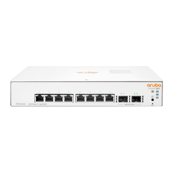
Overview The Aruba Instant On 1930 Switch series are designed to meet the needs of small business network environments - simple to setup and manage, secure and reliable. Aruba Instant On deployments can be managed through a Mobile App supported on iOS and Android, a cloud portal that is accessible through a web browser, or a local web GUI. - Page 7 Item Description Reset pushbutton (recessed) LED Mode pushbutton Figure 2: JL681A Item Description 1GbE RJ45 ports with Link/Status LED per port 1GbE SFP port with Link/Status LED Cloud Status LED Global Status LED UID LED PoE Mode LED Speed Mode LED Reset pushbutton (recessed) LED Mode pushbutton Figure 3: JL682A...
- Page 8 Description 1GbE RJ45 ports with Link/Status LED per port 10GbE SFP+ port with Link/Status LED Cloud Status LED Global Status LED UID LED PoE Mode LED Speed Mode LED Table Continued Aruba Instant On 1930 Installation and Getting Started Guide...
- Page 9 Item Description Reset pushbutton (recessed) LED Mode pushbutton Figure 5: JL684A Item Description 1GbE RJ45 ports with Link/Status LED per port 10GbE SFP+ port with Link/Status LED Cloud Status LED Global Status LED UID LED PoE Mode LED Speed Mode LED Reset pushbutton (recessed) LED Mode pushbutton Figure 6: JL685A...
-
Page 10: Network Ports
• Auto-sensing 10/100/1000BASE-T ports: These ports have the “Auto-MDIX” feature, which means that you can use either straight-through or crossover twisted-pair cables to connect any network devices to the switch. • Power-over-Ethernet (PoE) ports: Aruba Instant On 1930 Installation and Getting Started Guide... -
Page 11: Poe Power
• SFP slots for fiber or copper uplinks: Using Aruba SFPs, these products support optional network connectivity with the following speeds and technologies: NOTE: Transceivers not on the 1930 approved list are used at your own risk and may void support and warranty. -
Page 12: Ethernet Alliance Poe Certified
Maximum 30W delivered per PoE port. Ethernet Alliance PoE Certified ™ Certified Aruba PoE power sourcing equipment (PSE) has been verified for IEEE 802.3 PoE interoperability by passing the Ethernet Alliance (Gen 1 or Gen 2) PoE Certified program test plan, minimizing interoperability issues between PoE products. -
Page 13: Leds
For more information on EA PoE Certification, visit the Ethernet Alliance website. LEDs The front panel of the switch provides status LEDs for system monitoring. The following table details the functions of the various indicators. State Meaning Global Status On solid The switch has passed self-test and is powered up normally. - Page 14 On solid orange - PoE Mode is selected. A port has an internal PoE ◦ hardware failure. The specific port LED should flash simultaneously with Global Status LED. • Mode (Spd) not selected. • Mode (PoE) not selected. Table Continued Aruba Instant On 1930 Installation and Getting Started Guide...
-
Page 15: Mode Button
State Meaning Slow flash Locator LED identifying switch located. (blue) One of these condition exists: • User has not activated the Locator LED. • User has turned off the Locator LED. • User-configurable timeout period has expired; default time-out period is 30 minutes. -
Page 16: Power Connector
1930 switches do not have a power switch. They are powered on when connected to an active power source. Switches powered on when connected to an active AC power source • Aruba Instant On 1930 8G Class 4 PoE 2SFP 124W Switch (JL681A) • Aruba Instant On 1930 24G 4SFP/SFP+ Switch (JL682A) •... - Page 17 Web browser interface — an easy to use, built-in graphical interface that can be accessed from ◦ common Web browsers. Arubu Instant On Portal -- allows network administrators to configure and monitor Aruba Instant On ◦ switches and wireless access points through a mobile application or desktop browser app.
-
Page 18: Chapter 3 Site Preparation And Switch Installation Precautions
Before installing an Aruba Instant On 1930 switch, and to avoid possible bodily injury and equipment damage, carefully read these information sources before installation: • START HERE: Setup, Safety, and Regulatory Information for the Aruba Instant On 1930 Switch Series (shipped with the switch and also available online. - Page 19 • All Aruba Instant On 1930 Switches support table-top mounting. • All Aruba Instant On 1930 Switches except JL680A support rack-mounting. • All Aruba Instant On 1930 Switches support wall-mounting with ports facing either up or down. • All Aruba Instant On 1930 Switches support under-table mounting.
-
Page 20: Prepare The Installation Site
NOTE: The following Aruba Instant On 1930 switch models have a fan-free design, making them quiet for office deployments. • Aruba Instant On 1930 8G 2SFP Switch (JL680A) • Aruba Instant On 1930 8G PoE Class 4 2SFP 124WSwitch (JL681A) •... -
Page 21: Installation Space Requirements
• Under a table • On a horizontal surface Installation space requirements Switch Clearance Requirements Orientation Front At least 7.6 cm (3 inches) of space for the twisted-pair and fiber-optic cabling. Back At least 3.8 cm (1 1/2 inches) of space for the power cord and switch cooling. Sides At least 7.6 cm (3 inches) for cooling, except if the switch is installed in an open EIA/TIA rack. -
Page 22: Chapter 4 Installation Overview
This chapter shows how to install the switches. Fan-free design on some switch models The following Aruba Instant On 1930 switch models have a fan-free design, making them quiet for office deployments. -
Page 23: Installation Procedure
JL686A, JL685A, JL684A, JL683A, JL682A Kit number 5300-1029 four rubber feet ◦ two rack-mounting brackets ◦ screw kit (eight 8mm M4, four 12-24) ◦ JL681A switches Kit number 5300-1030 four rubber feet ◦ two 4.5 in. rack-mounting brackets ◦ screw kit (eight 8 mm M4; four 12-24) ◦... -
Page 24: Prepare The Installation Site
NOTE: Use only Aruba transceivers in 1930 switches. Using any other transceivers is done at your own risk and may void support and warranty. 1. Prepare the installation site If you have not already done so, carefully read Site preparation and switch installation precautions. Be sure to follow the provided guidelines to ensure proper operation when installing the switch into a network: 2. - Page 25 NOTE: The 1930 switches do not have a power switch. They are powered on when the power cord is connected to the switch and to a power source. For safety, locate the switch installation near the power outlet. The switches automatically adjust to any voltage between 100-127 or 200-240 volts and either 50 or 60 Hz.
- Page 26 If the ports are not connected to active network devices, the port Link/Act, Speed, and PoE status will be off. Refer to Diagnosing with the LEDs for diagnostic help. 3. Remove power to the switch before mounting. Aruba Instant On 1930 Installation and Getting Started Guide...
-
Page 27: Mount The Switch
◦ Rack or cabinet mounting All switches, except the Aruba Instant On 1930 8G 2SFP Switch (JL680A), can be mounted in a rack. The switches are designed to be mounted in any EIA-standard 19-inch Telco rack or communication equipment cabinet. -
Page 28: Wall Mounting
1. Use a #1 Phillips (cross-head) screwdriver and attach the mounting brackets to the switch with the included 8-mm M4 screws. 2. Attach the switch to the wall or wood surface with two 5/8-inch number 12 wood screws (not included). Aruba Instant On 1930 Installation and Getting Started Guide... - Page 29 To mount the 8-port switches, follow these steps: 1. In the required location, mark the position for the mounting screws. The hole-to-hole distance is 4.961 inch (126 mm) for JL680A and 6.575 inch (167 mm) for JL681A. 2. Use a #1 Phillips (cross-head) screwdriver and two of the included 20-mm M4 tap screws. Set the screw heads approximately 2 mm away from the mounting surface to allow the switch to slide onto the screws.
-
Page 30: Horizontal Surface Mounting
Use a sturdy surface in an uncluttered area. You may want to secure the networking cables and switch power cord to the table leg or other part of the surface structure to help prevent tripping over the cords. Aruba Instant On 1930 Installation and Getting Started Guide... -
Page 31: Connect The Switch To A Power Source
NOTE: Nothing should be placed on top of the switch. Adequate spacing on all sides needs to be maintained for ventilation. 4. Connect the switch to a power source Procedure 1. For JL680A switches, connect the AC/DC adapter’s power cord to the power connector on the back of the switch, and then plug the AC/DC power adapter into a nearby, properly grounded electrical outlet. - Page 32 The switches automatically adjust to any voltage between 100-127 or 200-240 volts and either 50 or 60 Hz. There are no voltage range settings required. 2. Use the included cable tie to secure the power cord to the switch. Aruba Instant On 1930 Installation and Getting Started Guide...
-
Page 33: Connect The Network Cables
5. Connect the network cables Connect the network cables, from the network devices or your patch panels, to the fixed RJ-45 ports on the switch or to any SFP transceivers you have installed in the switch. 100–ohm unshielded or shielded twisted pair cable: •... -
Page 34: Supported Transceivers
NOTE: Ensure the network cable is NOT connected when you install or remove an SFP. Supported Transceivers NOTE: Aruba 1930 switches do not support 100FX transceivers. NOTE: JL680A and JL681A switches support SFP (upto 1G) transceivers (2 per unit). JL682A, JL683A, JL684A, JL685A, JL686A all support SFP+ (up to 10G) (4 per unit). -
Page 35: Installing The Sfps
Remove the protective plastic cover and retain it for later use. Hold the SFP by its sides and gently insert it into any of the slots on the switch until the SFP clicks into place. WARNING: The Aruba SFPs are Class 1 laser devices. Avoid direct eye exposure to the beam coming from the transmit port. -
Page 36: Removing The Sfps
Use only an approved Laser Class 1 SFP transceiver. NOTE: To ensure proper operation of your switch, use only the Aruba SFP transceivers supported by your switch. -
Page 37: Chapter 5 Initial Configuration
URL. A landing page displays asking you to choose how to manage the switch. If you choose to proceed using the Aruba Instant On Cloud Portal, follow the instructions within the portal's interface. Otherwise, click Connect and follow the steps below. -
Page 38: Using The 192.168.1.1 Ip Address
8. Click Apply to implement the new password, and then click Save Configuration at the top of the browser configuration screen to save your settings and retain them when the switch is rebooted. See the Aruba Instant On 1930 Switch Series Management and Configuration Guide for more switch configuration information. -
Page 39: Where To Go From Here
For more information on the local web interface and all the features that can be configured on the 1930 Switch Series, see the Aruba Instant On 1930 Switch Series Management and Configuration Guide. For more information on using the Aruba Instant On Portal to manage the switch, see the Aruba Instant On User Guide. -
Page 40: Chapter 6 Troubleshooting
Troubleshooting Troubleshooting overview This section describes how to troubleshoot the switch. For more information, see Aruba Instant On 1930 8G/24G/48G Switch Series Management and Configuration Guide. This chapter describes the following: • basic troubleshooting tips – Basic troubleshooting tips • diagnosing with the LEDs – Diagnosing with the LEDs •... -
Page 41: Diagnostic Tips
If the power source and power cord are OK and this condition persists, the switch power supply may have failed. Call your Aruba authorized network reseller, or use the electronic support services from Aruba to get assistance. A switch hardware Try power cycling the switch. -
Page 42: Led Patterns For Poe Troubleshooting
Link LED is port may have failed. To confirm, try a different port that appears to be blinking has good. Call your Aruba authorized network reseller, or use the electronic experienced a self test support services from Aruba to get assistance. -
Page 43: Testing The Switch By Resetting It
Problem Solution PoE oversubscription If possible add additional PoE power, or redefine port priorities. ➊ condition. All available PoE power is already taken by higher-priority ports. PoE hardware fault. A The switch must be replaced. ➋ switch hardware component that is involved with PoE power delivery has failed. -
Page 44: Chapter 7 Specifications
6.28" x 10" x 1.73" 2.55 lb (JL680A) (15.95 x 25.4 x 4.39 cm) (1.16 kg) Aruba Instant On 1930 8G PoE Class 4 2SFP 10" x 10" x 1.73" 4.66 lb 124W Switch (JL681A) (25.4 x 25.4 x 4.39 cm) (2.11 kg) -
Page 45: Acoustics
Acoustics Noise Emmission Aruba Instant On 1930 8G 2SFP Switch (JL680A) Power: 0 dB no fan Aruba Instant On 1930 8G PoE Class 4 2SFP 124W Power: 0 dB no fan Switch (JL681A) Aruba Instant On 1930 24G 4SFP/SFP+ Switch... -
Page 46: Cabling And Technology Information Specifications
When testing your cabling, be sure to include the patch cables that connect the switch and other end devices to the patch panels on your site. The patch cables are frequently overlooked when testing cable and they must also comply with the cabling standards. Aruba Instant On 1930 Installation and Getting Started Guide... -
Page 47: Technology Distance Specifications
Technology Distance Specifications Technology Supported cable type Multimode fibermodal Supported distances bandwidth 1000-T twisted-pair copper up to 100 meters 1000-SX multimode fiber 160 MHz*km 2 - 220 meters 200 MHz*km 2 - 275 meters 400 MHz*km 2 - 500 meters 500 MHz*km 2 - 550 meters 1000-LX... -
Page 48: Chapter 8 Support Information
Support information Main Instant On site https://www.arubainstanton.com/ Support https://support.arubainstanton.com/ Instant On social forums and knowledge base https://community.arubainstanton.com/ Security bulletins https://www.arubanetworks.com/support-services/security-bulletins/ End-user license agreement https://www.arubainstanton.com/eula/ Support contact numbers https://www.arubainstanton.com/contact-support/ Aruba Instant On 1930 Installation and Getting Started Guide...
Need help?
Do you have a question about the Instant On 1930 Series and is the answer not in the manual?
Questions and answers